EP0150679B1 - Rahmbläserkopf - Google Patents
Rahmbläserkopf Download PDFInfo
- Publication number
- EP0150679B1 EP0150679B1 EP84810650A EP84810650A EP0150679B1 EP 0150679 B1 EP0150679 B1 EP 0150679B1 EP 84810650 A EP84810650 A EP 84810650A EP 84810650 A EP84810650 A EP 84810650A EP 0150679 B1 EP0150679 B1 EP 0150679B1
- Authority
- EP
- European Patent Office
- Prior art keywords
- cream
- aerated
- valve member
- housing
- movable valve
- Prior art date
- Legal status (The legal status is an assumption and is not a legal conclusion. Google has not performed a legal analysis and makes no representation as to the accuracy of the status listed.)
- Expired
Links
Images

Classifications
-
- B—PERFORMING OPERATIONS; TRANSPORTING
- B65—CONVEYING; PACKING; STORING; HANDLING THIN OR FILAMENTARY MATERIAL
- B65D—CONTAINERS FOR STORAGE OR TRANSPORT OF ARTICLES OR MATERIALS, e.g. BAGS, BARRELS, BOTTLES, BOXES, CANS, CARTONS, CRATES, DRUMS, JARS, TANKS, HOPPERS, FORWARDING CONTAINERS; ACCESSORIES, CLOSURES, OR FITTINGS THEREFOR; PACKAGING ELEMENTS; PACKAGES
- B65D83/00—Containers or packages with special means for dispensing contents
- B65D83/14—Containers for dispensing liquid or semi-liquid contents by internal gaseous pressure, i.e. aerosol containers comprising propellant
- B65D83/44—Valves specially adapted for the discharge of contents; Regulating devices
- B65D83/46—Tilt valves
-
- B—PERFORMING OPERATIONS; TRANSPORTING
- B65—CONVEYING; PACKING; STORING; HANDLING THIN OR FILAMENTARY MATERIAL
- B65D—CONTAINERS FOR STORAGE OR TRANSPORT OF ARTICLES OR MATERIALS, e.g. BAGS, BARRELS, BOTTLES, BOXES, CANS, CARTONS, CRATES, DRUMS, JARS, TANKS, HOPPERS, FORWARDING CONTAINERS; ACCESSORIES, CLOSURES, OR FITTINGS THEREFOR; PACKAGING ELEMENTS; PACKAGES
- B65D83/00—Containers or packages with special means for dispensing contents
- B65D83/14—Containers for dispensing liquid or semi-liquid contents by internal gaseous pressure, i.e. aerosol containers comprising propellant
- B65D83/16—Actuating means
- B65D83/164—Actuators comprising a manually operated valve and being attachable to the aerosol container, e.g. downstream a valve fitted to the container; Actuators associated to container valves with valve seats located outside the aerosol container
-
- B—PERFORMING OPERATIONS; TRANSPORTING
- B65—CONVEYING; PACKING; STORING; HANDLING THIN OR FILAMENTARY MATERIAL
- B65D—CONTAINERS FOR STORAGE OR TRANSPORT OF ARTICLES OR MATERIALS, e.g. BAGS, BARRELS, BOTTLES, BOXES, CANS, CARTONS, CRATES, DRUMS, JARS, TANKS, HOPPERS, FORWARDING CONTAINERS; ACCESSORIES, CLOSURES, OR FITTINGS THEREFOR; PACKAGING ELEMENTS; PACKAGES
- B65D83/00—Containers or packages with special means for dispensing contents
- B65D83/14—Containers for dispensing liquid or semi-liquid contents by internal gaseous pressure, i.e. aerosol containers comprising propellant
- B65D83/16—Actuating means
- B65D83/20—Actuator caps
- B65D83/206—Actuator caps comprising cantilevered actuating elements, e.g. levers pivoting about living hinges
-
- B—PERFORMING OPERATIONS; TRANSPORTING
- B65—CONVEYING; PACKING; STORING; HANDLING THIN OR FILAMENTARY MATERIAL
- B65D—CONTAINERS FOR STORAGE OR TRANSPORT OF ARTICLES OR MATERIALS, e.g. BAGS, BARRELS, BOTTLES, BOXES, CANS, CARTONS, CRATES, DRUMS, JARS, TANKS, HOPPERS, FORWARDING CONTAINERS; ACCESSORIES, CLOSURES, OR FITTINGS THEREFOR; PACKAGING ELEMENTS; PACKAGES
- B65D83/00—Containers or packages with special means for dispensing contents
- B65D83/14—Containers for dispensing liquid or semi-liquid contents by internal gaseous pressure, i.e. aerosol containers comprising propellant
- B65D83/42—Filling or charging means
Definitions
- the invention relates to a cream blower head according to the preamble of claim 1.
- CH-A-480 829 a bottle-shaped cream blower is described in which the bottom of the bottle is equipped with the means having a valve with which propellant gas can be admitted from a cartridge.
- the applicant has also brought cream blowers onto the market in which these agents are accommodated on the side in the cream blower head.
- these separate propellant gas inlet means represent a construction effort that has a significant share in the total manufacturing costs for the cream blower.
- the invention has for its object to design the cream blower head so that this effort is significantly reduced and thereby the manufacturing costs are significantly reduced, without affecting the ease of use.
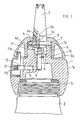
- FIG. 1 and 2 are two longitudinal sections of an exemplary embodiment which are similar to one another, with FIG. 1 showing the cream blower head screwed onto a cream blower bottle in the ready-to-use idle state, whereas FIG. 2 shows the state with the propellant gas cartridge fitted.
- the cream blower head shown has a housing which has a body 1 which is rotationally symmetrical about a longitudinal axis. This has an internal thread 1a a at one end to enable it to be screwed onto a cream bottle 2. At the other end, this housing body 1 has a projecting collar 1b onto which a housing cap 3 is screwed. This serves to hold a fixed valve body 4 in the center, which has a flat valve seat surface 4a on its side facing the bottle 2, whereas on the other side there is a neck-shaped extension 4b which is provided on the inside with a toroidal recess. A suitably designed end projection 5 a, which is provided on a mouthpiece 5, engages in this with a snap lock.
- a movable cream outlet valve member 6 cooperates with the valve body 4, more precisely, the plate-shaped part 7, on which an outwardly projecting pin-shaped projection 7a is also attached.
- the movable valve member 6 also includes an inwardly projecting rod-shaped extension 8 screwed into a threaded blind hole of the part 7.
- the valve is completed by a valve spring (compression spring) 9, which is effective between the part 7 and a shoulder of the housing body 1 to keep the valve in the closed position.
- an actuating element consisting of a spindle 10, which can be moved longitudinally in a sealed manner in a radial bore 1 of the housing body 1, and of an actuating button 11, which is press-fitted onto a knurled end part of the spindle 10 is.
- the actuating spindle 10 lies with its inner end on the rod-shaped extension 8 (or almost) and there is also a lateral projection 11 a of the button 11 on the inside of the lower edge of the housing cap 3.
- the user wants to skip the blown cream, he obviously only needs to press the button 11 so that the spindle 10 then acts on the lower end of the rod-shaped extension 8 and tilts it together with the valve part 7 in order to lift the latter off the seat 6; the blown cream can then pass through a lateral recess 1d of the housing body 1 along the rod-shaped extension 8, then around the part 7 into the bore of the fixed valve body 4 and then through the mouthpiece 5.
- the bore just mentioned in the valve body 4 has a diameter which (FIG. 2) corresponds to the plug-in part 12 of a commercially available gas cartridge 13.
- the pin-shaped projection 7a of the part 7 is long enough to push back the movable valve part 14, which is present in this plug-in part, when the plug-in part 12 is fully inserted, as soon as the part 7 itself has been moved back until it rests on an annular shoulder 1f of the housing body 1 to block the outlet of the propellant gas contained in the cartridge 13. This pushing back naturally raises this valve part from its seat and thus enables the propellant gas to get into the cream bottle 2 along the pin-shaped projection 7a and around the plate-shaped part 7 and finally through the recess 1d.
- valve 4, 6, 7 is not only an outlet valve for blown cream but also a ventilator-owned valve for retaining the propellant gas and actuating means for the admission of propellant gas from the gas cartridge into the creamer. This eliminates the need for any other propellant gas inlet means previously installed in the housing of the cream blower head, which cooperate with the propellant gas cartridge. This of course reduces the manufacturing effort, including the price.
- the actuating button 11 has an outer surface 11 b, which, when the actuating element assumes its rest position (shown in FIG. 1), with the geometrically uniform, preferably spherical outer surface 1e of the housing body 1 and 3a of the housing cap 3 coincides; this protects each other against damage when putting it down and also gives the whole fan head a pleasing appearance.
Landscapes
- Chemical & Material Sciences (AREA)
- Dispersion Chemistry (AREA)
- Engineering & Computer Science (AREA)
- Mechanical Engineering (AREA)
- Containers And Packaging Bodies Having A Special Means To Remove Contents (AREA)
- Formation And Processing Of Food Products (AREA)
- Confectionery (AREA)
- Closures For Containers (AREA)
Description
- Die Erfindung betrifft einen Rahmbläserkopf nach dem Oberbegriff von Patentanspruch 1.
- In der CH-A- 480 829 ist ein flaschenförmiger Rahmbläser beschrieben, bei dem der Boden der Flasche mit den ein Ventil aufweisenden Mitteln ausgerüstet ist, mit denen aus einer Patrone Treibgas eingelassen werden kann.
- Die Anmelderin hat auch Rahmbläser auf den Markt gebracht, bei denen diese Mittel seitlich im Rahmbläserkopf untergebracht sind.
- Im einen wie im anderen Fall stellen diese gesonderten Treibgaseinlassmittel einen baulichen Aufwand dar, der einen wesentlichen Anteil an den gesamten Fertigungskosten für den Rahmbläser hat.
- Der Erfindung liegt die Aufgabe zugrunde, den Rahmbläserkopf so auszubilden, dass dieser Aufwand erheblich verringert ist und dadurch auch die Fertigungskosten erheblich vermindert sind, und zwar ohne Beeinträchtigung des Handhabungskomfortes.
- Die Lösung dieser Aufgabe wird primär in einer Ausbildung gesehen, wie sie im kennzeichnenden Teil des Anspruches 1 umschrieben ist. Inbezug auf weitere Besonderheiten einer bevorzugten Ausführungsform wird auf die abhängigen Ansprüche hingeweisen.
- Die Erfindung wird nachfolgend unter Bezugnahme auf die beiliegende Zeichnung beispielsweise erläutert.
- Die Fig. 1 und 2 sind zwei einander ähnliche Längsschnitte eines Ausführungsbeispieles, wobei die Fig. 1 den auf eine Rahmbläserflasche aufgeschraubten Rahmbläserkopf im gebrauchsbereiten Ruhezustand zeigt, wogegen Fig. 2 den Zustand bei aufgesetzter Treibgaspatrone zeigt.
- Der dargestellte Rahmbläserkopf hat ein Gehäuse, das einen um eine Längsachse rotationssymmetrischen Körper 1 aufweist. Dieser hat am einen Ende ein Innengewinde 1a a zur Ermöglichung seines Aufschraubens auf eine Rahmflasche 2. Am anderen Ende hat dieser Gehäusekörper 1 einen vorstehenden Kragen 1b, auf den eine Gehäusekappe 3 aufgeschraubt ist. Diese dient zum zentrierten Festhalten eines feststehenden Ventilkörpers 4, der eine flache Ventilsitzfläche 4a hat auf seiner der Flasche 2 zugewendeten Seite, wogegen an der anderen Seite ein halsförmiger Ansatz 4b vorhanden ist, der innenseitig mit einer toroidalen Ausdrehung versehen ist. In diese greift mit Schnappverschluss ein passend ausgebildeter Endansatz 5a ein, der an einem Mundstück 5 vorhanden ist. Mit dem Ventilkörper 4 arbeitet ein bewegliches Rahmauslassventilglied 6 zusammen, genauer gesagt, der tellerförmige Teil 7, an dem einstückig auch ein nach aussen ragender zapfenförmiger Vorsprung 7a angesetzt ist. Zum beweglichen Ventilglied 6 gehört auch ein in ein Gewindesackloch des Teiles 7 eingeschraubter, nach innen ragender stangenförmiger Ansatz 8. Das Ventil wird vervollständigt durch eine Ventilfeder (Druckfeder) 9, die zwischen dem Teil 7 und einer Schulter des Gehäusekörpers 1 wirksam ist, im Bestreben, das Ventil in Schliesslage zu halten. Zum Öffnen dieses Ventiles, also zum Abgeben von geblasenem Rahm dient ein Betätigungsglied, bestehend aus einer Spindel 10, die abgedichtet in einer Radialbohrung 1 des Gehäusekörpers 1 längsverschiebbar ist, und aus einem Betätigungsknopf 11, der mit Preßsitz auf einen gerändelten Endteil der Spindel 10 aufgepresst ist. In der gezeigten Ruhelage liegt die Betätigungsspindel 10 mit ihrem inneren Ende am stangenförmigen Ansatz 8 an (oder beinahe) und liegt ausserdem ein seitlicher Vorsprung 11 a des Knopfes 11 an der Innenseite des unteren Randes der Gehäusekappe 3 an. Wenn der Benützer geblasenen Rahm auslassen will, so braucht er offensichtlich nur auf den Knopf 11 zu drücken, damit die Spindel 10 dann auf das untere Ende des stangenförmigen Ansatzes 8 wirkt und diesen samt dem Ventilteil 7 kippt, um letzteren von der Sitzfläche 6 abzuheben; der geblasene Rahm kann dann durch eine seitliche Aussparung 1d des Gehäusekörpers 1 entlang dem stangenförmigen Ansatz 8, dann um den Teil 7 herum in die Bohrung des feststehenden Ventilkörpers 4 und anschliessend durch das Mundstück 5 hindurch nach aussen gelangen.
- Die eben erwähnte Bohrung im Ventilkörper 4 hat einen Durchmesser, der (Fig. 2) dem Einsteckteil 12 einer handelsüblichen Gaspatrone 13 entspricht. Der zapfenförmige Vorsprung 7a des Teiles 7 ist genügend lang, um beim vollständigen Einstecken des Einsteckteiles 12, sobald der Teil 7 selbst bis zum Aufliegen auf einer Ringschulter 1f des Gehäusekörpers 1 zurückbewegt worden ist, das bewegliche Ventilteil 14 zurückzudrängen, das in diesem Einsteckteil vorhanden ist zwecks Versperrens des Auslasses des in der Patrone 13 enthaltenen Treibgases. Durch dieses Zurückdrängen wird naturlich dieses Ventilteil von seinem Sitz abgehoben und es wird somit dem Treibgas ermöglicht, am zapfenförmigen Vorsprung 7a entlang und um den tellerförmigen Teil 7 herum und schliesslich auch durch die Aussparung 1d hindurch in die Rahmflasche 2 hineinzugelangen.
- Dank dieser zuletzt beschriebenen Ausbildung des Ventiles 4, 6, 7 ist dieses nicht nur Auslassventil für geblasenen Rahm sondern auch rahmbläsereigenes Ventil für das Zurückhalten des Treibgases und Betätigungsmittel für den Einlass von Treibgas aus der Gaspatrone in den Rahmbläser hinein. Somit erübrigen sich jegliche sonstigen, bisher im Gehäuse des Rahmbläserkopfes eingebaute Treibgaseinlassmittel, die mit der Treibgaspatrone zusammenarbeiten. Dadurch wird natürlich der Fertigungsaufwand, also auch der Preis, vermindert.
- Wie aus der Zeichnung ersichtlich ist, hat der Betätigungsknopf 11 eine Aussenfläche 11 b, die, wenn das Betätigungsorgan seine (in Fig. 1 gezeigte) Ruhelage einnimmt, mit der geometrisch einheitlichen, vorzugsweise kugeligen Aussenfläche 1e des Gehäusekörpers 1 und 3a der Gehäusekappe 3 zusammenfällt; dadurch schützen sich diese Flächen gegenseitig gegen Beschädigung beim Ablegen und erhält ausserdem der ganze Gebläsekopf ein gefälliges Aussehen.
Claims (3)
Priority Applications (1)
| Application Number | Priority Date | Filing Date | Title |
|---|---|---|---|
| AT84810650T ATE26431T1 (de) | 1984-01-12 | 1984-12-20 | Rahmblaeserkopf. |
Applications Claiming Priority (2)
| Application Number | Priority Date | Filing Date | Title |
|---|---|---|---|
| CH152/84 | 1984-01-12 | ||
| CH152/84A CH662098A5 (de) | 1984-01-12 | 1984-01-12 | Rahmblaeserkopf. |
Publications (3)
| Publication Number | Publication Date |
|---|---|
| EP0150679A2 EP0150679A2 (de) | 1985-08-07 |
| EP0150679A3 EP0150679A3 (en) | 1985-09-11 |
| EP0150679B1 true EP0150679B1 (de) | 1987-04-08 |
Family
ID=4180432
Family Applications (1)
| Application Number | Title | Priority Date | Filing Date |
|---|---|---|---|
| EP84810650A Expired EP0150679B1 (de) | 1984-01-12 | 1984-12-20 | Rahmbläserkopf |
Country Status (4)
| Country | Link |
|---|---|
| EP (1) | EP0150679B1 (de) |
| AT (1) | ATE26431T1 (de) |
| CH (1) | CH662098A5 (de) |
| DE (1) | DE3463027D1 (de) |
Cited By (1)
| Publication number | Priority date | Publication date | Assignee | Title |
|---|---|---|---|---|
| EP0867219A1 (de) * | 1997-03-26 | 1998-09-30 | Kisag AG | Vorrichtung zum Karbonisieren einer Flüssigkeit |
Families Citing this family (1)
| Publication number | Priority date | Publication date | Assignee | Title |
|---|---|---|---|---|
| NL1003521C2 (nl) * | 1996-07-05 | 1998-01-12 | Menken Dairy Food B V | Bedieningssamenstel, een voor genoemd bedieningssamenstel bestemd mantelonderdeel en een spuitbus met een dergelijk bedieningssamenstel. |
Family Cites Families (6)
| Publication number | Priority date | Publication date | Assignee | Title |
|---|---|---|---|---|
| FR1249270A (fr) * | 1959-10-31 | 1960-12-30 | Dispositif de commande pour soupape à clapet-pilote et ses applications | |
| GB946006A (en) * | 1960-12-22 | 1964-01-08 | Risdon Mfg Co | Improvements in dispensing devices for pressurised liquid containers |
| CH354049A (de) * | 1962-03-30 | 1961-06-30 | Fritz Mueller | Gerät zur Herstellung von Schlagrahm, Mayonnaise sowie Schokolade- und Vanillecreme, mittels Druckgas |
| CH480829A (de) * | 1967-02-17 | 1969-11-15 | Kisag Ag | Flaschenförmiger Rahmbläser |
| CA927333A (en) * | 1970-04-09 | 1973-05-29 | The Gillette Company | Aerosol valve assembly |
| CH639258A5 (en) * | 1979-01-15 | 1983-11-15 | Kisag Ag | Device for dispensing water or cream mixed with gas |
-
1984
- 1984-01-12 CH CH152/84A patent/CH662098A5/de not_active IP Right Cessation
- 1984-12-20 EP EP84810650A patent/EP0150679B1/de not_active Expired
- 1984-12-20 AT AT84810650T patent/ATE26431T1/de not_active IP Right Cessation
- 1984-12-20 DE DE8484810650T patent/DE3463027D1/de not_active Expired
Cited By (1)
| Publication number | Priority date | Publication date | Assignee | Title |
|---|---|---|---|---|
| EP0867219A1 (de) * | 1997-03-26 | 1998-09-30 | Kisag AG | Vorrichtung zum Karbonisieren einer Flüssigkeit |
Also Published As
| Publication number | Publication date |
|---|---|
| EP0150679A2 (de) | 1985-08-07 |
| CH662098A5 (de) | 1987-09-15 |
| ATE26431T1 (de) | 1987-04-15 |
| EP0150679A3 (en) | 1985-09-11 |
| DE3463027D1 (en) | 1987-05-14 |
Similar Documents
| Publication | Publication Date | Title |
|---|---|---|
| DE69011562T2 (de) | Pumpe zur Abgabe einer in einem Behälter enthaltenen Flüssigkeit. | |
| DE1482675C3 (de) | Sprühvorrichtung | |
| EP0167863B1 (de) | Variabel ventilierbare Filterzigarette | |
| DE1425896A1 (de) | Kappe fuer Aerosolbehaelter | |
| DE2264055B2 (de) | Ventil fuer gasfeuerzeug | |
| DE60006301T2 (de) | Ausgabekopf zur Ausgabe eines unter Druck stehenden Stoffs sowie eine mit einem solchen Ausgabekopf versehene Ausgabevorrichtung | |
| AT241179B (de) | Gasfeuerzeug | |
| DE1625235A1 (de) | Spruehduesenvorrichtung | |
| CH662098A5 (de) | Rahmblaeserkopf. | |
| US665608A (en) | Comb. | |
| EP1118554A1 (de) | Sprühkappe mit integriertem Sprühkopf | |
| DE1400735A1 (de) | Nachfuellbare Spruehdose | |
| DE2359855C3 (de) | Zerstäubungsvorrichtung für einen Aerosolbehälter | |
| DE3032184A1 (de) | Benzinkanister | |
| DE1598042B2 (de) | Pipettenverschluß zur gleichzeitigen Abgabe und Verteilung von Flüssigkeiten | |
| DE2057657C3 (de) | Feuerzeug mit auswechselbarer Zündvorrichtung | |
| US2234772A (en) | Dispensing container | |
| DE2921204C2 (de) | Vorratsflasche zur dosierten Abgabe einer Teilmenge der eingefüllten Flüssigkeit | |
| DE1209968B (de) | Spruehkopf fuer elastische Kunststoffflaschen mit Spruehduese, Lufteinlassventil und einer die Duesenoeffnung und die Lufteinlassoeffnung abschliessenden Kappe | |
| AT220010B (de) | Ausgußvorrichtung für Behälter | |
| DE1575040C3 (de) | Betätigungsvorrichtung als Zubehör für eine unter Druck stehende Sprühdose | |
| DE1775477C3 (de) | Zerstäuberkopf | |
| DE8715396U1 (de) | Auf dem Hals von Tuben, Flaschen o.dgl. anzuordnende Verschlußkappe | |
| DE1425869C (de) | Spruhventil eines Aerosol Zerstäubers | |
| DE1930089C (de) | Kappe für eine Sprühdose |
Legal Events
| Date | Code | Title | Description |
|---|---|---|---|
| PUAI | Public reference made under article 153(3) epc to a published international application that has entered the european phase |
Free format text: ORIGINAL CODE: 0009012 |
|
| PUAL | Search report despatched |
Free format text: ORIGINAL CODE: 0009013 |
|
| AK | Designated contracting states |
Designated state(s): AT DE FR GB IT SE |
|
| AK | Designated contracting states |
Designated state(s): AT DE FR GB IT SE |
|
| 17P | Request for examination filed |
Effective date: 19850905 |
|
| 17Q | First examination report despatched |
Effective date: 19860613 |
|
| GRAA | (expected) grant |
Free format text: ORIGINAL CODE: 0009210 |
|
| AK | Designated contracting states |
Kind code of ref document: B1 Designated state(s): AT DE FR GB IT SE |
|
| REF | Corresponds to: |
Ref document number: 26431 Country of ref document: AT Date of ref document: 19870415 Kind code of ref document: T |
|
| REF | Corresponds to: |
Ref document number: 3463027 Country of ref document: DE Date of ref document: 19870514 |
|
| ITF | It: translation for a ep patent filed | ||
| ET | Fr: translation filed | ||
| PLBE | No opposition filed within time limit |
Free format text: ORIGINAL CODE: 0009261 |
|
| STAA | Information on the status of an ep patent application or granted ep patent |
Free format text: STATUS: NO OPPOSITION FILED WITHIN TIME LIMIT |
|
| 26N | No opposition filed | ||
| ITTA | It: last paid annual fee | ||
| EAL | Se: european patent in force in sweden |
Ref document number: 84810650.6 |
|
| PGFP | Annual fee paid to national office [announced via postgrant information from national office to epo] |
Ref country code: SE Payment date: 19951109 Year of fee payment: 12 |
|
| PGFP | Annual fee paid to national office [announced via postgrant information from national office to epo] |
Ref country code: FR Payment date: 19951110 Year of fee payment: 12 |
|
| PGFP | Annual fee paid to national office [announced via postgrant information from national office to epo] |
Ref country code: GB Payment date: 19951121 Year of fee payment: 12 |
|
| PGFP | Annual fee paid to national office [announced via postgrant information from national office to epo] |
Ref country code: DE Payment date: 19951122 Year of fee payment: 12 |
|
| PGFP | Annual fee paid to national office [announced via postgrant information from national office to epo] |
Ref country code: AT Payment date: 19951231 Year of fee payment: 12 |
|
| PG25 | Lapsed in a contracting state [announced via postgrant information from national office to epo] |
Ref country code: GB Effective date: 19961220 Ref country code: AT Effective date: 19961220 |
|
| PG25 | Lapsed in a contracting state [announced via postgrant information from national office to epo] |
Ref country code: SE Effective date: 19961221 |
|
| GBPC | Gb: european patent ceased through non-payment of renewal fee |
Effective date: 19961220 |
|
| PG25 | Lapsed in a contracting state [announced via postgrant information from national office to epo] |
Ref country code: FR Effective date: 19970829 |
|
| PG25 | Lapsed in a contracting state [announced via postgrant information from national office to epo] |
Ref country code: DE Effective date: 19970902 |
|
| EUG | Se: european patent has lapsed |
Ref document number: 84810650.6 |
|
| REG | Reference to a national code |
Ref country code: FR Ref legal event code: ST |