EP0150859A2 - Verfahren und Vorrichtung zur Herstellung von Fliesen, Platten und ähnlichen Konstruktionsblöcken durch Pressen einer Pulvermischung - Google Patents
Verfahren und Vorrichtung zur Herstellung von Fliesen, Platten und ähnlichen Konstruktionsblöcken durch Pressen einer Pulvermischung Download PDFInfo
- Publication number
- EP0150859A2 EP0150859A2 EP85101036A EP85101036A EP0150859A2 EP 0150859 A2 EP0150859 A2 EP 0150859A2 EP 85101036 A EP85101036 A EP 85101036A EP 85101036 A EP85101036 A EP 85101036A EP 0150859 A2 EP0150859 A2 EP 0150859A2
- Authority
- EP
- European Patent Office
- Prior art keywords
- pressing
- plates
- pressing cavity
- cavity
- movable
- Prior art date
- Legal status (The legal status is an assumption and is not a legal conclusion. Google has not performed a legal analysis and makes no representation as to the accuracy of the status listed.)
- Withdrawn
Links
Images
Classifications
-
- B—PERFORMING OPERATIONS; TRANSPORTING
- B28—WORKING CEMENT, CLAY, OR STONE
- B28B—SHAPING CLAY OR OTHER CERAMIC COMPOSITIONS; SHAPING SLAG; SHAPING MIXTURES CONTAINING CEMENTITIOUS MATERIAL, e.g. PLASTER
- B28B7/00—Moulds; Cores; Mandrels
- B28B7/16—Moulds for making shaped articles with cavities or holes open to the surface, e.g. with blind holes
- B28B7/164—Moulds for making shaped articles with cavities or holes open to the surface, e.g. with blind holes for plates, panels, or similar sheet- or disc-shaped articles
-
- B—PERFORMING OPERATIONS; TRANSPORTING
- B28—WORKING CEMENT, CLAY, OR STONE
- B28B—SHAPING CLAY OR OTHER CERAMIC COMPOSITIONS; SHAPING SLAG; SHAPING MIXTURES CONTAINING CEMENTITIOUS MATERIAL, e.g. PLASTER
- B28B3/00—Producing shaped articles from the material by using presses; Presses specially adapted therefor
- B28B3/02—Producing shaped articles from the material by using presses; Presses specially adapted therefor wherein a ram exerts pressure on the material in a moulding space; Ram heads of special form
-
- B—PERFORMING OPERATIONS; TRANSPORTING
- B28—WORKING CEMENT, CLAY, OR STONE
- B28B—SHAPING CLAY OR OTHER CERAMIC COMPOSITIONS; SHAPING SLAG; SHAPING MIXTURES CONTAINING CEMENTITIOUS MATERIAL, e.g. PLASTER
- B28B7/00—Moulds; Cores; Mandrels
- B28B7/10—Moulds with means incorporated therein, or carried thereby, for ejecting or detaching the moulded article
Definitions
- the present invention relates to the manufacture of tiles, panels and similar flat building elements, square or rectangular, by pressing a fluid mixture of low humidity powder in a pressing cavity defined by two opposite plates forming the faces of the tile and by four cheeks forming the edges of the tile.
- plaster tiles of the smooth facing type for example according to French standard NF-P-72301 are produced by pouring a liquid mass of plaster and mixing water into vertical molds. This manufacturing process, which requires drying the molded tiles, leads to tiles with a density of 0.9 to 1.
- the pressing is carried out between two horizontal plates movable vertically relative to one another.
- the dimensions (in horizontal projection) of the presses used are directly a function of the size of the tile to be manufactured.
- the height of these presses must also be significant since the filling of the pressing cavity requires a sufficient rise of the upper plate to allow the establishment of a filling system above the cavity.
- These presses are therefore very bulky and must be of very rigid structure.
- a second type of process consists in introducing the powder into a pressing cavity delimited by two fixed vertical plates spaced by a distance corresponding to the thickness of the tile to be produced and in pressing the powder between two opposite cheeks of the cavity defining two slices opposite of the tile.
- the pressing cavity is very narrow, the filling of the latter is problematic. The problem of regular filling is particularly serious in the case of a pressing cavity encumbered by cores, for the manufacture of hollow tiles.
- Another drawback common to the two types of process described above relates to the release of the tile from the pressing cavity. Indeed, according to these methods, this release is accompanied by tensile forces on the tile, causing tearing in particular on the edges, and more particularly at the grooves and tongues with which the tiles are generally provided on their edges, in view of their interlocking assembly.
- the subject of the present invention is a method and a device for manufacturing tiles, panels or similar flat building elements, by pressing a powder mixture, this method being able to be carried out in a simple manner on a compact press. and providing tiles with a regular density distribution, both on solid tiles and on hollow tiles.
- the subject of the invention is also a method and a device for manufacturing tiles, panels and similar flat elements, allowing the tile to be released from the pressing cavity without risk of damage.
- pressing is carried out of a fluid mixture of dry or not very wet powder in a pressing cavity defined by two plates opposites forming the sides of the square and four cheeks forming the edges of the square.
- a pressing cavity is used having two vertical plates movable relative to one another perpendicular to their planes. The two plates are brought to a reciprocal distance greater than the reciprocal distance of the faces of the tile to be manufactured. The pressing cavity is filled by gravity from the top with powder. The two plates are brought together up to the reciprocal distance from the faces of the tile to be manufactured, in order to press the powder. The pressure is released on the two plates and the tile is pushed out of the mold by translation parallel to the planes of the two plates.
- the two plates distant from each other provide a distance between them sufficient to allow regular filling of the mold cavity necessary for obtaining a tile of uniform density.
- the pressing stroke (perpendicular to the plane of the tile) is very small since it corresponds approximately to the thickness of the finished tile.
- the press can therefore be very compact and of simple structure while having very high rigidity.
- a pressing cavity with vertical cores is used. Indeed, these vertical cores do not interfere with regular filling of the pressing cavity.
- the cores being fixed relative to the mold cavity, to push the tile vertically upwards out of the pressing cavity.
- the device for implementing the method according to the invention comprises a pressing cavity delimited by two opposite plates corresponding to the faces of the tile and by four cheeks corresponding to the edges of the tile.
- the two plates are vertical and one of the plates is movable relative to the other perpendicular to its plane.
- the cheeks of the pressing cavity are mounted on a movable support perpendicular to the planes of the two plates. At least one cheek is retractable and an opposite cheek is movable in translation parallel to the planes of the plates through the pressing cavity.
- the device further comprises means for maneuvering said plate, maneuvering means for moving the cheek support jointly with the mobile plate, at a speed and over a stroke equal to half that of the mobile plate, and means for operating said movable cheek.
- the device comprises filling means located above the pressing cavity.
- the device according to the invention may include cores projecting vertically from bottom to top in the pressing cavity. These cores are mounted on the cheek support so as to move jointly with this support perpendicular to the planes of the pressing plates. Thus, the cores are always in the middle position between the two plates.
- the cores can either protrude permanently into the pressing cavity or be retractable downwards.
- the upper cheek of the pressing cavity is formed by two slides mounted on the movable support of the cheeks so as to be movable in opposition perpendicular to the planes of the plates under the action of operating means, between two _positions in one of which the two sliders meet in the median plane of the pressing cavity, and in the other of which the two sliders provide between them a slit of a width corresponding substantially to the distance between the plateaus as far apart as possible in the filling position of the pressing cavity.
- the filling means are advantageously constituted by a movable hopper, under the action of operating means, between a filling position in which the hopper is located above the pressing cavity defined by the plates separated as far as possible and a position in which the hopper / 'releases the top of the pressing cavity
- the hopper can be mounted on one of said slides while being movable relative to the latter horizontally and preferably perpendicularly to the planes of the plates so that in the position in which the hopper releases the top of the pressing cavity, its outlet is closed by this slide.
- replaceable stop blocks are placed between the movable plate and the movable support of the cheeks, on the one hand, and the movable support of cheeks and the fixed plate, on the other hand.
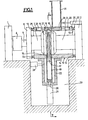
- the illustrated device for pressing hollow tiles from a mixture of dry plaster and gypsum powder comprises two fixed crossbeams 1, 2, installed on the floor.
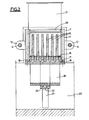
- the two crosspieces 1 and 2 are connected to each other at a distance above the ground, by two parallel horizontal tie rods 3 (see FIG. 2).
- the cylinder of a horizontal jack 4 is fixed to the face of the cross member 1 facing the cross member 2.
- the piston rod 5 of the jack 4 is fixed to one face of a mobile cross member 6 slidably mounted on the tie rods 3 by two lateral ears not shown.
- On the opposite face of the cross-member 6 is fixed, in alignment with the piston rod 5, a rod-spacer 7 carrying at its free end a vertical plate 8, of rectangular shape.
- a rod-spacer 9 aligned with the rod 7 and carrying at its free end a vertical plate 10 identical to the plate 8.
- stop blocks 13 are removably fixed to the opposite ends of the support 11, opposite the crosspieces 2 and 6.
- the support 11 has, in its lower horizontal wall 14, over the entire width, a rectangular transverse opening in which a horizontal cross member 15 is slidably mounted vertically.
- the cross member 15 is pierced with a row of vertical holes crossed by vertical cores 16 parallels extending upwards a short distance from the upper horizontal wall of the support 11.
- the lower ends of the cores 14 are integral with a horizontal crosspiece 17, the two ends of which are fixed at 18, for example using screw, on the underside of the wall 14.
- a U-shaped stirrup 19 receiving the cross-member 17 between its two branches is fixed by the ends of its two branches to the underside of the cross-member 15.
- the core of the stirrup 19 is integral with the piston rod 20 of a vertical cylinder 21 fixed by a support bracket 22 to the underside of the wall 14 of the support 11. All of the elements (bracket 19, cylinder 21, bracket 22) which project downwards on the bottom wall 14 of the support 11 are arranged in a pit 23.
- a horizontal jack 24 is interposed between the stirrup 22 and the wall of the pit 23 to move, perpendicular to the plane of the plates 8 and 10, the support 11 and all of the parts mounted on it. support.
- the cylinder 24 is controlled simultaneously with the cylinder 4 in the same direction as the latter, so that its piston rod moves at half the speed of the piston rod 5 of the cylinder 4 ..
- the upper horizontal wall of the support 11 has an opening extending over the entire width and over a large part of the length, so as to leave only two crosspieces 25 and 26 at the two ends of the support 11. Inside this opening are mounted with two slides 27 and 28 operated in opposition, perpendicular to the planes of the plates 8 and 10, by two jacks 29 and 30.
- a filling hopper 31 is mounted above the slide 28 so as to be mobile, under the action of a jack 32 mounted on the cross-member 2, relative to the slide 28, perpendicular to the planes of the plates / 8 and 10.
- the two slides 27 and 28 have at the bottom, at their opposite ends, a stepped profile so as to define together, when in contact with each other, a trapezoidal groove.
- the cross member 15 has for its part a complementary profile projecting upwards, in the form of a trapezoidal tongue.
- the two vertical lateral sides of the support 11 also have a hollow trapezoidal profile and the other a raised trapezoidal profile (see FIG. 2).
- These hollow and raised profiles form, on the edges of the tiles to be manufactured, tongues and grooves allowing the tiles to fit together during their assembly.
- the shims 13 determine the thickness of the tile to be manufactured.
- the change of the shims 13 therefore makes it possible to adapt the device in a simple and rapid manner to the production of tiles of different thicknesses.
- the cores 16 and the cross member 15 can also be changed in a simple manner.
- the cores 16 being fixed, it would also be possible to use retractable cores downwards and push the pressed tile back, after extraction of the cores, laterally outside the pressing cavity.
- one of the cheeks delimiting laterally the pressing cavity should be removable and the opposite cheek should be movable under the action of a jack so as to push the tile out of the cavity by the open side.
- the tiles when they are released from the pressing cavity, are practically stressed only in compression and in shear and not / not in. traction. This ensures a tear-free release and a self-cleaning effect on the surfaces delimiting the pressing cavity.
- the pressing mode according to the invention can also be used for the manufacture of solid tiles, without the use of cores, which simplifies the pressing device as regards parts 15, 17, 19 and 22.
Landscapes
- Engineering & Computer Science (AREA)
- Manufacturing & Machinery (AREA)
- Chemical & Material Sciences (AREA)
- Ceramic Engineering (AREA)
- Mechanical Engineering (AREA)
- Press-Shaping Or Shaping Using Conveyers (AREA)
Applications Claiming Priority (2)
| Application Number | Priority Date | Filing Date | Title |
|---|---|---|---|
| FR8401630 | 1984-02-02 | ||
| FR8401630A FR2559094B1 (fr) | 1984-02-02 | 1984-02-02 | Procede et dispositif de fabrication de carreaux, panneaux et elements de construction analogues par pressage d'un melange de poudre |
Publications (2)
| Publication Number | Publication Date |
|---|---|
| EP0150859A2 true EP0150859A2 (de) | 1985-08-07 |
| EP0150859A3 EP0150859A3 (de) | 1985-08-28 |
Family
ID=9300712
Family Applications (1)
| Application Number | Title | Priority Date | Filing Date |
|---|---|---|---|
| EP85101036A Withdrawn EP0150859A3 (de) | 1984-02-02 | 1985-02-01 | Verfahren und Vorrichtung zur Herstellung von Fliesen, Platten und ähnlichen Konstruktionsblöcken durch Pressen einer Pulvermischung |
Country Status (3)
| Country | Link |
|---|---|
| EP (1) | EP0150859A3 (de) |
| ES (1) | ES8605708A1 (de) |
| FR (1) | FR2559094B1 (de) |
Cited By (4)
| Publication number | Priority date | Publication date | Assignee | Title |
|---|---|---|---|---|
| US5154874A (en) * | 1990-03-14 | 1992-10-13 | Pro Mineral Gesellschaft Zur Verwendung Von Mineralstoffen Mbh | Method of producing gypsum/fiber board, especially for floor boards |
| EP0729926A1 (de) * | 1995-03-03 | 1996-09-04 | Gyproc Benelux | Verfahren zur Herstellung von Gipsbauteilen und nach diesem Verfahren hergestellte Gipsbauteile |
| CN118650705A (zh) * | 2024-08-19 | 2024-09-17 | 福建群峰机械有限公司 | 一种水沟槽成型机 |
| CN121246323A (zh) * | 2025-11-28 | 2026-01-02 | 汨罗市华先碳素有限公司 | 一种石墨压制成型装置 |
Family Cites Families (5)
| Publication number | Priority date | Publication date | Assignee | Title |
|---|---|---|---|---|
| DE157522C (de) * | ||||
| US2596602A (en) * | 1948-05-17 | 1952-05-13 | Jr Walter B Roddenbery | Molding machine |
| US2821005A (en) * | 1954-02-01 | 1958-01-28 | Davis Clarence Guy | Cement block making and forming press |
| FR1469851A (fr) * | 1966-02-22 | 1967-02-17 | Appareil destiné à la préfabrication par coulage en série d'élements de construction | |
| FR2220990A5 (en) * | 1973-03-05 | 1974-10-04 | Lambert Freres & Cie | Mould and method of mfg. plaster tiles - mould has pivotable sides and expandable base controlled by jacks |
-
1984
- 1984-02-02 FR FR8401630A patent/FR2559094B1/fr not_active Expired
-
1985
- 1985-02-01 ES ES540049A patent/ES8605708A1/es not_active Expired
- 1985-02-01 EP EP85101036A patent/EP0150859A3/de not_active Withdrawn
Cited By (4)
| Publication number | Priority date | Publication date | Assignee | Title |
|---|---|---|---|---|
| US5154874A (en) * | 1990-03-14 | 1992-10-13 | Pro Mineral Gesellschaft Zur Verwendung Von Mineralstoffen Mbh | Method of producing gypsum/fiber board, especially for floor boards |
| EP0729926A1 (de) * | 1995-03-03 | 1996-09-04 | Gyproc Benelux | Verfahren zur Herstellung von Gipsbauteilen und nach diesem Verfahren hergestellte Gipsbauteile |
| CN118650705A (zh) * | 2024-08-19 | 2024-09-17 | 福建群峰机械有限公司 | 一种水沟槽成型机 |
| CN121246323A (zh) * | 2025-11-28 | 2026-01-02 | 汨罗市华先碳素有限公司 | 一种石墨压制成型装置 |
Also Published As
| Publication number | Publication date |
|---|---|
| EP0150859A3 (de) | 1985-08-28 |
| FR2559094A1 (fr) | 1985-08-09 |
| ES540049A0 (es) | 1986-04-01 |
| FR2559094B1 (fr) | 1987-12-24 |
| ES8605708A1 (es) | 1986-04-01 |
Similar Documents
| Publication | Publication Date | Title |
|---|---|---|
| EP0196988B1 (de) | Form zum Herstellen von Verbundgegenständen | |
| EP0786939B1 (de) | Maschine zur automatischen herstellung von fleisch- und/oder gemüse-spiessen | |
| EP0619773B1 (de) | Verfahren und vorrichtung zum herstellen von baublöcken aus einem hydraulischen bindemittel wie gips, einem inerten material wie sand und wasser | |
| FR2559094A1 (fr) | Procede et dispositif de fabrication de carreaux, panneaux et elements de construction analogues par pressage d'un melange de poudre | |
| EP0202138B1 (de) | Verfahren zur Herstellung von Mauerblöcken, Anlage zur Durchführung dieses Verfahrens und daraus hergestellter Gegenstand | |
| EP0262278B1 (de) | Maschine zum Herstellen von Bausteinen aus stabilisierter Erde | |
| EP0263024B1 (de) | Vorrichtung zum Entformen und Handhaben von in befestigten Formen gegossenen Betongegenständen | |
| EP0006820B1 (de) | Verfahren zur Herstellung von Formteilen aus Holzteilchen, Vorrichtung zur Durchführung dieses Verfahrens und die hergestellten Formteile | |
| BE1014618A3 (fr) | Dispositif de fabrication de grands parpaings en beton a dimensions exactes. | |
| EP0140721A1 (de) | Einrichtung zum Formen von Betonerzeugnissen mit unverzüglicher Entformung | |
| JP2638572B2 (ja) | コンクリートブロック成形方法及びその型枠 | |
| FR2458338A1 (fr) | Procede pour compacter du sable de moulage et machine a mouler pour sa mise en oeuvre | |
| EP1260334B1 (de) | Verfahren und Vorrichtung zur Herstellung van Bauelementen | |
| FR2729602A1 (fr) | Procede de moulage sous pression, et installation pour la mise en oeuvre de ce procede | |
| EP0922548B1 (de) | Verfahren zum Herstellen von dünnen Platten aus einem giessbaren Material, insbesondere Gips, Vorrichtung zur Durchführung des Verfahrens und damit hergestelltes Produkt | |
| FR2493104A1 (fr) | Unite de moulage de produits charcutiers et dispositif pour sa mise en oeuvre | |
| FR2750915A1 (fr) | Procede de fabrication de panneaux en beton arme, panneau obtenu et installation de mise en oeuvre | |
| EP1818149A1 (de) | Verfahren zur Herstellung eines Betonträgerformwerkzeugs und entsprechender Betonträger | |
| EP0265301A1 (de) | Verfahren zur Herstellung eines Bauelementes aus Leichtbeton, das longitudinale und transversale Durchgänge enthält | |
| FR2517246A1 (fr) | Procede pour realiser des elements de constructions emboitables pour batiments | |
| EP0945230B1 (de) | Vorrichtung zum Schneiden von grossen Brotscheiben aus einem grossen Laib, sowie Verwendung der Vorrichtung. | |
| EP0050626B1 (de) | Verfahren und einrichtung zum kontinuierlichen herstellen von masseln aus nichteisen-metallen, die gestapelt werden sollen, ausgehend von einem rohling, gegossen mit hilfe eines giessrades, dessen giessrinne durch ein band geschlossen wird | |
| FR2528347A3 (fr) | Perfectionnement aux moules extensibles pour la fabrication d'elements de construction en platre | |
| FR2841818A1 (fr) | Procede, moule et dispositif de fabrication d'une piece perforee moulee en matiere composite | |
| BE558615A (de) |
Legal Events
| Date | Code | Title | Description |
|---|---|---|---|
| PUAI | Public reference made under article 153(3) epc to a published international application that has entered the european phase |
Free format text: ORIGINAL CODE: 0009012 |
|
| PUAL | Search report despatched |
Free format text: ORIGINAL CODE: 0009013 |
|
| AK | Designated contracting states |
Designated state(s): AT BE CH DE FR GB IT LI LU NL SE |
|
| AK | Designated contracting states |
Designated state(s): AT BE CH DE FR GB IT LI LU NL SE |
|
| 17P | Request for examination filed |
Effective date: 19860214 |
|
| 17Q | First examination report despatched |
Effective date: 19870504 |
|
| RAP3 | Party data changed (applicant data changed or rights of an application transferred) |
Owner name: LAMBERT INDUSTRIES, SOCIETE ANONYME DITE |
|
| STAA | Information on the status of an ep patent application or granted ep patent |
Free format text: STATUS: THE APPLICATION IS DEEMED TO BE WITHDRAWN |
|
| 18D | Application deemed to be withdrawn |
Effective date: 19890401 |
|
| RIN1 | Information on inventor provided before grant (corrected) |
Inventor name: BELLIER, M. MAURICE |