EP0150874A2 - Disjoncteur électrique à gaz comprimé d'extinction d'arc - Google Patents
Disjoncteur électrique à gaz comprimé d'extinction d'arc Download PDFInfo
- Publication number
- EP0150874A2 EP0150874A2 EP85200038A EP85200038A EP0150874A2 EP 0150874 A2 EP0150874 A2 EP 0150874A2 EP 85200038 A EP85200038 A EP 85200038A EP 85200038 A EP85200038 A EP 85200038A EP 0150874 A2 EP0150874 A2 EP 0150874A2
- Authority
- EP
- European Patent Office
- Prior art keywords
- movable
- movable body
- circuit breaker
- arc
- contact
- Prior art date
- Legal status (The legal status is an assumption and is not a legal conclusion. Google has not performed a legal analysis and makes no representation as to the accuracy of the status listed.)
- Granted
Links
- 239000012530 fluid Substances 0.000 title claims abstract description 29
- 238000005422 blasting Methods 0.000 claims abstract description 31
- 230000006835 compression Effects 0.000 claims abstract description 21
- 238000007906 compression Methods 0.000 claims abstract description 21
- 230000009471 action Effects 0.000 claims abstract description 18
- 239000007787 solid Substances 0.000 claims abstract description 7
- 239000011810 insulating material Substances 0.000 claims description 5
- 230000007246 mechanism Effects 0.000 claims description 4
- SFZCNBIFKDRMGX-UHFFFAOYSA-N sulfur hexafluoride Chemical compound FS(F)(F)(F)(F)F SFZCNBIFKDRMGX-UHFFFAOYSA-N 0.000 claims description 3
- 229960000909 sulfur hexafluoride Drugs 0.000 claims description 3
- 230000000694 effects Effects 0.000 description 6
- 238000010438 heat treatment Methods 0.000 description 4
- 238000010791 quenching Methods 0.000 description 4
- 230000000171 quenching effect Effects 0.000 description 4
- 238000000926 separation method Methods 0.000 description 3
- 208000036366 Sensation of pressure Diseases 0.000 description 2
- 230000008901 benefit Effects 0.000 description 2
- 230000015556 catabolic process Effects 0.000 description 2
- 230000001143 conditioned effect Effects 0.000 description 2
- 238000000354 decomposition reaction Methods 0.000 description 2
- 230000001771 impaired effect Effects 0.000 description 2
- 240000008042 Zea mays Species 0.000 description 1
- 235000005824 Zea mays ssp. parviglumis Nutrition 0.000 description 1
- 235000002017 Zea mays subsp mays Nutrition 0.000 description 1
- 230000008033 biological extinction Effects 0.000 description 1
- 230000015572 biosynthetic process Effects 0.000 description 1
- 230000003750 conditioning effect Effects 0.000 description 1
- 235000005822 corn Nutrition 0.000 description 1
- 230000003247 decreasing effect Effects 0.000 description 1
- 230000003111 delayed effect Effects 0.000 description 1
- 238000011038 discontinuous diafiltration by volume reduction Methods 0.000 description 1
- 230000006872 improvement Effects 0.000 description 1
- 239000002184 metal Substances 0.000 description 1
- 230000009467 reduction Effects 0.000 description 1
- 238000007493 shaping process Methods 0.000 description 1
Images


Classifications
-
- H—ELECTRICITY
- H01—ELECTRIC ELEMENTS
- H01H—ELECTRIC SWITCHES; RELAYS; SELECTORS; EMERGENCY PROTECTIVE DEVICES
- H01H33/00—High-tension or heavy-current switches with arc-extinguishing or arc-preventing means
- H01H33/70—Switches with separate means for directing, obtaining, or increasing flow of arc-extinguishing fluid
- H01H33/88—Switches with separate means for directing, obtaining, or increasing flow of arc-extinguishing fluid the flow of arc-extinguishing fluid being produced or increased by movement of pistons or other pressure-producing parts
- H01H33/90—Switches with separate means for directing, obtaining, or increasing flow of arc-extinguishing fluid the flow of arc-extinguishing fluid being produced or increased by movement of pistons or other pressure-producing parts this movement being effected by or in conjunction with the contact-operating mechanism
- H01H33/901—Switches with separate means for directing, obtaining, or increasing flow of arc-extinguishing fluid the flow of arc-extinguishing fluid being produced or increased by movement of pistons or other pressure-producing parts this movement being effected by or in conjunction with the contact-operating mechanism making use of the energy of the arc or an auxiliary arc
-
- H—ELECTRICITY
- H01—ELECTRIC ELEMENTS
- H01H—ELECTRIC SWITCHES; RELAYS; SELECTORS; EMERGENCY PROTECTIVE DEVICES
- H01H33/00—High-tension or heavy-current switches with arc-extinguishing or arc-preventing means
- H01H33/70—Switches with separate means for directing, obtaining, or increasing flow of arc-extinguishing fluid
- H01H33/88—Switches with separate means for directing, obtaining, or increasing flow of arc-extinguishing fluid the flow of arc-extinguishing fluid being produced or increased by movement of pistons or other pressure-producing parts
- H01H33/90—Switches with separate means for directing, obtaining, or increasing flow of arc-extinguishing fluid the flow of arc-extinguishing fluid being produced or increased by movement of pistons or other pressure-producing parts this movement being effected by or in conjunction with the contact-operating mechanism
- H01H33/901—Switches with separate means for directing, obtaining, or increasing flow of arc-extinguishing fluid the flow of arc-extinguishing fluid being produced or increased by movement of pistons or other pressure-producing parts this movement being effected by or in conjunction with the contact-operating mechanism making use of the energy of the arc or an auxiliary arc
- H01H2033/902—Switches with separate means for directing, obtaining, or increasing flow of arc-extinguishing fluid the flow of arc-extinguishing fluid being produced or increased by movement of pistons or other pressure-producing parts this movement being effected by or in conjunction with the contact-operating mechanism making use of the energy of the arc or an auxiliary arc with the gases from hot space and compression volume following different paths to arc space or nozzle, i.e. the compressed gases do not pass through hot volume
Definitions
- the object of the present invention is an electrical circuit breaker of the type using an arc extinguishing compressed fluid, in particular using a gas, such as sulphur hexafluoride.
- a known circuit breaker of this type (see e.g. the German Patent Application DE-OS 2.140.284) comprises, inside a tightly sealed casing filled with the arc extinguishing fluid, a current bearing connection with a stationary contact, a current bearing connection in which a movable contact is guided, being actuated by a driving mechanism, a blasting device consisting of a pis ton solid with the movable contact and defining a compression zone, and of a blasting nozzle brought by the movable contact to an advanced position relatively to the stationary contact with its opening communicating with said compression zone, as well as a body for the closure of the blasting nozzle slidingly mounted for a limited stroke on the stationary contact under the action of a spring, and suitable to be shifted against the action of said spring by said blasting nozzle when the same is moved together with the movable contact from its position of "circuit breaker open" to its position of "circuit breaker closed".
- both the station ary contact and the movable contact have been given a tubular shape for allowing the discharge of the gaseous stream, and as the movable contact bears a set of contact blades, the axial action of the gaseous stream which passes along the movable contact tends to shift the roots of the arc inside the tubular contact, with the consequent wear of the contact blades and of the main movable contact points.
- Purpose of the present invention is to provide an electrical circuit breaker of the type using an arc ex tinguishing compressed fluid as hereinbefore described, in which the extinguishment of the arc and hence the circuit breaking caused by the blast of the compressed extinguishing fluid takes place with higher safety and reliability, thanks to a higher energy made available for the extinguishment, and to a suitable orienting of the stream of compressed fluid against the arc stably positioned and conditioned as for its radial dimensions. and in which the mechanical energy requirement for the drive is limited, and the outside dimensions of the pole are reduced.
- an electrical circuit breaker is provided of the type as known from the DE-QS 2.140.284, in which the blasting nozzle closing body, slidingly mounted on the stationary contact and undergoing the action by a spring which tends to push it towards the free end of this con tact up to a stop, is provided with a cavity open towards the blasting nozzle, so as to be in communication with the opening of the nozzle itself, and through said opening, with the compression zone, and to behave as a collecting chamber for the fluid compressed by the action of said piston, and after the formation of the arc, by the action of said arc.
- the circuit breaker according to the invention due to the providing of said chamber in the movable bod y, couples therefore with the system of pneumatic compression of the extinguishing fluid, the system of pres sure self-generation by the action of the arc, and uses for quenching the arc itself the total energy accumulat ed in the collecting chamber, as a more efficient blast.
- a conditioning can be obtained of the radial dimensions of the arc for certain.values of the electrical current, with a containment effect of the e nergy developed by the arc, the positioning stability can be obtained of the arc between the two contacts, in side the zone in which the arc is developed, a suitable orienting can be obtained of the generated and compressed gas stream relatively to the arc, and the subduing is obtained of both arc roots to Concentrated fluid blast specific actions.
- the chamber provided in the movable body and the blasting volumes must be suitably;and correctly dimensioned to the purpose of achieving in the first part of the contact opening stroke, i.e., before the arc is formed due to the circuit opening, a reduction of the mechanical energy required from the driving unit and of exploiting later on, and precisely from the are forma tipn time on, in the most suitable way, the additional pressure generated by the arc in the chamber of the movable body.
- main contacts are provided, which are per se known, positioned in an area outside the nozzle and outside the chamber of the movable body, said main contacts being completely separated and independent from the arc contacts on which the movable bod y and the blasting nozzle are provided, their current bearing function being thus not impaired by the arc.
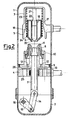
- circuit breaker according to the invention is being disclosed hereinunder in greater detail, with reference to the attached drawings, which illustrate an exemplifying embodiment of it, and some structural alter natives of a detail of it.
- drawings which illustrate an exemplifying embodiment of it, and some structural alter natives of a detail of it.
- each pole of the circuit breaker has the same structure as the one illustrated and disclosed hereinunder.
- the pole of the circuit breaker comprises an insulating casing 1, tightly sealed in its lower part by a box 2.
- the casing 1 contains an extinguishing fluid, in particular a gas, such as sulphur hexafluoride and is provided with current bearing connections 3 and 4.
- the upper connection 3 has the shape of a cup turned upside down, open downwards, and supports the main stationary contacts 5 and in its centre position a stationary rod shaped arc contact 6.
- a tubular stem 7 is supported and guided by means of a set of sliding blades, such stem being provided in its upper part with a movable arc contact 8 and with which a compression piston 9 being solid, which is tightly guided inside the cylindrical insulating casing 1.
- the main movable contacts 10 are applied for cooperating with the main stationary contacts 5.
- These main movable contacts 10 support inside themselves a blasting nozzle 11 of insulating material, said nozzle surrounding the free end of the tubular stem 7 with the movable arc contact 8, and protruding beyond this movable arc contact towards the stationary arc contact 6 (considering the opening position shown in fig. 2).
- the movable arc con tact 8 is capable of slidingly engaging the rod shaped stationary arc contact 6, whilst the lowest diameter of the opening of the blasting nozzle 11 is greater than the outer diameter of the rod shaped stationary arc con tact 6, so that, also in the "closed" position of the contacts, as shown in Fig.
- the tubular stem 7 is linked at its lower end, through an insulating connecting rod 14 and a metal lever 15 to a shaft 16 of a driving mechanism, such shaft ex tending outside the gas tight casing 1.
- a hollow body 17 is slidingly mounted of insulating material, which is provided in its inside with a guide sleeve ' 18, between which and the outer wall of the body an annular closed chamber 19 is formed, provided in its lower part with an opening 20 whose diameter is greater than the outer diameter of the rod shaped stationary arc. contact 6.
- a stop shoulder 21 is provided, with which an inner collar 22 of the guide sleeve 18 can coop erate for limiting the shift stroke of the body 17, under the thrust by a spring 23 acting between an annular out er shoulder 24 of the body, and the bottom of the cup forming the upper connection 3.
- the pi'ston 9 compresses the gas in the compression zone 13 communicating with the chamber 19 of the movable body 17, which chamber therefore collects compressed gas.
- the presence of the volume of chamber 19 reduces the value of the pres sure generated by the piston, and hence the mechanical energy required from the driving unit, which is control led by the dimensions of the chamber 19.
- the pressure surge generated by the arc and counter acting the compressing piston can also be reduced by intervening on the opening or bore of the blasting noz zle, increasing its diameter, with its extinguishing ef ficiency being not impaired, in that the fluid blast and pressure contribution of the movable body chamber is taken advantage of.
- the radial dimensions of the arc for particular valuesof electrical current to be interrupted are suit ably conditioned with a containment effect of the energy developed by the arc Moreover, a stability is obtained of positioning of the arc between the two arc contacts inside the zone inside which the arc develops.
- the configuration of the lower end of the movable body and of the blasting nozzle can be varied as for its shape, as well as for its dimensions, to the purpose of obtaining specific effects.
- the fluid blasting action on the arc results to be pre- vailigly directed in the axial sense and determines a gradual quenching of the arc.
- the shoulder 21 which limits the stroke of the movable hollow body 17 un der the thrust by the spring 23 can be placed in differ ent positions along the stationary arc contact 6, so as to define, at the end of said stroke of the movable bod y, different relative positionings between the end of the stationary arc contact 6 and the end of the mov able body 17. As it can be seen from a comparison between figs.
Landscapes
- Circuit Breakers (AREA)
- Driving Mechanisms And Operating Circuits Of Arc-Extinguishing High-Tension Switches (AREA)
- Toys (AREA)
- Surgical Instruments (AREA)
- Electrical Discharge Machining, Electrochemical Machining, And Combined Machining (AREA)
- Gas-Insulated Switchgears (AREA)
Priority Applications (1)
| Application Number | Priority Date | Filing Date | Title |
|---|---|---|---|
| AT85200038T ATE64796T1 (de) | 1984-01-20 | 1985-01-17 | Elektrischer schalter mit druckgas zum loeschen des lichtbogens. |
Applications Claiming Priority (2)
| Application Number | Priority Date | Filing Date | Title |
|---|---|---|---|
| IT1926484 | 1984-01-20 | ||
| IT19264/84A IT1173099B (it) | 1984-01-20 | 1984-01-20 | Interruttore elettrico a fluido compresso di estinzione dell'arco |
Publications (3)
| Publication Number | Publication Date |
|---|---|
| EP0150874A2 true EP0150874A2 (fr) | 1985-08-07 |
| EP0150874A3 EP0150874A3 (en) | 1988-06-01 |
| EP0150874B1 EP0150874B1 (fr) | 1991-06-26 |
Family
ID=11156239
Family Applications (1)
| Application Number | Title | Priority Date | Filing Date |
|---|---|---|---|
| EP85200038A Expired - Lifetime EP0150874B1 (fr) | 1984-01-20 | 1985-01-17 | Disjoncteur électrique à gaz comprimé d'extinction d'arc |
Country Status (7)
| Country | Link |
|---|---|
| US (1) | US4577073A (fr) |
| EP (1) | EP0150874B1 (fr) |
| AT (1) | ATE64796T1 (fr) |
| CA (1) | CA1249005A (fr) |
| DE (1) | DE3583299D1 (fr) |
| ES (1) | ES284263Y (fr) |
| IT (1) | IT1173099B (fr) |
Cited By (2)
| Publication number | Priority date | Publication date | Assignee | Title |
|---|---|---|---|---|
| FR2692414A1 (fr) * | 1992-06-10 | 1993-12-17 | Alsthom Gec | Contact pour disjoncteur. |
| EP1686602B2 (fr) † | 2005-02-01 | 2021-04-07 | ABB Power Grids Switzerland AG | Dispositif de montage d'un buse pour un disjoncteur électrique |
Families Citing this family (6)
| Publication number | Priority date | Publication date | Assignee | Title |
|---|---|---|---|---|
| FR2662540B1 (fr) * | 1990-05-23 | 1992-07-31 | Alsthom Gec | Disjoncteur a moyenne tension. |
| DE10207892B4 (de) * | 2002-02-20 | 2004-02-05 | Siemens Ag | Vakuumschaltröhre mit einem Schaltkontaktstück |
| FR2906642B1 (fr) * | 2006-09-29 | 2008-12-19 | Areva T & D Sa | Actionnement par came cylindrique des contacts d'une chambre de coupure a double mouvement. |
| FR2906929B1 (fr) * | 2006-10-09 | 2009-01-30 | Areva T & D Sa | Actionnement par des contacts d'une chambre de coupure a double mouvement par un tube isolant |
| WO2010112058A1 (fr) * | 2009-03-30 | 2010-10-07 | Abb Research Ltd | Disjoncteur |
| JP6478836B2 (ja) * | 2015-06-29 | 2019-03-06 | 株式会社東芝 | ガス遮断器 |
Family Cites Families (3)
| Publication number | Priority date | Publication date | Assignee | Title |
|---|---|---|---|---|
| US2933575A (en) * | 1956-10-22 | 1960-04-19 | Westinghouse Electric Corp | Circuit interrupters |
| DE2140284A1 (de) * | 1971-08-06 | 1973-02-15 | Siemens Ag | Elektrischer druckgasschalter |
| US4112276A (en) * | 1976-09-28 | 1978-09-05 | Westinghouse Electric Corp. | Compressed-gas circuit-interrupter having a sleeve-valve for temporarily blocking the orifice throat |
-
1984
- 1984-01-20 IT IT19264/84A patent/IT1173099B/it active
-
1985
- 1985-01-11 CA CA000471962A patent/CA1249005A/fr not_active Expired
- 1985-01-14 US US06/691,015 patent/US4577073A/en not_active Expired - Fee Related
- 1985-01-17 EP EP85200038A patent/EP0150874B1/fr not_active Expired - Lifetime
- 1985-01-17 DE DE8585200038T patent/DE3583299D1/de not_active Expired - Fee Related
- 1985-01-17 AT AT85200038T patent/ATE64796T1/de not_active IP Right Cessation
- 1985-01-18 ES ES1985284263U patent/ES284263Y/es not_active Expired
Cited By (2)
| Publication number | Priority date | Publication date | Assignee | Title |
|---|---|---|---|---|
| FR2692414A1 (fr) * | 1992-06-10 | 1993-12-17 | Alsthom Gec | Contact pour disjoncteur. |
| EP1686602B2 (fr) † | 2005-02-01 | 2021-04-07 | ABB Power Grids Switzerland AG | Dispositif de montage d'un buse pour un disjoncteur électrique |
Also Published As
| Publication number | Publication date |
|---|---|
| DE3583299D1 (de) | 1991-08-01 |
| EP0150874B1 (fr) | 1991-06-26 |
| ATE64796T1 (de) | 1991-07-15 |
| ES284263Y (es) | 1986-07-16 |
| CA1249005A (fr) | 1989-01-17 |
| US4577073A (en) | 1986-03-18 |
| EP0150874A3 (en) | 1988-06-01 |
| IT8419264A0 (it) | 1984-01-20 |
| IT1173099B (it) | 1987-06-18 |
| ES284263U (es) | 1986-01-01 |
Similar Documents
| Publication | Publication Date | Title |
|---|---|---|
| US4556767A (en) | Gas-blast circuit breaker | |
| US3985988A (en) | Electric circuit breaker assembly | |
| EP0150874A2 (fr) | Disjoncteur électrique à gaz comprimé d'extinction d'arc | |
| IE870775L (en) | Compressed dielectric gas circuit breaker | |
| US4650941A (en) | Compressed gas, high tension circuit breaker, with operating energy assisted by the thermal effect of the arc | |
| US4471188A (en) | Pneumatic puffer circuit breaker | |
| US5126516A (en) | Puffer-type medium or high tension circuit breaker | |
| US4276456A (en) | Double-flow puffer-type compressed-gas circuit-interrupter | |
| US4163131A (en) | Dual-compression gas-blast puffer-type interrupting device | |
| US4514605A (en) | Compressed gas circuit breaker | |
| US4604508A (en) | Electric circuit breaker of the type using an arc quenching fluid with pressure self-generating due to the breakdown of the fluid | |
| US4945197A (en) | High tension circuit breaker including a dielectric gas used for blasting | |
| US4649243A (en) | Double-acting, compressed gas, high tension circuit breaker with actuating energy assisted by the thermal effect of the arc | |
| CN216902710U (zh) | 具有烟火式激发装置的开关电器 | |
| US3991292A (en) | Dual compression puffer interrupter | |
| US4465910A (en) | Self-generating gas flow interrupter | |
| CA1087232A (fr) | Commutateur electrique a jets de gaz successifs | |
| US4992634A (en) | Medium tension gas blast circuit breaker | |
| JP2568304B2 (ja) | 自動吹付け式中電圧遮断器 | |
| US4228332A (en) | Gas pressure circuit interrupter | |
| US2240233A (en) | Gas blast circuit breaker | |
| EP0161036A2 (fr) | Disjoncteur haute tension avec dispositif d'extinction de l'arc utilisant l'auto-génération de la pression d'extinction | |
| JPS63152828A (ja) | 圧縮ガス遮断器 | |
| CA1097396A (fr) | Traduction non-disponible | |
| JP2577116B2 (ja) | 高圧又は中電圧の遮断器 |
Legal Events
| Date | Code | Title | Description |
|---|---|---|---|
| PUAI | Public reference made under article 153(3) epc to a published international application that has entered the european phase |
Free format text: ORIGINAL CODE: 0009012 |
|
| AK | Designated contracting states |
Designated state(s): AT BE CH DE FR GB LI LU NL SE |
|
| PUAL | Search report despatched |
Free format text: ORIGINAL CODE: 0009013 |
|
| AK | Designated contracting states |
Kind code of ref document: A3 Designated state(s): AT BE CH DE FR GB LI LU NL SE |
|
| 17P | Request for examination filed |
Effective date: 19881025 |
|
| 17Q | First examination report despatched |
Effective date: 19901029 |
|
| GRAA | (expected) grant |
Free format text: ORIGINAL CODE: 0009210 |
|
| RAP1 | Party data changed (applicant data changed or rights of an application transferred) |
Owner name: ABB SACE SPA |
|
| RAP1 | Party data changed (applicant data changed or rights of an application transferred) |
Owner name: ABB SACE S.P.A. |
|
| AK | Designated contracting states |
Kind code of ref document: B1 Designated state(s): AT BE CH DE FR GB LI LU NL SE |
|
| REF | Corresponds to: |
Ref document number: 64796 Country of ref document: AT Date of ref document: 19910715 Kind code of ref document: T |
|
| REF | Corresponds to: |
Ref document number: 3583299 Country of ref document: DE Date of ref document: 19910801 |
|
| ET | Fr: translation filed | ||
| PLBE | No opposition filed within time limit |
Free format text: ORIGINAL CODE: 0009261 |
|
| STAA | Information on the status of an ep patent application or granted ep patent |
Free format text: STATUS: NO OPPOSITION FILED WITHIN TIME LIMIT |
|
| 26N | No opposition filed | ||
| EPTA | Lu: last paid annual fee | ||
| EAL | Se: european patent in force in sweden |
Ref document number: 85200038.9 |
|
| PGFP | Annual fee paid to national office [announced via postgrant information from national office to epo] |
Ref country code: LU Payment date: 19951201 Year of fee payment: 12 |
|
| PGFP | Annual fee paid to national office [announced via postgrant information from national office to epo] |
Ref country code: FR Payment date: 19951215 Year of fee payment: 12 |
|
| PGFP | Annual fee paid to national office [announced via postgrant information from national office to epo] |
Ref country code: BE Payment date: 19951220 Year of fee payment: 12 |
|
| PGFP | Annual fee paid to national office [announced via postgrant information from national office to epo] |
Ref country code: GB Payment date: 19960108 Year of fee payment: 12 |
|
| PGFP | Annual fee paid to national office [announced via postgrant information from national office to epo] |
Ref country code: AT Payment date: 19960112 Year of fee payment: 12 |
|
| PGFP | Annual fee paid to national office [announced via postgrant information from national office to epo] |
Ref country code: DE Payment date: 19960126 Year of fee payment: 12 Ref country code: CH Payment date: 19960126 Year of fee payment: 12 |
|
| PGFP | Annual fee paid to national office [announced via postgrant information from national office to epo] |
Ref country code: SE Payment date: 19960130 Year of fee payment: 12 |
|
| PGFP | Annual fee paid to national office [announced via postgrant information from national office to epo] |
Ref country code: NL Payment date: 19960131 Year of fee payment: 12 |
|
| PG25 | Lapsed in a contracting state [announced via postgrant information from national office to epo] |
Ref country code: LU Free format text: LAPSE BECAUSE OF NON-PAYMENT OF DUE FEES Effective date: 19970117 Ref country code: GB Effective date: 19970117 Ref country code: AT Effective date: 19970117 |
|
| PG25 | Lapsed in a contracting state [announced via postgrant information from national office to epo] |
Ref country code: SE Effective date: 19970118 |
|
| PG25 | Lapsed in a contracting state [announced via postgrant information from national office to epo] |
Ref country code: LI Effective date: 19970131 Ref country code: CH Effective date: 19970131 Ref country code: BE Effective date: 19970131 |
|
| BERE | Be: lapsed |
Owner name: ABB SACE S.P.A. Effective date: 19970131 |
|
| PG25 | Lapsed in a contracting state [announced via postgrant information from national office to epo] |
Ref country code: NL Effective date: 19970801 |
|
| GBPC | Gb: european patent ceased through non-payment of renewal fee |
Effective date: 19970117 |
|
| REG | Reference to a national code |
Ref country code: CH Ref legal event code: PL |
|
| PG25 | Lapsed in a contracting state [announced via postgrant information from national office to epo] |
Ref country code: FR Effective date: 19970930 |
|
| NLV4 | Nl: lapsed or anulled due to non-payment of the annual fee |
Effective date: 19970801 |
|
| PG25 | Lapsed in a contracting state [announced via postgrant information from national office to epo] |
Ref country code: DE Effective date: 19971001 |
|
| EUG | Se: european patent has lapsed |
Ref document number: 85200038.9 |
|
| REG | Reference to a national code |
Ref country code: FR Ref legal event code: ST |