EP1686602B2 - Dispositif de montage d'un buse pour un disjoncteur électrique - Google Patents
Dispositif de montage d'un buse pour un disjoncteur électrique Download PDFInfo
- Publication number
- EP1686602B2 EP1686602B2 EP05405049.7A EP05405049A EP1686602B2 EP 1686602 B2 EP1686602 B2 EP 1686602B2 EP 05405049 A EP05405049 A EP 05405049A EP 1686602 B2 EP1686602 B2 EP 1686602B2
- Authority
- EP
- European Patent Office
- Prior art keywords
- insulating material
- material nozzle
- spring
- clamping
- ring
- Prior art date
- Legal status (The legal status is an assumption and is not a legal conclusion. Google has not performed a legal analysis and makes no representation as to the accuracy of the status listed.)
- Expired - Lifetime
Links
Images


Classifications
-
- H—ELECTRICITY
- H01—ELECTRIC ELEMENTS
- H01H—ELECTRIC SWITCHES; RELAYS; SELECTORS; EMERGENCY PROTECTIVE DEVICES
- H01H33/00—High-tension or heavy-current switches with arc-extinguishing or arc-preventing means
- H01H33/70—Switches with separate means for directing, obtaining, or increasing flow of arc-extinguishing fluid
- H01H33/7015—Switches with separate means for directing, obtaining, or increasing flow of arc-extinguishing fluid characterised by flow directing elements associated with contacts
- H01H33/7061—Switches with separate means for directing, obtaining, or increasing flow of arc-extinguishing fluid characterised by flow directing elements associated with contacts characterised by use of special mounting means
-
- H—ELECTRICITY
- H01—ELECTRIC ELEMENTS
- H01H—ELECTRIC SWITCHES; RELAYS; SELECTORS; EMERGENCY PROTECTIVE DEVICES
- H01H33/00—High-tension or heavy-current switches with arc-extinguishing or arc-preventing means
- H01H33/70—Switches with separate means for directing, obtaining, or increasing flow of arc-extinguishing fluid
- H01H33/7015—Switches with separate means for directing, obtaining, or increasing flow of arc-extinguishing fluid characterised by flow directing elements associated with contacts
- H01H33/7023—Switches with separate means for directing, obtaining, or increasing flow of arc-extinguishing fluid characterised by flow directing elements associated with contacts characterised by an insulating tubular gas flow enhancing nozzle
Definitions
- the invention relates to the field of high-voltage technology, in particular high-voltage switch technology in electrical energy distribution networks. It is based on an interrupter unit for a switching device and a switching device according to the preamble of the independent claims.
- a circuit breaker with a switch drive which moves the first arcing contact and which also drives the opposite second arcing contact via an auxiliary gear articulated to the insulating material nozzle.
- the insulating material nozzle has a bead or flange on the outer surface at its first end.
- a first clamping ring is pushed over the bead and is snapped into place behind it.
- a second clamping ring is attached to the nozzle end to prevent the first clamping ring from being unlocked.
- the auxiliary gear to be driven is attached to the second clamping ring.
- the nozzle is connected to the switch drive in that the nozzle again has a bead or flange at the force-introducing point, which is clamped and screwed between two massive force-transmitting components. This results in a voluminous holding device for fastening the nozzle to the components driven by the switch drive.
- the invention is based on the prior art U.S. 5,424,503 went out.
- a generic interrupter unit for an electrical switching device with a first, movable contact part with an insulating material nozzle and a second contact part is disclosed.
- the insulating material nozzle has a nose and is held there in the axial direction by the nominal current contact formed as a clamping bracket and is pressed against a carrier body.
- the clamping device also comprises a retaining ring which fixes the end of the nominal current contact on the carrier body by radial clamping.
- an electrical self-blowing switch is shown with an insulating material nozzle, which is pushed onto a holder and thus held in place by clamping.
- the insulating nozzle is constructed in two parts for a simplified assembly of the contacts in the switch and comprises a base body and an extension piece, both made of plastic. Conventionally, the extension piece was glued seamlessly to the base body. The extension piece is now connected to the base body in a removable or exchangeable manner, in that there is an external groove on the base body and an internal groove on the extension piece and an annular wedge engages in the internal groove and external groove.
- the ring-shaped wedge is soft and can be serrated on its inside to prevent it from slipping.
- the object of the present invention is to provide a simplified, more compact mounting of the insulating nozzle on a component that transmits the drive movement in a switching device with an insulating nozzle for blowing the arc. According to the invention, this object is achieved by the features of the independent claims.
- the invention consists in an interrupter unit for an electrical switching device for power supply networks, in particular a high-voltage switch, the switching device having a central axis and at least one first contact part with an insulating nozzle for blowing an arc and a second contact part, with at least one of the contact parts being movable by a switch drive
- a holding device for connecting the insulating material nozzle to a component of the interrupter unit that can be moved by the switch drive, the holding device also being a clamping device which creates a mechanical connection between the insulating material nozzle and the component by means of a clamp mount and without screwing.
- the clamping device reduces the machining of the insulating material nozzle to a minimum and there are no holes or slots in the insulating material nozzle. No additional fasteners or components are required.
- the clamping device is neither screwed nor fastened to the insulating material nozzle or to the component, but only creates an essentially positive and non-positive connection between the insulating material nozzle and the movable component by clamping or pressing together.
- the clamping device comprises a retaining ring which is supported on the component.
- the retaining ring ensures that the insulating material nozzle is fixed in an exact alignment coaxially to the central axis of the interrupter unit.
- the retaining ring fixes the insulating material nozzle in the axial direction by clamping, the retaining ring having a retaining surface for securing the insulating material nozzle against sliding out in a first axial direction.
- the embodiment according to claim 3 has the advantage that the nozzle made of insulating material can be installed in a simplified manner, particularly in switching devices with contact parts driven on both sides or with a shielding electrode that can be moved via an insulating nozzle.
- the embodiments according to the invention according to claims 1 and 2 with a retaining ring and groove have the advantage that the fastening of the insulating material nozzle on the buffer cylinder of the interrupter unit is extremely compact.
- This solution is particularly advantageous for buffer cylinders according to claim 5, which are made in so-called copper technology, i. H. by deforming very thin copper sheets or copper pipes or generally by deforming sheets or pipes made of other electrically conductive materials.
- Claims 11-13 relate to an electrical switching device with an arc interrupter unit as described above and with the advantages mentioned there.
- Fig. 1 shows for an electrical switching device 1, here an example of a circuit breaker, the arcing arc interrupter unit in a schematic and partial representation.
- the interrupter unit has a central axis 1 a and at least one first contact part 2 with an insulating material nozzle 4 for blowing an arc, as well as a second contact part 3.
- the contact parts 2, 3 are typically arranged concentrically with respect to the central axis 12. At least one of the contact parts 2, 3 can be moved by a switch drive (not shown).
- the first contact part 2 here comprises a first arcing contact 2a in the form of a contact tulip 2a and an externally arranged first rated current contact 2b in the form of a contact tube 2b, which is designed as a continuation of the wall 50 of a buffer cylinder 5.
- the buffer cylinder 5 has a heating volume 51 and a precompression volume 52, which are separated by a base 53 with a valve flap.
- the second contact part 3 here comprises a second arcing contact 3a in the form of a contact pin 3a and, on the outside, a second rated current contact 3b in the form of a contact tulip 3b.
- the insulating material nozzle 4 is attached, for example, to the first contact part 2 on the rated current contact 2b.
- Main nozzle 4 and auxiliary nozzle 6 delimit the heating channel 64.
- extinguishing gases flow from the buffer cylinder 5 through the heating channel 64 to the front opening of the main nozzle 4 and blow the arc.
- Fig. 2 shows conventional embodiments for attaching the main or insulating material nozzle 4 to the movable component 5, here the buffer cylinder 5.
- buffer cylinders 5 with a considerable wall thickness have been used, in which a bore 7, 8a was inserted in order to screw the insulating material nozzle 4 to the buffer cylinder wall 50 .
- the bore 7 can be guided directly into the insulating material nozzle 4 or into a mounting block 8, the mounting block 8 pressing onto the end face 41 of the insulating material nozzle 4 and thereby fixing it on one side.
- the insulating material nozzle 4 has an incision or recess 40 into which a projection or projection 20 in the rated current contact tube 2b engages and thereby also fixes the insulating material nozzle 4 on the other side.
- a holding device for connecting the insulating material nozzle 4 to a component 5 which can be moved by the switch drive; 13, 14 of the interrupter unit present, the holding device as a clamping device 9, 10, 11; 12 acts, which by clamping 9, 5a, 5b, 5c; 12, 13a, 13b, 13c and, without a screw connection, a mechanical connection between the insulating material nozzle 4 and the component 5; 13, 14 creates.
- the invention can be used at the first end on the switch drive side or at the second end of the insulating material nozzle 4 facing away from the switch drive.
- the clamping device preferably comprises 9, 10, 11; 12 a retaining ring 9, 12, which is supported on the component 5, 13 and fixes the insulating material nozzle 4 in the axial direction 91, 92 by clamping, the retaining ring 9, 12 ensuring that the insulating material nozzle 4 is fixed in an exact alignment coaxially to the central axis 1a.
- the term ring or ring-shaped in the following also includes ring segment or partially ring-shaped.
- the coaxial alignment is necessary because between the outer diameter D 2 of the arcing contact pin 3a and the inner diameter of the insulating nozzle 4 ( Fig. 1 ) a small distance tolerance of approximately 1 mm to a few mm over the entire length of the contact pin 3a in the nozzle 4 is to be maintained. Correspondingly small tolerances should be maintained in the coaxial alignment in order to reliably rule out any tilting of the arcing contact pin 3 a in the insulating material nozzle 4.
- the clamping device 9, 10, 11; 12 and / or the insulating material nozzle 4 can be rotated about the central axis 1a during assembly relative to the component 5, 13.
- Figures 3a, 3b shows a first embodiment in which the component 5 is a movable buffer cylinder 5 with a buffer cylinder wall 50, which has an inner groove 5a and the clamping device 9, 10, 11 comprises a spring locking ring 9, which by engaging in the inner groove 5a and protruding from the Inner groove 5a fixes the insulating material nozzle 4 radially inward on the buffer cylinder 5 and transmits a switch drive force acting in the axial direction 91, 92 from the buffer cylinder 5 to the insulating material nozzle 4.
- the protrusion ensures, in particular, that the spring locking ring 9 is mechanically connected to an end face of the insulating material nozzle 4 and exerts a retaining force on the end face.
- the groove depth or penetration depth T 1 of the inner groove 5 a in the buffer cylinder wall 5 should be selected to be smaller than a ring width B 1 of the spring locking ring 9 for this purpose.
- the buffer cylinder wall 50 is advantageously made from a sheet metal or tube, in particular a copper sheet or copper tube, and has a wall thickness of less than 7 mm, preferably less than 5 mm, particularly preferably less than 3.5 mm; and / or the inner groove 5a has a puncture depth T 1 in a range from 0.8 mm to 3.0 mm, preferably 1.0 mm to 2.0 mm, particularly preferably equal to 1.5 mm.
- a decisive advantage of the clamp fastening is that components 5 with walls 50 made of thin, possibly deformed metal sheets or tubes can be positively and non-positively connected to the insulating material nozzle 4 by pure clamp fastening.
- Such sheets or tubes are preferably made of copper. This so-called copper technology is detailed in the European patents EP 0 735 555 and EP 0 806 049 described.
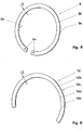
- Fig. 4 shows a Seeger ring 9, known per se, as a spring locking ring 9.
- the ring width B 1 is selected so that the aforementioned front retaining surface 9a and clamping surface 9b are large enough to absorb and transmit the clamping forces.
- the Seeger ring 9 is pulled together with special pliers engaging in the holes 9c, inserted in the axial direction 92 into the buffer cylinder 5 and snaps into the inner groove 5a in the buffer cylinder wall 50.
- Figures 3a, 3b also contains a further exemplary embodiment in which the clamping device 9, 10, 11 comprises an annular spring element 11 which can be resilient in the axial direction 92 and which is arranged between the spring locking ring 9 and the insulating material nozzle 4, in particular there in a recess 42 of the insulating material nozzle 4.
- the spring element 11 can be, for example, a commercially available O-ring 11, a spiral spring, a wave spring or a plate spring for generating an axial spring force.
- the inner groove 5a can have a chamfer 5c for the injury-free insertion of the spring element 11.
- the spring element 11 creates an axial and transverse tolerance of the component 1 and the insulating material nozzle 4 during assembly and at the same time brings about an exact alignment of the nozzle 4.
- a further improvement is achieved when an annular protective element 10, preferably a washer 10, for mechanical and thermal protection of the spring element 11 and the insulating material nozzle 4 is arranged between the spring locking ring 9 and the spring element 11 and is supported on a dimensionally stable projection 43 of the insulating material nozzle 4 .
- the interaction of the protective element 10 with the dimensionally stable, force-absorbing projection 43 ensures that no permanent deformation of the Teflon material of the insulating material nozzle 4 occurs under the contact pressure.
- the protective element 10 can be integrated into the clamping device 9, 10, 11, in particular into the spring locking ring 9 (not shown).
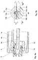
- Figures 5a, 5b shows a second embodiment in which the clamping device 12 has a second retaining surface 12d for securing the insulating material nozzle 4 against sliding out in a second axial direction 92 opposite to the first axial direction 91 and / or the clamping device 12 has a second clamping surface 12c for supporting the clamping device 12 the component 13 in the opposite second axial direction 92.
- the movable component 13, 14 can be a coupling element 13 act for a movable part 14 to be driven, in particular for a movable shielding electrode or for an auxiliary gear 14 of the switch drive.
- the coupling element 13 has an inner groove 13a and the insulating material nozzle 4 has an outer groove 44, and the clamping device 12 comprises a spring locking ring 12, which engages in the inner groove 13a and the outer groove 44 at the same time in the manner of a snap lock.
- the groove depth or puncture depth T 2 of the inner groove 13a is selected to be smaller than the ring width B 2 of the snap lock 12.
- the spring locking ring 12 or snap lock 12 replaces a conventional assembly in which the two parts 4, 13 are connected to one another via a thread.
- the snap lock 12 has the advantage of a simple, form-fitting and force-fitting assembly and a connection rotatable during assembly, through which, for. B. the rack 14 can be brought into a suitable position for the transmission.
- the moving contact 2 or buffer cylinder 5 can alternatively be brought into any azimuthal position, so that the contact 2 can be aligned with one of the phase connections which are arranged inclined to the outside.
- Fig. 6 shows an embodiment of such a spring locking ring 12.
- the spring locking ring 12 can be a ring segment 12 with an arc length in the range from 180 ° to 280 °, preferably 200 ° to 250 °, particularly preferably 230 °.
- the area is limited upwards or downwards by a sufficient expandability or a sufficient radial clamping effect of the spring locking ring 12 in the assembled state.
- the spring locking ring 12 should therefore be able to be bent open and introduced radially from the outside into the outer groove 44.
- the spring locking ring 12 should also be able to be pressed completely into the outer groove 44 when the component 13, 14 is pushed on.
- the groove depth or penetration depth T 3 of the outer groove 13a is selected to be deeper than the ring width B 2 of the snap lock 12.
- the spring locking ring 12 should also spring back into the inner groove 13a or be able to snap into place by means of an elastic restoring force.
- the spring locking ring 12 is made of an elastic material such as. B. be made of spring steel.
- the invention also relates to an electrical switching device for a power supply network, in particular a switching device with a movable insulating material nozzle 4 for blowing the arc, for example a high-voltage switch, high-current switch or circuit breaker, which has the interrupter unit described above.
- the insulating material nozzle 4 can be connected to a movable component 5, 13, 14 on both sides by a clamping device 9, 10, 11; 12 be connected, both clamping devices 9, 10, 11; 12 by clamping bracket 9, 5a, 5b, 5c; 12, 13a, 13b, 13c and without screwing each create a positive and non-positive connection between the insulating material nozzle 4 and the associated component 5, 13, 14.
- a first clamping device 9, 10, 11 for mechanically connecting the insulating material nozzle 4 to a movable buffer cylinder 5 of the interrupter unit
- a second clamping device 12 for mechanically connecting the insulating material nozzle 4 to a coupling element 13 for a part 14 of the interrupter unit to be driven.
- the part 14 to be driven can be a movable shielding electrode or an auxiliary gear 14, e.g. B. for a contact system 2, 3 driven on both sides.
Landscapes
- Circuit Breakers (AREA)
Claims (13)
- Unité d'interruption pour un appareil de commutation électrique (1) pour des réseaux de distribution d'énergie, notamment un commutateur à haute tension (1), l'appareil de commutation (1) présentant un axe central (1a) et au moins une première partie de contact (2) munie d'une buse en matériau isolant (4) pour souffler un arc électrique, et une deuxième partie de contact (3), au moins l'une des parties de contact (2, 3) pouvant être déplacée par un mécanisme d'entraînement de commutateur, dans laquelle un dispositif de maintien destiné à relier la buse en matériau isolant (4) avec un composant (5 ; 13, 14) de l'unité d'interruption pouvant être déplacé par le mécanisme d'entraînement de commutateur est présent, le dispositif de maintien étant en outre un dispositif de serrage (9, 10, 11 ; 12) qui, par maintien serré (9, 5a, 5b, 5c ; 12, 13a, 13b, 13c) et sans vissage, réalise une liaison mécanique entre la buse en matériau isolant (4) et le composant (5 ; 13, 14), le dispositif de serrage (9, 10, 11 ; 12) comprenant en outre une bague de maintien (9, 12) qui s'appuie sur le composant (5, 13) et assure une fixation de la buse en matériau isolant (4) dans une orientation coaxiale précise par rapport à l'axe central (1a), la bague de maintien (9, 12) fixant la buse en matériau isolant (4) dans la direction axiale (91, 92) par serrage, et la bague de maintien (9, 12) présentant une surface de retenue (9a, 12a) pour bloquer la buse en matériau isolant (4) afin qu'elle ne puisse pas sortir en glissant dans une première direction axiale (91),
caractérisée en ce quea) le composant (5) est un vérin d'amortissement (5) muni d'une paroi de vérin d'amortissement (50) qui présente une rainure intérieure (5a), etb) le dispositif de serrage (9, 10, 11) comprend un circlip ressort (9) qui fixe la buse en matériau isolant (4) sur le vérin d'amortissement (5) en venant en prise dans la rainure intérieure (5a) et en faisant saillie hors de la rainure intérieure (5a) radialement vers l'intérieur, et transmet du vérin d'amortissement (5) à la buse en matériau isolant (4) une force d'entraînement de commutateur agissant dans le sens axial (91, 92), etc) le dispositif de serrage (9, 10, 11) comprend un élément ressort (11) annulaire, pouvant être fléchi dans le sens axial (92) et qui est disposé entre le circlip ressort (9) et la buse en matériau isolant (4). - Unité d'interruption pour un appareil de commutation électrique (1) pour réseaux de distribution d'énergie, notamment un commutateur à haute tension (1), l'appareil de commutation (1) présentant un axe central (1a) et au moins une première partie de contact (2) munie d'une buse en matériau isolant (4) pour souffler un arc électrique, et une deuxième partie de contact (3), au moins l'une des parties de contact (2, 3) pouvant être déplacée par un mécanisme d'entraînement de commutateur, dans laquelle un dispositif de maintien destiné à relier la buse en matériau isolant (4) avec un composant (5 ; 13, 14) de l'unité d'interruption pouvant déplacé par le mécanisme d'entraînement de commutateur est présent, le dispositif de maintien étant en outre un dispositif de serrage (9, 10, 11 ; 12) qui, par maintien serré (9, 5a, 5b, 5c ; 12, 13a, 13b, 13c) et sans vissage, réalise une liaison mécanique entre la buse en matériau isolant (4) et le composant (5 ; 13, 14), le dispositif de serrage (9, 10, 11 ; 12) comprenant en outre une bague de maintien (9, 12) qui s'appuie sur le composant (5, 13) et assure une fixation de la buse en matériau isolant (4) dans une orientation coaxiale précise par rapport à l'axe central (1a), la bague de maintien (9, 12) fixant la buse en matériau isolant (4) dans la direction axiale (91, 92) par serrage, et la bague de maintien (9, 12) présentant une surface de retenue (9a, 12a) pour bloquer la buse en matériau isolant (4) afin qu'elle ne puisse pas sortir en glissant dans une première direction axiale (91),
caractérisée en ce quea) le composant (5) est un vérin d'amortissement (5) muni d'une paroi de vérin d'amortissement (50) qui présente une rainure intérieure (5a), etb) le dispositif de serrage (9, 10, 11) comprend un circlip ressort (9) qui fixe la buse en matériau isolant (4) sur le vérin d'amortissement (5) en venant en prise dans la rainure intérieure (5a) et en faisant saillie hors de la rainure intérieure (5a) radialement vers l'intérieur et transmet du vérin d'amortissement (5) à la buse en matériau isolant (4) une force d'entraînement de commutateur agissant dans le sens axial (91, 92), etc) la paroi de vérin d'amortissement (50) est fabriquée dans une tôle ou un tube et présente une épaisseur de paroi inférieure à 7 mm. - Unité d'interruption selon la revendication 1 ou 2, caractérisée en ce que, lors du montage, le dispositif de serrage (9, 10, 11 ; 12) et/ou la buse en matériau isolant (4) sont pivotants autour de l'axe central (1a) par rapport au composant (5, 13).
- Unité d'interruption selon l'une quelconque des revendications précédentes, caractérisée en ce que le dispositif de serrage (9, 10, 11 ; 12), notamment la bague de retenue (9, 12), présente une surface de serrage (9b, 12b) pour supporter le dispositif de serrage (9, 10, 11 ; 12) sur le composant (5 ; 13, 14) dans le premier sens axial (91).
- Unité d'interruption selon l'une quelconque des revendications précédentes, caractérisée en ce quea) la paroi de vérin d'amortissement (50) est fabriquée dans une tôle ou un tube, notamment une tôle de cuivre ou un tube en cuivre, et présente une épaisseur de paroi inférieure à 5 mm, notamment inférieure à 3,5 mm, et/oub) la rainure intérieure (5a) présente une profondeur d'entaille (T1) comprise dans une plage de 0,8 mm à 3,0 mm, de préférence de 1,0 mm à 2,0 mm, notamment de préférence égale à 1,5 mm.
- Unité d'interruption selon l'une quelconque des revendications précédentes, caractérisée en ce quea) l'élément ressort (11) est disposé entre le circlip ressort (9) et la buse en matériau isolant (4) dans un retrait (42) de la buse en matériau isolant (4), etb) notamment en ce que l'élément ressort (11) est un joint torique (11), un ressort en spirale, un ressort ondulé ou un ressort à disque destiné à produire une force de ressort axiale.
- Unité d'interruption selon la revendication 6, caractérisée en ce quea) un élément de protection annulaire (10), de préférence une rondelle (10), pour la protection mécanique et thermique de l'élément ressort (11) et de la buse en matériau isolant (4) est présent entre le circlip ressort (9) et l'élément ressort (11) et s'appuie sur une saillie indéformable (43) de la buse en matériau isolant (4), etb) notamment en ce que l'élément de protection (10) est intégré dans le dispositif de serrage (9, 10, 11), notamment dans le circlip ressort (9).
- Unité d'interruption selon l'une quelconque des revendications précédentes, caractérisée en ce quea) la rainure intérieure (5a) présente une surface d'appui (5b) destinée à interagir avec la surface de serrage (9b) revendiquée dans la revendication 3, et/oub) la rainure intérieure (5a) présente un biseautage (5c) destiné à l'introduction sans dommage de l'élément ressort (11).
- Unité d'interruption pour un appareil de commutation électrique (1) pour réseaux de distribution d'énergie, notamment un commutateur à haute tension (1), l'appareil de commutation (1) présentant un axe central (1a) et au moins une première partie de contact (2) munie d'une buse en matériau isolant (4) pour souffler un arc électrique, et une deuxième partie de contact (3), au moins l'une des parties de contact (2, 3) pouvant être déplacée par un mécanisme d'entraînement de commutateur, dans laquelle un dispositif de maintien destiné à relier la buse en matériau isolant (4) avec un composant (5 ; 13, 14) de l'unité d'interruption pouvant être déplacé par le mécanisme d'entraînement de commutateur est présent, le dispositif de maintien étant en outre un dispositif de serrage (9, 10, 11 ; 12) qui, par maintien serré (9, 5a, 5b, 5c ; 12, 13a, 13b, 13c) et sans vissage, réalise une liaison mécanique entre la buse en matériau isolant (4) et le composant (5 ; 13, 14), le dispositif de serrage (9, 10, 11 ; 12) comprenant en outre une bague de maintien (9, 12) qui s'appuie sur le composant (5, 13) et assure une fixation de la buse en matériau isolant (4) dans une orientation coaxiale précise par rapport à l'axe central (la), la bague de maintien (9, 12) fixant la buse en matériau isolant (4) dans la direction axiale (91, 92) par serrage, et la bague de maintien (9, 12) présentant une surface de retenue (9a, 12a) pour bloquer la buse en matériau isolant (4) afin qu'elle ne puisse pas sortir en glissant dans une première direction axiale (91),
caractérisée en ce quea) le composant (13, 14) est un élément d'accouplement (13) pour une électrode de blindage mobile ou pour un engrenage auxiliaire (14) du mécanisme d'entraînement de commutateur,b) l'élément d'accouplement (13) présente une rainure intérieure (13a), et la buse en matériau isolant (4) présente une rainure extérieure (44), etc) le dispositif de serrage (12) comprend un circlip ressort (12) qui vient en prise en même temps dans la rainure intérieure (13a) et la rainure extérieure (44) à la manière d'une fermeture à déclic. - Unité d'interruption selon la revendication 9, caractérisée en ce quea) le circlip ressort (12) est un segment d'anneau (12) ayant une longueur d'arc comprise dans la plage de 180° à 280°, de préférence de 200° à 250°, notamment de préférence égale à 230°, et/oub) le circlip ressort (12) peut être déplié et introduit radialement de l'extérieur dans la rainure extérieure (44), et/ouc) le circlip ressort (12) peut être entièrement enfoncé dans la rainure extérieure (44) lorsque le composant (13, 14) est emmanché, et peut s'enclencher dans la rainure intérieure (13a) par une force de rappel élastique, à l'état emmanché du composant (13, 14).
- Appareil de commutation électrique pour des réseaux de distribution d'énergie, notamment un appareil de commutation muni d'une buse en matériau isolant (4) mobile pour souffler un arc électrique, par exemple un commutateur à haute tension, un commutateur à courant fort ou un commutateur de puissance, caractérisé par une unité d'interruption selon l'une quelconque des revendications précédentes.
- Appareil de commutation électrique selon la revendication 11, caractérisé en ce quea) la buse en matériau isolant (4) est reliée des deux côtés à respectivement un composant mobile (5, 13, 14) par respectivement un dispositif de serrage (9, 10, 11 ; 12), etb) les deux dispositifs de serrage (9, 10, 11 ; 12) réalisent par maintien serré (9, 5a, 5b, 5c ; 12, 13a, 13b, 13c) et sans vissage, respectivement une liaison par complémentarité de forme et par adhérence entre la buse en matériau isolant (4) et le composant (5, 13, 14) associé.
- Appareil de commutation électrique selon la revendication 12, caractérisé en ce que les composants (5, 13, 14) sont un vérin d'amortissement mobile (5) et un élément d'accouplement (13) pour une partie à entraîner (14), notamment une électrode de blindage ou un engrenage auxiliaire, de l'unité d'interruption.
Priority Applications (5)
| Application Number | Priority Date | Filing Date | Title |
|---|---|---|---|
| EP05405049.7A EP1686602B2 (fr) | 2005-02-01 | 2005-02-01 | Dispositif de montage d'un buse pour un disjoncteur électrique |
| PCT/CH2006/000053 WO2006081697A1 (fr) | 2005-02-01 | 2006-01-25 | Fixation de tuyere pour un appareil de coupure electrique |
| CN2006800035521A CN101111915B (zh) | 2005-02-01 | 2006-01-25 | 用于电动开关装置的断续器单元 |
| JP2007552485A JP2008529223A (ja) | 2005-02-01 | 2006-01-25 | 電気的スイッチング装置のためのノズルの固定 |
| US11/879,508 US7619177B2 (en) | 2005-02-01 | 2007-07-18 | Nozzle fastening for electrical switching apparatus |
Applications Claiming Priority (1)
| Application Number | Priority Date | Filing Date | Title |
|---|---|---|---|
| EP05405049.7A EP1686602B2 (fr) | 2005-02-01 | 2005-02-01 | Dispositif de montage d'un buse pour un disjoncteur électrique |
Publications (3)
| Publication Number | Publication Date |
|---|---|
| EP1686602A1 EP1686602A1 (fr) | 2006-08-02 |
| EP1686602B1 EP1686602B1 (fr) | 2013-08-21 |
| EP1686602B2 true EP1686602B2 (fr) | 2021-04-07 |
Family
ID=34942898
Family Applications (1)
| Application Number | Title | Priority Date | Filing Date |
|---|---|---|---|
| EP05405049.7A Expired - Lifetime EP1686602B2 (fr) | 2005-02-01 | 2005-02-01 | Dispositif de montage d'un buse pour un disjoncteur électrique |
Country Status (5)
| Country | Link |
|---|---|
| US (1) | US7619177B2 (fr) |
| EP (1) | EP1686602B2 (fr) |
| JP (1) | JP2008529223A (fr) |
| CN (1) | CN101111915B (fr) |
| WO (1) | WO2006081697A1 (fr) |
Families Citing this family (10)
| Publication number | Priority date | Publication date | Assignee | Title |
|---|---|---|---|---|
| CN102714112B (zh) * | 2010-02-04 | 2016-01-27 | 三菱电机株式会社 | 气体断路器 |
| JP5047406B1 (ja) * | 2012-03-16 | 2012-10-10 | 三菱電機株式会社 | ガス遮断器 |
| TW201442051A (zh) * | 2013-03-08 | 2014-11-01 | Hitachi Ltd | 氣體斷路器 |
| US9054447B1 (en) | 2013-11-14 | 2015-06-09 | Reliance Controls Corporation | Electrical connector using air heated by an electrical arc during disengagement of contacts to extinguish the electrical arc |
| DE102013223632A1 (de) | 2013-11-20 | 2015-05-21 | Siemens Aktiengesellschaft | Schaltanordnung sowie Verfahren zur Montage einer Schaltanordnung |
| CN104289349B (zh) * | 2014-09-16 | 2016-08-24 | 宁波高新区甬港现代消防设计研究院有限公司 | 一种喷嘴安装工具 |
| JP6478836B2 (ja) | 2015-06-29 | 2019-03-06 | 株式会社東芝 | ガス遮断器 |
| JP2019075194A (ja) * | 2017-10-12 | 2019-05-16 | 株式会社日立製作所 | ガス遮断器 |
| JP6940437B2 (ja) * | 2018-03-13 | 2021-09-29 | アズビル株式会社 | 電磁流量計 |
| EP3618088A1 (fr) * | 2018-08-30 | 2020-03-04 | ABB Schweiz AG | Buse pour disjoncteur haute ou moyenne tension |
Citations (8)
| Publication number | Priority date | Publication date | Assignee | Title |
|---|---|---|---|---|
| DE2733551A1 (de) † | 1977-07-25 | 1979-02-08 | Siemens Ag | Druckgasschalter |
| DE3009165A1 (de) † | 1979-10-18 | 1981-04-30 | Sprecher & Schuh AG, 5001 Aarau, Aargau | Druckgasschalter |
| EP0150874A2 (fr) † | 1984-01-20 | 1985-08-07 | ABB SACE S.p.A. | Disjoncteur électrique à gaz comprimé d'extinction d'arc |
| WO1996021234A1 (fr) † | 1994-12-29 | 1996-07-11 | Asea Brown Boveri Ab | Disjoncteur a haute tension |
| EP0735555A2 (fr) † | 1995-03-30 | 1996-10-02 | Asea Brown Boveri Ab | Disjoncteur à haute tension |
| DE19858793A1 (de) † | 1998-12-18 | 2000-06-21 | Alstom Energietechnik Gmbh | Druckgasschalter |
| DE19902835A1 (de) † | 1999-01-20 | 2000-08-17 | Siemens Ag | Hochspannungsleistungsschalter mit einer Isolierdüse |
| JP2003297198A (ja) † | 2002-04-05 | 2003-10-17 | Toshiba Corp | パッファ形ガス遮断器 |
Family Cites Families (5)
| Publication number | Priority date | Publication date | Assignee | Title |
|---|---|---|---|---|
| FR2093339A5 (fr) * | 1970-06-10 | 1972-01-28 | Merlin Gerin | |
| US3930133A (en) * | 1974-10-24 | 1975-12-30 | Quaker City Gear Works | Limit switch assembly |
| FR2696041B1 (fr) * | 1992-09-18 | 1994-10-14 | Alsthom Gec | Disjoncteur à éléments fixés par frettage. |
| DE29609909U1 (de) * | 1996-05-24 | 1996-08-22 | Siemens AG, 80333 München | Hochspannungs-Leistungsschalter mit einer Isolierstoffdüse |
| FR2767221B1 (fr) * | 1997-08-11 | 1999-09-10 | Gec Alsthom T & D Sa | Disjoncteur a auto-soufflage et a compression reduite |
-
2005
- 2005-02-01 EP EP05405049.7A patent/EP1686602B2/fr not_active Expired - Lifetime
-
2006
- 2006-01-25 CN CN2006800035521A patent/CN101111915B/zh not_active Expired - Lifetime
- 2006-01-25 JP JP2007552485A patent/JP2008529223A/ja not_active Withdrawn
- 2006-01-25 WO PCT/CH2006/000053 patent/WO2006081697A1/fr not_active Ceased
-
2007
- 2007-07-18 US US11/879,508 patent/US7619177B2/en not_active Expired - Lifetime
Patent Citations (8)
| Publication number | Priority date | Publication date | Assignee | Title |
|---|---|---|---|---|
| DE2733551A1 (de) † | 1977-07-25 | 1979-02-08 | Siemens Ag | Druckgasschalter |
| DE3009165A1 (de) † | 1979-10-18 | 1981-04-30 | Sprecher & Schuh AG, 5001 Aarau, Aargau | Druckgasschalter |
| EP0150874A2 (fr) † | 1984-01-20 | 1985-08-07 | ABB SACE S.p.A. | Disjoncteur électrique à gaz comprimé d'extinction d'arc |
| WO1996021234A1 (fr) † | 1994-12-29 | 1996-07-11 | Asea Brown Boveri Ab | Disjoncteur a haute tension |
| EP0735555A2 (fr) † | 1995-03-30 | 1996-10-02 | Asea Brown Boveri Ab | Disjoncteur à haute tension |
| DE19858793A1 (de) † | 1998-12-18 | 2000-06-21 | Alstom Energietechnik Gmbh | Druckgasschalter |
| DE19902835A1 (de) † | 1999-01-20 | 2000-08-17 | Siemens Ag | Hochspannungsleistungsschalter mit einer Isolierdüse |
| JP2003297198A (ja) † | 2002-04-05 | 2003-10-17 | Toshiba Corp | パッファ形ガス遮断器 |
Also Published As
| Publication number | Publication date |
|---|---|
| US20070295693A1 (en) | 2007-12-27 |
| EP1686602B1 (fr) | 2013-08-21 |
| EP1686602A1 (fr) | 2006-08-02 |
| JP2008529223A (ja) | 2008-07-31 |
| CN101111915B (zh) | 2012-04-18 |
| US7619177B2 (en) | 2009-11-17 |
| CN101111915A (zh) | 2008-01-23 |
| WO2006081697A1 (fr) | 2006-08-10 |
Similar Documents
| Publication | Publication Date | Title |
|---|---|---|
| EP3639334B1 (fr) | Fixation a un rail de support | |
| EP1686602B2 (fr) | Dispositif de montage d'un buse pour un disjoncteur électrique | |
| DE102015120921B4 (de) | Steckverbinder und Steckerverbinderanordnung | |
| EP2325859A1 (fr) | Commutateur à haute tension isolé du gaz | |
| WO2007087733A1 (fr) | Chambre de commutation pour un interrupteur à haute tension isolé au gaz | |
| EP0394693B1 (fr) | Appareil de commutation de température | |
| EP1064664A1 (fr) | Sectionneur de puissance haute tension a buse isolante | |
| EP1224716A1 (fr) | Coupleur de connecteur coaxial | |
| EP3479391A1 (fr) | Dispositif de mise en court-circuit destiné à être utilisé dans des systèmes à basses et moyennes tensions pour la protection des biens et des personnes | |
| EP0786787B1 (fr) | Commutateur à poussoir autoréglable | |
| EP3494586B1 (fr) | Contact pour un disjoncteur haute tension et procédé de fabrication | |
| DE102008057223A1 (de) | Vorrichtung zum Überwachen des Zustandes einer Schutzeinrichtung einer Maschine | |
| DE29609909U1 (de) | Hochspannungs-Leistungsschalter mit einer Isolierstoffdüse | |
| EP3138113B1 (fr) | Prévention de défauts d'alignement d'une barre d'entraînement d'un disjoncteur | |
| DE10229095B4 (de) | Abschirmelektrode | |
| EP1037347B1 (fr) | Fixation rapide à encliquetage d'un appareil d'installation électrique sur un rail DIN | |
| EP2036105B1 (fr) | Actionneur pour l'actionnement d'un interrupteur de sécurité | |
| EP0297218A2 (fr) | Raccord enfichable | |
| DE102016205792A1 (de) | Elektrisches Steckerteil für eine Hochspannungs-Schaltstrecke und dessen Verwendung | |
| DE102018117612B4 (de) | Verbindungselement für Installationsschaltgeräte, mehrpolige Installationsschaltgeräteanordnung, Schaltschrank und Verfahren | |
| EP2184756B1 (fr) | Dispositif de surveillance de l'état d'un dispositif de protection d'une machine | |
| DE102017104495A1 (de) | Kontaktstecker für einen Trennschalter | |
| WO1997050106A1 (fr) | Mecanisme d'entrainement d'appareillages commutateurs a vide de haute tension | |
| DE19902910A1 (de) | Vorrichtung zum Schalten einer elektrischen Verbindung, insbesondere Schwenkhebelschalter | |
| WO2009138397A1 (fr) | Chambre de coupure |
Legal Events
| Date | Code | Title | Description |
|---|---|---|---|
| PUAI | Public reference made under article 153(3) epc to a published international application that has entered the european phase |
Free format text: ORIGINAL CODE: 0009012 |
|
| AK | Designated contracting states |
Kind code of ref document: A1 Designated state(s): AT BE BG CH CY CZ DE DK EE ES FI FR GB GR HU IE IS IT LI LT LU MC NL PL PT RO SE SI SK TR |
|
| AX | Request for extension of the european patent |
Extension state: AL BA HR LV MK YU |
|
| 17P | Request for examination filed |
Effective date: 20070117 |
|
| AKX | Designation fees paid |
Designated state(s): AT BE BG CH CY CZ DE DK EE ES FI FR GB GR HU IE IS IT LI LT LU MC NL PL PT RO SE SI SK TR |
|
| 17Q | First examination report despatched |
Effective date: 20090313 |
|
| GRAP | Despatch of communication of intention to grant a patent |
Free format text: ORIGINAL CODE: EPIDOSNIGR1 |
|
| INTG | Intention to grant announced |
Effective date: 20130503 |
|
| RIN1 | Information on inventor provided before grant (corrected) |
Inventor name: SAXL, DAVID Inventor name: VESTNER, MARKUS Inventor name: NORDSTROEM, THOMAS Inventor name: STROM, TOMAS Inventor name: BORG, TOMAS Inventor name: HUNGER, OLAF |
|
| GRAS | Grant fee paid |
Free format text: ORIGINAL CODE: EPIDOSNIGR3 |
|
| GRAA | (expected) grant |
Free format text: ORIGINAL CODE: 0009210 |
|
| AK | Designated contracting states |
Kind code of ref document: B1 Designated state(s): AT BE BG CH CY CZ DE DK EE ES FI FR GB GR HU IE IS IT LI LT LU MC NL PL PT RO SE SI SK TR |
|
| REG | Reference to a national code |
Ref country code: GB Ref legal event code: FG4D Free format text: NOT ENGLISH |
|
| REG | Reference to a national code |
Ref country code: DE Ref legal event code: R081 Ref document number: 502005013927 Country of ref document: DE Owner name: ABB SCHWEIZ AG, CH Free format text: FORMER OWNER: ABB RESEARCH LTD., ZUERICH, CH |
|
| REG | Reference to a national code |
Ref country code: CH Ref legal event code: EP |
|
| REG | Reference to a national code |
Ref country code: AT Ref legal event code: REF Ref document number: 628520 Country of ref document: AT Kind code of ref document: T Effective date: 20130915 |
|
| REG | Reference to a national code |
Ref country code: IE Ref legal event code: FG4D Free format text: LANGUAGE OF EP DOCUMENT: GERMAN |
|
| REG | Reference to a national code |
Ref country code: DE Ref legal event code: R096 Ref document number: 502005013927 Country of ref document: DE Effective date: 20131017 |
|
| REG | Reference to a national code |
Ref country code: NL Ref legal event code: VDEP Effective date: 20130821 |
|
| REG | Reference to a national code |
Ref country code: LT Ref legal event code: MG4D |
|
| PG25 | Lapsed in a contracting state [announced via postgrant information from national office to epo] |
Ref country code: PT Free format text: LAPSE BECAUSE OF FAILURE TO SUBMIT A TRANSLATION OF THE DESCRIPTION OR TO PAY THE FEE WITHIN THE PRESCRIBED TIME-LIMIT Effective date: 20131223 Ref country code: LT Free format text: LAPSE BECAUSE OF FAILURE TO SUBMIT A TRANSLATION OF THE DESCRIPTION OR TO PAY THE FEE WITHIN THE PRESCRIBED TIME-LIMIT Effective date: 20130821 Ref country code: IS Free format text: LAPSE BECAUSE OF FAILURE TO SUBMIT A TRANSLATION OF THE DESCRIPTION OR TO PAY THE FEE WITHIN THE PRESCRIBED TIME-LIMIT Effective date: 20131221 Ref country code: CY Free format text: LAPSE BECAUSE OF FAILURE TO SUBMIT A TRANSLATION OF THE DESCRIPTION OR TO PAY THE FEE WITHIN THE PRESCRIBED TIME-LIMIT Effective date: 20130710 Ref country code: SE Free format text: LAPSE BECAUSE OF FAILURE TO SUBMIT A TRANSLATION OF THE DESCRIPTION OR TO PAY THE FEE WITHIN THE PRESCRIBED TIME-LIMIT Effective date: 20130821 |
|
| PG25 | Lapsed in a contracting state [announced via postgrant information from national office to epo] |
Ref country code: FI Free format text: LAPSE BECAUSE OF FAILURE TO SUBMIT A TRANSLATION OF THE DESCRIPTION OR TO PAY THE FEE WITHIN THE PRESCRIBED TIME-LIMIT Effective date: 20130821 Ref country code: PL Free format text: LAPSE BECAUSE OF FAILURE TO SUBMIT A TRANSLATION OF THE DESCRIPTION OR TO PAY THE FEE WITHIN THE PRESCRIBED TIME-LIMIT Effective date: 20130821 Ref country code: GR Free format text: LAPSE BECAUSE OF FAILURE TO SUBMIT A TRANSLATION OF THE DESCRIPTION OR TO PAY THE FEE WITHIN THE PRESCRIBED TIME-LIMIT Effective date: 20131122 Ref country code: SI Free format text: LAPSE BECAUSE OF FAILURE TO SUBMIT A TRANSLATION OF THE DESCRIPTION OR TO PAY THE FEE WITHIN THE PRESCRIBED TIME-LIMIT Effective date: 20130821 |
|
| PG25 | Lapsed in a contracting state [announced via postgrant information from national office to epo] |
Ref country code: CY Free format text: LAPSE BECAUSE OF FAILURE TO SUBMIT A TRANSLATION OF THE DESCRIPTION OR TO PAY THE FEE WITHIN THE PRESCRIBED TIME-LIMIT Effective date: 20130821 |
|
| PG25 | Lapsed in a contracting state [announced via postgrant information from national office to epo] |
Ref country code: EE Free format text: LAPSE BECAUSE OF FAILURE TO SUBMIT A TRANSLATION OF THE DESCRIPTION OR TO PAY THE FEE WITHIN THE PRESCRIBED TIME-LIMIT Effective date: 20130821 Ref country code: CZ Free format text: LAPSE BECAUSE OF FAILURE TO SUBMIT A TRANSLATION OF THE DESCRIPTION OR TO PAY THE FEE WITHIN THE PRESCRIBED TIME-LIMIT Effective date: 20130821 Ref country code: DK Free format text: LAPSE BECAUSE OF FAILURE TO SUBMIT A TRANSLATION OF THE DESCRIPTION OR TO PAY THE FEE WITHIN THE PRESCRIBED TIME-LIMIT Effective date: 20130821 Ref country code: SK Free format text: LAPSE BECAUSE OF FAILURE TO SUBMIT A TRANSLATION OF THE DESCRIPTION OR TO PAY THE FEE WITHIN THE PRESCRIBED TIME-LIMIT Effective date: 20130821 Ref country code: RO Free format text: LAPSE BECAUSE OF FAILURE TO SUBMIT A TRANSLATION OF THE DESCRIPTION OR TO PAY THE FEE WITHIN THE PRESCRIBED TIME-LIMIT Effective date: 20130821 Ref country code: NL Free format text: LAPSE BECAUSE OF FAILURE TO SUBMIT A TRANSLATION OF THE DESCRIPTION OR TO PAY THE FEE WITHIN THE PRESCRIBED TIME-LIMIT Effective date: 20130821 |
|
| PG25 | Lapsed in a contracting state [announced via postgrant information from national office to epo] |
Ref country code: ES Free format text: LAPSE BECAUSE OF FAILURE TO SUBMIT A TRANSLATION OF THE DESCRIPTION OR TO PAY THE FEE WITHIN THE PRESCRIBED TIME-LIMIT Effective date: 20130821 Ref country code: IT Free format text: LAPSE BECAUSE OF FAILURE TO SUBMIT A TRANSLATION OF THE DESCRIPTION OR TO PAY THE FEE WITHIN THE PRESCRIBED TIME-LIMIT Effective date: 20130821 |
|
| PLBI | Opposition filed |
Free format text: ORIGINAL CODE: 0009260 |
|
| PLAB | Opposition data, opponent's data or that of the opponent's representative modified |
Free format text: ORIGINAL CODE: 0009299OPPO |
|
| PLAX | Notice of opposition and request to file observation + time limit sent |
Free format text: ORIGINAL CODE: EPIDOSNOBS2 |
|
| 26 | Opposition filed |
Opponent name: SIEMENS AKTIENGESELLSCHAFT Effective date: 20140520 |
|
| R26 | Opposition filed (corrected) |
Opponent name: SIEMENS AKTIENGESELLSCHAFT Effective date: 20140520 |
|
| REG | Reference to a national code |
Ref country code: DE Ref legal event code: R026 Ref document number: 502005013927 Country of ref document: DE Effective date: 20140520 |
|
| BERE | Be: lapsed |
Owner name: ABB TECHNOLOGY A.G. Effective date: 20140228 |
|
| PG25 | Lapsed in a contracting state [announced via postgrant information from national office to epo] |
Ref country code: LU Free format text: LAPSE BECAUSE OF FAILURE TO SUBMIT A TRANSLATION OF THE DESCRIPTION OR TO PAY THE FEE WITHIN THE PRESCRIBED TIME-LIMIT Effective date: 20140201 Ref country code: MC Free format text: LAPSE BECAUSE OF FAILURE TO SUBMIT A TRANSLATION OF THE DESCRIPTION OR TO PAY THE FEE WITHIN THE PRESCRIBED TIME-LIMIT Effective date: 20130821 |
|
| REG | Reference to a national code |
Ref country code: CH Ref legal event code: PL |
|
| GBPC | Gb: european patent ceased through non-payment of renewal fee |
Effective date: 20140201 |
|
| PG25 | Lapsed in a contracting state [announced via postgrant information from national office to epo] |
Ref country code: CH Free format text: LAPSE BECAUSE OF NON-PAYMENT OF DUE FEES Effective date: 20140228 Ref country code: LI Free format text: LAPSE BECAUSE OF NON-PAYMENT OF DUE FEES Effective date: 20140228 |
|
| REG | Reference to a national code |
Ref country code: IE Ref legal event code: MM4A |
|
| PLBB | Reply of patent proprietor to notice(s) of opposition received |
Free format text: ORIGINAL CODE: EPIDOSNOBS3 |
|
| PG25 | Lapsed in a contracting state [announced via postgrant information from national office to epo] |
Ref country code: IE Free format text: LAPSE BECAUSE OF NON-PAYMENT OF DUE FEES Effective date: 20140201 Ref country code: BE Free format text: LAPSE BECAUSE OF NON-PAYMENT OF DUE FEES Effective date: 20140228 Ref country code: GB Free format text: LAPSE BECAUSE OF NON-PAYMENT OF DUE FEES Effective date: 20140201 |
|
| REG | Reference to a national code |
Ref country code: AT Ref legal event code: MM01 Ref document number: 628520 Country of ref document: AT Kind code of ref document: T Effective date: 20140201 |
|
| PG25 | Lapsed in a contracting state [announced via postgrant information from national office to epo] |
Ref country code: AT Free format text: LAPSE BECAUSE OF NON-PAYMENT OF DUE FEES Effective date: 20140201 |
|
| REG | Reference to a national code |
Ref country code: FR Ref legal event code: PLFP Year of fee payment: 12 |
|
| PG25 | Lapsed in a contracting state [announced via postgrant information from national office to epo] |
Ref country code: BG Free format text: LAPSE BECAUSE OF FAILURE TO SUBMIT A TRANSLATION OF THE DESCRIPTION OR TO PAY THE FEE WITHIN THE PRESCRIBED TIME-LIMIT Effective date: 20130821 |
|
| PG25 | Lapsed in a contracting state [announced via postgrant information from national office to epo] |
Ref country code: TR Free format text: LAPSE BECAUSE OF FAILURE TO SUBMIT A TRANSLATION OF THE DESCRIPTION OR TO PAY THE FEE WITHIN THE PRESCRIBED TIME-LIMIT Effective date: 20130821 Ref country code: HU Free format text: LAPSE BECAUSE OF FAILURE TO SUBMIT A TRANSLATION OF THE DESCRIPTION OR TO PAY THE FEE WITHIN THE PRESCRIBED TIME-LIMIT; INVALID AB INITIO Effective date: 20050201 |
|
| APBM | Appeal reference recorded |
Free format text: ORIGINAL CODE: EPIDOSNREFNO |
|
| APBP | Date of receipt of notice of appeal recorded |
Free format text: ORIGINAL CODE: EPIDOSNNOA2O |
|
| APAH | Appeal reference modified |
Free format text: ORIGINAL CODE: EPIDOSCREFNO |
|
| APAW | Appeal reference deleted |
Free format text: ORIGINAL CODE: EPIDOSDREFNO |
|
| APAY | Date of receipt of notice of appeal deleted |
Free format text: ORIGINAL CODE: EPIDOSDNOA2O |
|
| APBM | Appeal reference recorded |
Free format text: ORIGINAL CODE: EPIDOSNREFNO |
|
| APBP | Date of receipt of notice of appeal recorded |
Free format text: ORIGINAL CODE: EPIDOSNNOA2O |
|
| APBQ | Date of receipt of statement of grounds of appeal recorded |
Free format text: ORIGINAL CODE: EPIDOSNNOA3O |
|
| REG | Reference to a national code |
Ref country code: FR Ref legal event code: PLFP Year of fee payment: 13 |
|
| REG | Reference to a national code |
Ref country code: DE Ref legal event code: R081 Ref document number: 502005013927 Country of ref document: DE Owner name: HITACHI ENERGY SWITZERLAND AG, CH Free format text: FORMER OWNER: ABB TECHNOLOGY AG, ZUERICH, CH Ref country code: DE Ref legal event code: R081 Ref document number: 502005013927 Country of ref document: DE Owner name: ABB SCHWEIZ AG, CH Free format text: FORMER OWNER: ABB TECHNOLOGY AG, ZUERICH, CH Ref country code: DE Ref legal event code: R081 Ref document number: 502005013927 Country of ref document: DE Owner name: ABB POWER GRIDS SWITZERLAND AG, CH Free format text: FORMER OWNER: ABB TECHNOLOGY AG, ZUERICH, CH Ref country code: DE Ref legal event code: R082 Ref document number: 502005013927 Country of ref document: DE Representative=s name: DENNEMEYER & ASSOCIATES S.A., DE Ref country code: DE Ref legal event code: R082 Ref document number: 502005013927 Country of ref document: DE Representative=s name: ZIMMERMANN & PARTNER PATENTANWAELTE MBB, DE |
|
| PLAB | Opposition data, opponent's data or that of the opponent's representative modified |
Free format text: ORIGINAL CODE: 0009299OPPO |
|
| R26 | Opposition filed (corrected) |
Opponent name: SIEMENS AKTIENGESELLSCHAFT Effective date: 20140520 |
|
| REG | Reference to a national code |
Ref country code: FR Ref legal event code: PLFP Year of fee payment: 14 |
|
| REG | Reference to a national code |
Ref country code: FR Ref legal event code: TP Owner name: ABB SCHWEIZ AG, CH Effective date: 20180912 |
|
| RAP2 | Party data changed (patent owner data changed or rights of a patent transferred) |
Owner name: ABB POWER GRIDS SWITZERLAND AG |
|
| PLAB | Opposition data, opponent's data or that of the opponent's representative modified |
Free format text: ORIGINAL CODE: 0009299OPPO |
|
| R26 | Opposition filed (corrected) |
Opponent name: SIEMENS AKTIENGESELLSCHAFT Effective date: 20140520 |
|
| APBU | Appeal procedure closed |
Free format text: ORIGINAL CODE: EPIDOSNNOA9O |
|
| PUAH | Patent maintained in amended form |
Free format text: ORIGINAL CODE: 0009272 |
|
| STAA | Information on the status of an ep patent application or granted ep patent |
Free format text: STATUS: PATENT MAINTAINED AS AMENDED |
|
| 27A | Patent maintained in amended form |
Effective date: 20210407 |
|
| AK | Designated contracting states |
Kind code of ref document: B2 Designated state(s): AT BE BG CH CY CZ DE DK EE ES FI FR GB GR HU IE IS IT LI LT LU MC NL PL PT RO SE SI SK TR |
|
| REG | Reference to a national code |
Ref country code: DE Ref legal event code: R102 Ref document number: 502005013927 Country of ref document: DE |
|
| REG | Reference to a national code |
Ref country code: DE Ref legal event code: R081 Ref document number: 502005013927 Country of ref document: DE Owner name: HITACHI ENERGY SWITZERLAND AG, CH Free format text: FORMER OWNER: ABB SCHWEIZ AG, BADEN, CH Ref country code: DE Ref legal event code: R081 Ref document number: 502005013927 Country of ref document: DE Owner name: HITACHI ENERGY LTD, CH Free format text: FORMER OWNER: ABB SCHWEIZ AG, BADEN, CH Ref country code: DE Ref legal event code: R082 Ref document number: 502005013927 Country of ref document: DE Representative=s name: DENNEMEYER & ASSOCIATES S.A., DE Ref country code: DE Ref legal event code: R081 Ref document number: 502005013927 Country of ref document: DE Owner name: ABB POWER GRIDS SWITZERLAND AG, CH Free format text: FORMER OWNER: ABB SCHWEIZ AG, BADEN, CH |
|
| REG | Reference to a national code |
Ref country code: DE Ref legal event code: R081 Ref document number: 502005013927 Country of ref document: DE Owner name: HITACHI ENERGY SWITZERLAND AG, CH Free format text: FORMER OWNER: ABB POWER GRIDS SWITZERLAND AG, BADEN, CH Ref country code: DE Ref legal event code: R081 Ref document number: 502005013927 Country of ref document: DE Owner name: HITACHI ENERGY LTD, CH Free format text: FORMER OWNER: ABB POWER GRIDS SWITZERLAND AG, BADEN, CH |
|
| P01 | Opt-out of the competence of the unified patent court (upc) registered |
Effective date: 20230527 |
|
| REG | Reference to a national code |
Ref country code: DE Ref legal event code: R082 Ref document number: 502005013927 Country of ref document: DE Representative=s name: DENNEMEYER & ASSOCIATES S.A., DE Ref country code: DE Ref legal event code: R081 Ref document number: 502005013927 Country of ref document: DE Owner name: HITACHI ENERGY LTD, CH Free format text: FORMER OWNER: HITACHI ENERGY SWITZERLAND AG, BADEN, CH |
|
| PGFP | Annual fee paid to national office [announced via postgrant information from national office to epo] |
Ref country code: DE Payment date: 20240219 Year of fee payment: 20 |
|
| PGFP | Annual fee paid to national office [announced via postgrant information from national office to epo] |
Ref country code: FR Payment date: 20240220 Year of fee payment: 20 |
|
| REG | Reference to a national code |
Ref country code: DE Ref legal event code: R071 Ref document number: 502005013927 Country of ref document: DE |