EP0150980B1 - Dispositif de chargement en papier pour imprimante - Google Patents
Dispositif de chargement en papier pour imprimante Download PDFInfo
- Publication number
- EP0150980B1 EP0150980B1 EP85300438A EP85300438A EP0150980B1 EP 0150980 B1 EP0150980 B1 EP 0150980B1 EP 85300438 A EP85300438 A EP 85300438A EP 85300438 A EP85300438 A EP 85300438A EP 0150980 B1 EP0150980 B1 EP 0150980B1
- Authority
- EP
- European Patent Office
- Prior art keywords
- platen
- paper
- paper bail
- operating member
- away
- Prior art date
- Legal status (The legal status is an assumption and is not a legal conclusion. Google has not performed a legal analysis and makes no representation as to the accuracy of the status listed.)
- Expired
Links
- 230000007935 neutral effect Effects 0.000 claims description 16
- 238000003780 insertion Methods 0.000 description 3
- 230000037431 insertion Effects 0.000 description 3
- 230000000977 initiatory effect Effects 0.000 description 2
- 230000000295 complement effect Effects 0.000 description 1
- 238000010276 construction Methods 0.000 description 1
- 238000010586 diagram Methods 0.000 description 1
- 230000000694 effects Effects 0.000 description 1
- 238000000034 method Methods 0.000 description 1
Images


Classifications
-
- B—PERFORMING OPERATIONS; TRANSPORTING
- B41—PRINTING; LINING MACHINES; TYPEWRITERS; STAMPS
- B41J—TYPEWRITERS; SELECTIVE PRINTING MECHANISMS, i.e. MECHANISMS PRINTING OTHERWISE THAN FROM A FORME; CORRECTION OF TYPOGRAPHICAL ERRORS
- B41J13/00—Devices or arrangements of selective printing mechanisms, e.g. ink-jet printers or thermal printers, specially adapted for supporting or handling copy material in short lengths, e.g. sheets
- B41J13/0009—Devices or arrangements of selective printing mechanisms, e.g. ink-jet printers or thermal printers, specially adapted for supporting or handling copy material in short lengths, e.g. sheets control of the transport of the copy material
- B41J13/0018—Devices or arrangements of selective printing mechanisms, e.g. ink-jet printers or thermal printers, specially adapted for supporting or handling copy material in short lengths, e.g. sheets control of the transport of the copy material in the sheet input section of automatic paper handling systems
-
- B—PERFORMING OPERATIONS; TRANSPORTING
- B41—PRINTING; LINING MACHINES; TYPEWRITERS; STAMPS
- B41J—TYPEWRITERS; SELECTIVE PRINTING MECHANISMS, i.e. MECHANISMS PRINTING OTHERWISE THAN FROM A FORME; CORRECTION OF TYPOGRAPHICAL ERRORS
- B41J13/00—Devices or arrangements of selective printing mechanisms, e.g. ink-jet printers or thermal printers, specially adapted for supporting or handling copy material in short lengths, e.g. sheets
- B41J13/02—Rollers
- B41J13/025—Special roller holding or lifting means, e.g. for temporarily raising one roller of a pair of nipping rollers for inserting printing material
-
- B—PERFORMING OPERATIONS; TRANSPORTING
- B41—PRINTING; LINING MACHINES; TYPEWRITERS; STAMPS
- B41J—TYPEWRITERS; SELECTIVE PRINTING MECHANISMS, i.e. MECHANISMS PRINTING OTHERWISE THAN FROM A FORME; CORRECTION OF TYPOGRAPHICAL ERRORS
- B41J13/00—Devices or arrangements of selective printing mechanisms, e.g. ink-jet printers or thermal printers, specially adapted for supporting or handling copy material in short lengths, e.g. sheets
- B41J13/10—Sheet holders, retainers, movable guides, or stationary guides
- B41J13/20—Bails
Definitions
- This invention relates to a paper loading device for a printer wherein a platen is rotated to feed paper wrapped therearound.
- Paper feeding means is already known wherein paper is held between a platen and pinch roller and is guided by a paper bail roller in a direction to be discharged from the platen.
- a paper bail roller In a paper feeding means of this type, when paper is to be manually inserted between a platen and a printing station, a paper bail roller must be manually moved away from and to the platen troublesomely. Particularly when cut sheet paper is used, the paper bail roller must be manually moved from and to the platen for each paper sheet, and such operations are very troublesome.
- U.S Patent 4 275 969 discloses use of an over-centre spring operated bail arm, however this only has limited possibilities for variation of its mode of operation.
- the present invention has for its object the solution of the problem of providing a paper feeding device which can be automatically operated by electromagnetic means, and has simple possibilities of manual override.
- a paper loading device for a printer, comprising: a platen connected to be rotated by a feed motor to feed paper; pinch rollers mounted for movement towards and away from said platen; a pair of left and right paper bail arms mounting a paper bail roller for rotation in opposing relation to said platen and mounted for pivotal motion to move said paper bail roller towards and away from said platen; an over-centre spring means for urging said paper bail arms towards and away from said platen on opposite sides of a neutral position of said paper bail arms; an operating member for controlling movement of said bail arms; and an electromagnetic actuating means displacing said operating member to provide movement of said paper bail arms; characterised in that said operating member comprises a stop to permit and constrain manual movement of the bail arms for release of pressure by the bail roller on the platen and is shaped to move the bail roller away from the platen on actuation of said electromagnetic means; and the device further comprises an operating lever which is shaped in relation to the shape of said operating member so that manual operation of said lever causes movement
- the paper bail arms may be stopped by said stopper of said operating member at a position on the opposite side of said neutral position provided by said toggle spring when said paper bail arms are manually operated to move said paper bail roller away from said platen.
- said paper bail arms may be returned to said position just forwardly of said neutral position.
- a second pressing portion may be formed on said manipulating lever for pressing said operating member to move said paper bail roller away from said platen when said manipulating lever is pivoted to move said pinch roller away from said platen.
- a manipulating lever may be provided for positioning the pinch roller.
- the spring means may be a toggle spring.
- support means may be provided for resiliently supporting said paper bail arms at a position a little beyond a neutral position provided by said spring means.
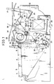
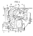
- Each of the side walls 1 has a recess 11 formed therein, and a pinch roller support plate 14 on which pinch rollers 12 and 13 are supported is supported at opposite ends thereof in the recesses 11 of the side walls 1 and is urged in a clockwise direction by a spring 15.
- a manipulating lever 17 is mounted for rotation on one of the side walls 1 by means of a pivot 18 and has an abutting face 16 which is opposed to a rear end of the pinch roller support plate 12.
- a pair of paper bail arms 20 on which a paper bail roller 19 is supported are mounted for pivotal motion on the left and right side walls 1 by means of pivots 21.
- Opposite hooks 25 of toggle springs 24 are hooked to pins 22 mounted on the paper bail arms 22 and pins 23 mounted on the corresponding side walls 1.
- An operating member 26 is mounted for pivotal motion around a pivot 28 on the one side wall 1 and is urged in a counterclockwise direction by a spring 27.
- the operating member 26 is connected to a plunger 30 of a solenoid 29 as an electromagnet secured to the side wall 1 and has formed thereon a pressing portion 32 for pressing against a projection 31 of one of the paper bail arms 20 and a stopper 34 for supporting a pin 33 mounted on the one paper bail arm 20.
- the manipulating lever 17 has formed thereon a second pressing portion 36 for pressing against a bent lug 35 formed at a rear portion of the operating member 28.
- a cover 38 having an opening 37 formed therein is located above the platen 2.
- a ROM 41 and a RAM 42 are connected to a CPU 40, and the wheel motor 6, the solenoid 29, a feed motor 43 coupled to the platen 2, and besides a carrier motor 44 for driving the carrier 5 are connected to the CPU 40 via an I/O interface 45.
- the feed motor 43 is turned on to rotate the platen 2 to feed the paper 39.
- a soft timer starts its operation.
- the feed motor 43 is turned off and the solenoid 29 is turned on after a time t1 has passed.
- the plunger 30 is retracted from the position as shown in Figure 1 to a position as shown in Figure 2 so that the operating member 26 is pivoted in the clockwise direction about the pivot 28 against the urging of the spring 27 to push, at the pressing portion 32 thereof, the paper bail arm 20 away from the platen 2.
- the paper bail arm 20 is stopped at a position just forwardly of a neutral position by the stopper 34 of the operating member 26 abutting with the pin 33 on the paper bail arm 20.
- the toggle spring 24 has a tendency to develop or expand the hooks 25 thereof from each other, and in the position of Figure 2, the pin 22 is positioned below a straight line linking the pivot 21 and the pin 13 so that the toggle spring 24 urges the paper bail arm 20 to the platen 2, that is, in the clockwise direction.
- the feed motor 43 is turned on so that the paper 39 inserted between the platen 2 and the paper pan 2a is fed under the guidance of the guide plate 10 of the carrier 5, by the platen 2 rotated by the motor 43 and cooperating with the pinch rollers 12 and 13.
- the feed motor 43 is turned off to end the automatic insertion or loading of the paper 39 and the solenoid 29 is turned off to allow the plunger 29 to move up so that the operating member 26 is returned in the counterclockwise direction by the force of the spring 27.
- an operator can, at the beginning of printing operation, automatically load paper 39 only by operation of a key.
- the paper bail arm 20 is pivoted to the platen 2 by the force of the toggle spring 24 to automatically hold the platen 2 with the paper bail roller 19 so that the paper 39 can be introduced certainly to the opening 37 of the cover 38 without being caught by a lower face of the cover 38.
- the stopper 34 holds the paper bail arm 20 to the position just forwardly of the neutral position and hence the paper bail arm 20 is held urged in the clockwise direction by a force, though weak, of the toggle spring 24.
- the feed motor 43 is energised for a period of time from t0 to t1 of Figure 7 and at the time t1 the solenoid 29 is turned on to move the paper bail roller 19 away from the platen 2 whereafter the feed motor 43 is energised again for a period of time from t2 to t3 to insert the paper 39, the feed motor 43 and the solenoid 29 may otherwise be energised for a period of time from t1 to t3 to insert the paper 39.
- the solenoid 29 is not energised before operation of the key for initiation of printing, and if in this condition the paper bail arm 20 is manually moved away from the platen 2, the paper bail arm 20 will be moved to a position a little beyond the neutral position and thereafter held thereto under an urging force of the toggle spring 24 acting in the counterclockwise direction.
- the solenoid will be energised for the period of time from t1 to t3 or from t0 to t3 as described hereinabove to pivot the operating member 26 in the clockwise direction so that the stopper 34 will press against the pin 33 to move the paper bail am 20 to the position a little displaced toward the platen 2 from the neutral position as seen in Figure 2.
- the paper bail roller 19 can be contacted with the platen 2 without fail, thereby preventing the paper 39 from being caught by the lower face of the cover 38.
- the pinch roller support plate 17 is pivoted in the clockwise direction around the recess 11 by the urging of the spring 15 to move the pinch rollers 12 and 13 away from the platen 2 while simultaneously the operating member 26 is returned to its initial position by the urging force of the spring 27 and the paper bail arm 20 is returned to the position adjacent the platen 2 by the force of the toggle spring 24.
- the paper bail roller 19 can be moved from and to the platen 2 in response to operations to move the pinch rollers 12 and 13 from and to the platen 2, a paper loading or inserting operation is very simple. This is very convenient when the pinch rollers 12 and 13 and the paper bail roller 19 are moved away from the platen 2 to make the paper 39 free.
Landscapes
- Handling Of Cut Paper (AREA)
Claims (7)
- Un dispositif de chargement de papier pour une imprimante, comprenant:
un cylindre (2), relié pour être mis en rotation par un moteur d'alimentation, pour faire avancer du papier ;
des rouleaux de pincement (12,13) montés pour se rapprocher et s'éloigner dudit cylindre ;
une paire de bras presse-papier gauche et droit (20), supportant un rouleau presse-papier (19) pour tourner en relation opposée dudit cylindre, et montée pour un mouvement de pivotement afin de rapprocher et éloigner ledit rouleau presse-papier dudit cylindre;
un moyen de ressort à détente brusque (24) pour pousser lesdits bras presse-papier en les éloignant ou en les rapprochant dudit cylindre sur les côtés opposés d'une position neutre desdits bras presse-papier ;
un élément de fonctionnement (26) pour commander le mouvement desdits bras presse-papier;
et un moyen d'actionnement électromagnétique (29) déplaçant ledit élément de fonctionnement pour donner un mouvement desdits bras de presse-papier;
caractérisé en ce que ledit élément de fonctionnement (26) comprend un arrêt (34) pour permettre et contraindre un mouvement manuel des bras presse-papier afin de relâcher la pression par le rouleau presse-papier (19) sur le cylindre (2), et qui est formé pour éloigner le rouleau presse-papier du cylindre lors de l'actionnement dudit moyen électromagnétique;
et le dispositif comprend, de plus, un levier de fonctionnement (17) qui est formé en rapport avec la forme dudit élément de fonctionnement de sorte qu'une action manuelle dudit levier provoque un mouvement d'éloignement des bras presse-papier du cylindre et, en même temps provoque un mouvement de mise hors contact des rouleaux de pincement avec ledit cylindre. - Un dispositif de chargement de papier pour une imprimante selon la revendication 1, dans lequel lesdits bras presse-papier sont arrêtés par ledit arrêt dudit élément de fonctionnement à une position sur le côté opposé de ladite position neutre fournie par ledit ressort articulé quand lesdits bras presse-papier sont actionnés manuellement pour éloigner ledit rouleau presse-papier dudit cylindre.
- Un dispositif de chargement de papier pour une imprimante selon la revendication 1 ou la revendication 2, dans lequel, dans la condition dans laquelle lesdits bras presse-papier sont arrêtés par ledit arrêt dudit élément de fonctionnement à une position sur le côté opposé de ladite position neutre fournie par ledit moyen de ressort quand lesdits bras presse-papier sont actionnés manuellement pour éloigner ledit rouleau presse-papier dudit cylindre, si ledit élément de fonctionnement est déplacé, lesdits bras presse-papier sont ramenés à ladite position juste en avant de ladite position neutre.
- Un dispositif de chargement de papier pour une imprimante comme revendiqué dans une revendication précédente quelconque, comprenant une seconde portion d'appui formée sur ledit levier de manoeuvre pour appuyer sur ledit élément de fonctionnement afin d'éloigner ledit rouleau presse-papier dudit cylindre, quand ledit levier de manoeuvre est pivoté pour éloigner ledit rouleau de pincement dudit cylindre.
- Un dispositif comme revendiqué dans une revendication précédente quelconque, comprenant un levier de manoeuvre pour mettre en position ledit rouleau de pincement.
- Un dispositif comme revendiqué dans une revendication précédente quelconque, dans lequel le moyen de ressort est un ressort articulé.
- Un dispositif comme revendiqué dans une revendication précédente quelconque, comprenant un moyen de support pour supporter de façon souple lesdits bras presse-papier à une position légèrement au-delà d'une position neutre fournie par ledit moyen de ressort.
Priority Applications (1)
| Application Number | Priority Date | Filing Date | Title |
|---|---|---|---|
| EP91200542A EP0435862B1 (fr) | 1984-01-25 | 1985-01-23 | Dispositif de chargement de papier |
Applications Claiming Priority (4)
| Application Number | Priority Date | Filing Date | Title |
|---|---|---|---|
| JP1162284A JPS60155479A (ja) | 1984-01-25 | 1984-01-25 | 印字機の用紙挿入装置 |
| JP11622/84 | 1984-01-25 | ||
| JP16870/84 | 1984-02-01 | ||
| JP1687084A JPS60161174A (ja) | 1984-02-01 | 1984-02-01 | 印字機の用紙自動挿入装置 |
Related Child Applications (1)
| Application Number | Title | Priority Date | Filing Date |
|---|---|---|---|
| EP91200542.8 Division-Into | 1985-01-23 |
Publications (3)
| Publication Number | Publication Date |
|---|---|
| EP0150980A2 EP0150980A2 (fr) | 1985-08-07 |
| EP0150980A3 EP0150980A3 (en) | 1988-04-27 |
| EP0150980B1 true EP0150980B1 (fr) | 1992-03-11 |
Family
ID=26347081
Family Applications (2)
| Application Number | Title | Priority Date | Filing Date |
|---|---|---|---|
| EP85300438A Expired EP0150980B1 (fr) | 1984-01-25 | 1985-01-23 | Dispositif de chargement en papier pour imprimante |
| EP91200542A Expired - Lifetime EP0435862B1 (fr) | 1984-01-25 | 1985-01-23 | Dispositif de chargement de papier |
Family Applications After (1)
| Application Number | Title | Priority Date | Filing Date |
|---|---|---|---|
| EP91200542A Expired - Lifetime EP0435862B1 (fr) | 1984-01-25 | 1985-01-23 | Dispositif de chargement de papier |
Country Status (4)
| Country | Link |
|---|---|
| US (1) | US4693621A (fr) |
| EP (2) | EP0150980B1 (fr) |
| CA (1) | CA1230352A (fr) |
| DE (2) | DE3587930T2 (fr) |
Families Citing this family (16)
| Publication number | Priority date | Publication date | Assignee | Title |
|---|---|---|---|---|
| US4787546A (en) * | 1986-03-07 | 1988-11-29 | General Scanning, Inc. | Apparatus for automatic threading of a web |
| JPS62208970A (ja) * | 1986-03-10 | 1987-09-14 | Minolta Camera Co Ltd | 印字装置 |
| DE3883872T2 (de) * | 1987-06-30 | 1994-02-10 | Seiko Epson Corp | Papierzuführvorrichtung für Drucker. |
| JPH02111576A (ja) * | 1988-10-20 | 1990-04-24 | Seikosha Co Ltd | 紙押え機構 |
| JP2676061B2 (ja) * | 1989-02-07 | 1997-11-12 | スター精密株式会社 | プリンタのベイル装置 |
| US5346322A (en) * | 1989-04-24 | 1994-09-13 | Brother Kogyo Kabushiki Kaisha | Printing device having paper feed control |
| JPH0342262A (ja) * | 1989-07-08 | 1991-02-22 | Brother Ind Ltd | 印字装置 |
| US5209590A (en) * | 1991-07-25 | 1993-05-11 | Star Micronics Co., Ltd. | Paper bailing apparatus for printer |
| DE69718768T2 (de) * | 1996-03-04 | 2003-10-16 | Copyer Co., Ltd. | Bilderzeugungsgerät |
| GB9710767D0 (en) * | 1996-06-26 | 1997-07-23 | On Ninh | Analgesic and anti-inflamatory compositions comprising domperidone and methods of using same |
| US5813781A (en) * | 1997-01-10 | 1998-09-29 | International Business Machines Corporation | Document feed roller opener and method therefor |
| ES2195688A1 (es) * | 2000-07-19 | 2003-12-01 | Investronica Sist S S A | Maquina de dibujo raster. |
| US7517163B1 (en) | 2008-07-25 | 2009-04-14 | International Business Machines Corporation | Pressure pad engagement mechanism using sliding actuator |
| JP5909372B2 (ja) * | 2012-01-19 | 2016-04-26 | 富士通コンポーネント株式会社 | プリンタ装置及びプリンタ装置の制御方法 |
| JP2017142299A (ja) * | 2016-02-08 | 2017-08-17 | 富士ゼロックス株式会社 | 画像形成装置 |
| CN111610087B (zh) * | 2020-06-04 | 2023-06-23 | 宝鸡市辉真建设工程质量检测有限责任公司 | 一种混凝土砖块成型后硬度测试设备 |
Family Cites Families (11)
| Publication number | Priority date | Publication date | Assignee | Title |
|---|---|---|---|---|
| US1478380A (en) * | 1923-12-25 | crawley | ||
| US3292762A (en) * | 1962-06-01 | 1966-12-20 | Sperry Rand Corp | Sheet feed mechanism |
| CH570877A5 (fr) * | 1973-11-22 | 1975-12-31 | Paillard Sa | |
| DE2526445A1 (de) * | 1975-06-13 | 1976-12-23 | Triumph Werke Nuernberg Ag | Papiereinwerfer |
| DE2858187C2 (fr) * | 1977-12-28 | 1990-04-12 | Ricoh Co., Ltd., Tokio/Tokyo, Jp | |
| JPS55126470A (en) * | 1979-03-26 | 1980-09-30 | Ricoh Co Ltd | Automatic mounting device for printing paper |
| JPS56144983A (en) * | 1980-04-15 | 1981-11-11 | Brother Ind Ltd | Typewriter |
| WO1982001514A1 (fr) * | 1980-11-04 | 1982-05-13 | Wang Laboratories | Insertion et avancement de papier commandes par un support de papier superieur |
| US4486108A (en) * | 1980-11-06 | 1984-12-04 | Ricoh Company Ltd. | Semi-automatic paper insertion apparatus |
| JPS5831312A (ja) * | 1981-08-19 | 1983-02-24 | Unitika Ltd | 平行光線系の光センサゾ−ン形成方法 |
| IT1155264B (it) * | 1982-02-25 | 1987-01-28 | Olivetti & Co Spa | Introduttore di documenti |
-
1985
- 1985-01-23 DE DE3587930T patent/DE3587930T2/de not_active Expired - Fee Related
- 1985-01-23 DE DE8585300438T patent/DE3585546D1/de not_active Expired - Lifetime
- 1985-01-23 EP EP85300438A patent/EP0150980B1/fr not_active Expired
- 1985-01-23 EP EP91200542A patent/EP0435862B1/fr not_active Expired - Lifetime
- 1985-01-25 CA CA000472889A patent/CA1230352A/fr not_active Expired
-
1986
- 1986-08-04 US US06/891,426 patent/US4693621A/en not_active Expired - Fee Related
Also Published As
| Publication number | Publication date |
|---|---|
| DE3587930T2 (de) | 1995-05-11 |
| CA1230352A (fr) | 1987-12-15 |
| EP0150980A2 (fr) | 1985-08-07 |
| US4693621A (en) | 1987-09-15 |
| EP0435862B1 (fr) | 1994-09-21 |
| EP0435862A3 (en) | 1991-07-31 |
| EP0150980A3 (en) | 1988-04-27 |
| EP0435862A2 (fr) | 1991-07-03 |
| DE3585546D1 (de) | 1992-04-16 |
| DE3587930D1 (de) | 1994-10-27 |
Similar Documents
| Publication | Publication Date | Title |
|---|---|---|
| EP0150980B1 (fr) | Dispositif de chargement en papier pour imprimante | |
| US4770334A (en) | Stapler apparatus | |
| EP0222600B1 (fr) | Dispositif d'alimentation du papier pour imprimantes | |
| US4031995A (en) | Keyboard actuated paper insertion and ejection mechanism | |
| US4498795A (en) | Semiautomatic paper setting system | |
| US4396305A (en) | Ribbon Cartridge handling apparatus | |
| US4273046A (en) | Attaching mechanism for inking device of portable label printing machine or the like | |
| US4602883A (en) | Powered paper bail release and paper feeding mechanism | |
| JPH057186B2 (fr) | ||
| US4486108A (en) | Semi-automatic paper insertion apparatus | |
| EP0313404B1 (fr) | Dispositif pour le chargement automatique du papier dans une imprimante ayant un mécanisme de commande pour l'arceau | |
| EP0348176A2 (fr) | Système d'impression thermique | |
| US4832519A (en) | Sheet setting device for printer and the like | |
| JP2576471B2 (ja) | プリンタの紙押さえ装置 | |
| JPH0427653Y2 (fr) | ||
| JPH0655536B2 (ja) | プリンタのインクリボン案内装置 | |
| JPS6211665A (ja) | プリンタ | |
| JPS60161174A (ja) | 印字機の用紙自動挿入装置 | |
| JPH0122170B2 (fr) | ||
| JPS6233958B2 (fr) | ||
| JPH0221236Y2 (fr) | ||
| JPH0131488Y2 (fr) | ||
| JPH0395038A (ja) | 給紙トレイ | |
| JPS6045068B2 (ja) | タイプライタ− | |
| JP3964250B2 (ja) | 帳票作成装置 |
Legal Events
| Date | Code | Title | Description |
|---|---|---|---|
| PUAI | Public reference made under article 153(3) epc to a published international application that has entered the european phase |
Free format text: ORIGINAL CODE: 0009012 |
|
| AK | Designated contracting states |
Designated state(s): DE FR GB SE |
|
| PUAL | Search report despatched |
Free format text: ORIGINAL CODE: 0009013 |
|
| AK | Designated contracting states |
Kind code of ref document: A3 Designated state(s): DE FR GB SE |
|
| 17P | Request for examination filed |
Effective date: 19880929 |
|
| 17Q | First examination report despatched |
Effective date: 19900905 |
|
| GRAA | (expected) grant |
Free format text: ORIGINAL CODE: 0009210 |
|
| AK | Designated contracting states |
Kind code of ref document: B1 Designated state(s): DE FR GB SE |
|
| XX | Miscellaneous (additional remarks) |
Free format text: TEILANMELDUNG 91200542.8 EINGEREICHT AM 23/01/85. |
|
| REF | Corresponds to: |
Ref document number: 3585546 Country of ref document: DE Date of ref document: 19920416 |
|
| ET | Fr: translation filed | ||
| PGFP | Annual fee paid to national office [announced via postgrant information from national office to epo] |
Ref country code: GB Payment date: 19930111 Year of fee payment: 9 |
|
| PGFP | Annual fee paid to national office [announced via postgrant information from national office to epo] |
Ref country code: FR Payment date: 19930113 Year of fee payment: 9 |
|
| PLBE | No opposition filed within time limit |
Free format text: ORIGINAL CODE: 0009261 |
|
| STAA | Information on the status of an ep patent application or granted ep patent |
Free format text: STATUS: NO OPPOSITION FILED WITHIN TIME LIMIT |
|
| PGFP | Annual fee paid to national office [announced via postgrant information from national office to epo] |
Ref country code: SE Payment date: 19930115 Year of fee payment: 9 |
|
| PGFP | Annual fee paid to national office [announced via postgrant information from national office to epo] |
Ref country code: DE Payment date: 19930226 Year of fee payment: 9 |
|
| 26N | No opposition filed | ||
| PG25 | Lapsed in a contracting state [announced via postgrant information from national office to epo] |
Ref country code: GB Effective date: 19940123 |
|
| PG25 | Lapsed in a contracting state [announced via postgrant information from national office to epo] |
Ref country code: SE Effective date: 19940124 |
|
| GBPC | Gb: european patent ceased through non-payment of renewal fee |
Effective date: 19940123 |
|
| PG25 | Lapsed in a contracting state [announced via postgrant information from national office to epo] |
Ref country code: FR Effective date: 19940930 |
|
| PG25 | Lapsed in a contracting state [announced via postgrant information from national office to epo] |
Ref country code: DE Effective date: 19941001 |
|
| REG | Reference to a national code |
Ref country code: FR Ref legal event code: ST |
|
| EUG | Se: european patent has lapsed |
Ref document number: 85300438.0 Effective date: 19940810 |