EP0150988A2 - Gerät zur Ausgabe von vergrösserten Bildern - Google Patents
Gerät zur Ausgabe von vergrösserten Bildern Download PDFInfo
- Publication number
- EP0150988A2 EP0150988A2 EP85300465A EP85300465A EP0150988A2 EP 0150988 A2 EP0150988 A2 EP 0150988A2 EP 85300465 A EP85300465 A EP 85300465A EP 85300465 A EP85300465 A EP 85300465A EP 0150988 A2 EP0150988 A2 EP 0150988A2
- Authority
- EP
- European Patent Office
- Prior art keywords
- pattern
- picture
- enlarged
- character
- binary digit
- Prior art date
- Legal status (The legal status is an assumption and is not a legal conclusion. Google has not performed a legal analysis and makes no representation as to the accuracy of the status listed.)
- Withdrawn
Links
Images


Classifications
-
- G—PHYSICS
- G06—COMPUTING OR CALCULATING; COUNTING
- G06K—GRAPHICAL DATA READING; PRESENTATION OF DATA; RECORD CARRIERS; HANDLING RECORD CARRIERS
- G06K15/00—Arrangements for producing a permanent visual presentation of the output data, e.g. computer output printers
- G06K15/02—Arrangements for producing a permanent visual presentation of the output data, e.g. computer output printers using printers
- G06K15/10—Arrangements for producing a permanent visual presentation of the output data, e.g. computer output printers using printers by matrix printers
Definitions
- the present invention relates to an enlarged picture output apparatus, and more particularly to an enlarged picture output apparatus configured so that there is little picture or image distortion due to an enlargement processing.
- dot-matrix printers have employed staggered type dot pattern characters. They are configured so that dots appear on adjacent vertical columns parallely displaced in an alternative manner to increase the density of printing dots, thus avoiding successive application of impacts to the same pin, thereby enabling to improve general impression of the print image without lowering printing speed.
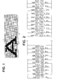
- FIG. 1 there is shown an exsample of a dot pattern character 1 output with the above-mentioned method.
- reference numeral 2 denotes dot matrices wherein dots 3 for defining dot pattern character 1 are located on intersections defined by logitudinal and lateral lines orthogonally intersecting with each other.
- the dot pattern character 1 is formed on the dot matrices 2.
- ther When expanding such a dot pattern character 1 and printing the expanded character or displaying it on a CRT (Cathode Ray Tube), ther has been generally used a method of enlarging the dot pattern so that its size is two times larger than that of the original pattern in a lateral direction by adding dots on respective dot locations of dot matrices defining an overall dot pattern.
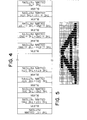
- Fig. 2 is an explanatory view illustrating an example of the above-mentioned image expanding method.
- This method includes the step of inputting a digital picture elements each pressed by a true binary digit and other picture elements each expressed by a false binary digit arranged in a series of columns, and applying a predetermined picture enlargement processing to the digital input picture with a part of the input picture or the whole thereof being as a unit of processing in a manner that the same picture element is repeated twice in a laterral direction.
- Fig. 3 shows an example of a dot pattern character configured by applying the above-mentioned character enlargement processing method to the dot pattern character shown in Fig. 1.
- an object of the present invention is to provide a picture enlargement processing system which is advantageous in that pictures or images to be formed are not destroyed or collapsed, a dot pattern has a uniform density, and a printing speed is not lowered.
- Another object of the present invention is to provide a dot-matrix printing apparatus configured by employing such a picture enlargement processing system.
- an enlarged picture output apparatus is characterized in that there are provided input means for inputting a picture pattern configured so that when there exists a dot at a picture element corresponding to each of intersections defined by columns and rows, the picture pattern is expressed by a true binary digit,while when there does not exist a dot thereat, the picture pattern is expressed by a false binary digit, and picture pattern enlargement converting means for applying an enlargement conversion processing to the picture pattern input from the input means as shown in Fig.
- a pattern of the first column of a picture pattern enlarged is configured by the same pattern as that of the first column of the input picture pattern
- each pattern of the 2n-th column (n is a positive integer more than 1) of the picture pattern enlarged is configured by a pattern expressed by the false binary digit alone
- each pattern of the (2n+1)-th column of the picture pattern enlarged is expressed by the true binary digit
- both picture elements corresponding to the n-th and (n+1)-th columns of the input picture pattern are expressed by the false binary digit
- each pattern of the (2n+1)-th column of the picture pattern enlarged is expressed by the false binary digit
- iv) a pattern of the final column of the picture pattern enlarged is configured by the same pattern as that of the final column of the input picture pattern
- character image obtained by applying an enlargement processing to the character pattern shown in Fig. 1 is formed in a manner that white patterns are inserted every second column of the character pattern defining an original picture, respectively shown in Fig.5, and therefore the contour of the enlarged character pattern cannot be destroyed in the form of stair-steps and the density of printing dots becomes uniform, thus enabling to obtain a character pattern clearly enlarged. Further,since dots do not appear in succession, there is no possibility that printing speed is not lowered even when staggered type dot pattern characters are expanded and the enlarged characters are printed.
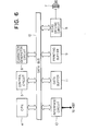
- Fig. 6 shows a block diagram of a processing apparatus used in an enbodiment of the invention.
- the processing apparatus comprises a CPU (Micro processor ) 4 (of the type 8085, Intel Corporation) in which an algorithm to be referred to later is stored and a predetermined processing is executed based thereon, a control circuit 5 for controlling the overall operation of the processing device under the supervision of the CPU 4, a chracter generator circuit 6 (of the type 2732, Intel Corporation) in which character patterns are stored, a printing head 7 of a wire dot system for printing characters, a head driving circuit 8 for driving the printing head 7, a printing buffer 9 (of the type TMS 4016, Texas Instruments Incorporated) for converting a dot pattern corresponding to a character code to head pins data, an interface circuit 10 of RS 232 C (ISO standard) for receiving data from an external device (not shown) such as a Host system etc. or transmitting it thereto, a data buffer 11 ( of the type TMS 4016NL, Texas Instruments Incorporated) for receiving data received from the external device through the interface circuit 10 and temporarily storing it therein, and
- the command is interpreted by the control circuit 5.
- a character pattern corresponding to the print character code is read out of the character generator circuit 6.
- the character pattern is configured in a manner that black picture elements, i.e. picture elements printed as dots with head pins are designated by a true binaly digit e.g. logical "1" and picture elements which are not printed i.e. picture elements expressed by a ground colour of a paper are designated by a false binary digit e.g. logical "1" in correspondence with matrices comprising columns and rows.
- the CPU 4 applies a predetermined enlargement processing to the character pattern thus read on the basis of an algorithm stored therein in accordance with a flowchart shown in Fig. 7 under the control of the control circuit 5.
- the character pattern is converted to data corresponding to head pins.
- the number of columns in the lateral direction of one character is n which is positive number more than 1 and the m-th dot column is being processed.
- the data of the first column is converted to data corresponding to head pin and the data thus converted is stored in the printing buffer 9 (step 2).
- blank data (which is not actually printed) is stored in the next column of the printing buffer 9 (step 3).
- step 4 the judgement is carried out as to whether the current data of the m-th column is in correspondence with the data of the n-th column, i.e. the final column thereof the lateral dot series of one character (step 4).
- data of the m-th column is not equal to the data of the final (n-th) column, i.e. in the case of m ⁇ n
- data of the next column of the (m+1)-th column is read out of the character generator 6 (step 5).
- a logical sum of data assigned to the m-th column of the character pattern defined by the input character data and data assigned to the (m+1)-th column same is performed.
- the data expressed by the logical sum thus performed is converted to data corresponding to head pins and then is stored in the printing buffer 9 (step 6).
- blank data is stored in the next vertical column of the printing buffer 9 (step 7).
- a printing command is fed from the control circuit 5 to the head drive circuit 9.
- the head drive circuit 8 allowing the printing head 7 to scan on a paper in one direction at a predetermined feeding speed, it drives a preselected pin of the printing head 7 in accordance with the data contents from the printing buffer 9 to print characters on the paper. Namely, when a signal corresponding to the true binary digit e.g. logical "1" is output, the head drive circuit 9 operates so as to drive head pin of a corresponding location, thereby to effect a printing.
- the present invention is applied to the enlargement of dot pattern character for printing.
- the present invention is not limited to such an embodiment. Namely, the present invention may be also applicable to the enlargement of characters which are displayed on a CRT, or printed with a printing device of a ink jet system for printing a picture in two colours different from each other in its density or gradation etc.
- the present invention is not limited to an enlargement processing for characters, and is applicable to a processing for enlarging a part or the whole of picture pattern of an image input from an external device via an input device.
- the present invention is applicable not only to an enlargement of pictures in a lateral direction but also to an enlargement thereof in a vertical direction.
Landscapes
- Physics & Mathematics (AREA)
- Engineering & Computer Science (AREA)
- Mathematical Physics (AREA)
- General Engineering & Computer Science (AREA)
- General Physics & Mathematics (AREA)
- Theoretical Computer Science (AREA)
- Editing Of Facsimile Originals (AREA)
- Controls And Circuits For Display Device (AREA)
- Dot-Matrix Printers And Others (AREA)
- Image Processing (AREA)
Applications Claiming Priority (2)
| Application Number | Priority Date | Filing Date | Title |
|---|---|---|---|
| JP59012452A JPS60155472A (ja) | 1984-01-26 | 1984-01-26 | 画像拡大処理方式 |
| JP12452/84 | 1984-01-26 |
Publications (2)
| Publication Number | Publication Date |
|---|---|
| EP0150988A2 true EP0150988A2 (de) | 1985-08-07 |
| EP0150988A3 EP0150988A3 (de) | 1985-08-21 |
Family
ID=11805727
Family Applications (1)
| Application Number | Title | Priority Date | Filing Date |
|---|---|---|---|
| EP85300465A Withdrawn EP0150988A3 (de) | 1984-01-26 | 1985-01-24 | Gerät zur Ausgabe von vergrösserten Bildern |
Country Status (4)
| Country | Link |
|---|---|
| EP (1) | EP0150988A3 (de) |
| JP (1) | JPS60155472A (de) |
| KR (1) | KR850005645A (de) |
| AU (1) | AU3775585A (de) |
Cited By (3)
| Publication number | Priority date | Publication date | Assignee | Title |
|---|---|---|---|---|
| EP0234018A3 (en) * | 1985-12-26 | 1989-03-29 | International Business Machines Corporation | Method and apparatus for converting the resolution of dot matrix display data |
| EP0331033A3 (de) * | 1988-02-29 | 1989-10-18 | Oki Electric Industry Company, Limited | Drucksystem für Punktmatrix-Drucker |
| GB2268380A (en) * | 1992-06-30 | 1994-01-05 | Fujitsu Ltd | Image processing system. |
Family Cites Families (2)
| Publication number | Priority date | Publication date | Assignee | Title |
|---|---|---|---|---|
| US3991868A (en) * | 1975-03-11 | 1976-11-16 | Centronics Data Computer Corporation | Method and apparatus for printing segmented characters |
| GB2012088B (en) * | 1978-01-09 | 1982-06-09 | Rank Organisation Ltd | Printer |
-
1984
- 1984-01-26 JP JP59012452A patent/JPS60155472A/ja active Pending
-
1985
- 1985-01-09 KR KR1019850000089A patent/KR850005645A/ko not_active Abandoned
- 1985-01-17 AU AU37755/85A patent/AU3775585A/en not_active Abandoned
- 1985-01-24 EP EP85300465A patent/EP0150988A3/de not_active Withdrawn
Cited By (5)
| Publication number | Priority date | Publication date | Assignee | Title |
|---|---|---|---|---|
| EP0234018A3 (en) * | 1985-12-26 | 1989-03-29 | International Business Machines Corporation | Method and apparatus for converting the resolution of dot matrix display data |
| EP0331033A3 (de) * | 1988-02-29 | 1989-10-18 | Oki Electric Industry Company, Limited | Drucksystem für Punktmatrix-Drucker |
| GB2268380A (en) * | 1992-06-30 | 1994-01-05 | Fujitsu Ltd | Image processing system. |
| GB2268380B (en) * | 1992-06-30 | 1996-05-15 | Fujitsu Ltd | Image processing system |
| US5557691A (en) * | 1992-06-30 | 1996-09-17 | Fujitsu Limited | Image processing system |
Also Published As
| Publication number | Publication date |
|---|---|
| KR850005645A (ko) | 1985-08-28 |
| JPS60155472A (ja) | 1985-08-15 |
| AU3775585A (en) | 1985-08-01 |
| EP0150988A3 (de) | 1985-08-21 |
Similar Documents
| Publication | Publication Date | Title |
|---|---|---|
| EP0211934B1 (de) | Elektronischer anzeiger | |
| EP0513989B1 (de) | Methode zur schnellen Punktvervielfachung für einen Rasterbilderzeuger und sich ergebende Datenstruktur für das Punktbild | |
| EP0115584B1 (de) | Bilderzeugungsapparat und Verarbeitungsverfahren für Bilddarstellungssignale zur Verwendung bei einem derartigen Apparat | |
| EP0422793B1 (de) | Graphische Skalierungsverfahren für hochauflösende Drucker | |
| US6582046B1 (en) | Method and device for image processing | |
| USRE36948E (en) | Print enhancement system for enhancing dot printer images | |
| EP0150988A2 (de) | Gerät zur Ausgabe von vergrösserten Bildern | |
| JP3490873B2 (ja) | 印刷装置 | |
| JP2539783B2 (ja) | インクジエツト印刷ヘツドの制御装置 | |
| EP0481621A2 (de) | Informationsverarbeitungsvorrichtung und -verfahren | |
| JP3055738B2 (ja) | ドットマトリクスパターンの印字方法および装置 | |
| US5876132A (en) | Method and system for high character density printing utilizing low pel density characters | |
| US5627652A (en) | Multibit RAM for parallel lookup of high resolution halftone screens | |
| JP2547716B2 (ja) | デ−タ処理システム | |
| JP3373345B2 (ja) | カラー表示装置 | |
| JP2715077B2 (ja) | 印刷装置 | |
| JP2657198B2 (ja) | ドットプリンタの印字方法 | |
| JP2801730B2 (ja) | データ圧縮方法 | |
| JPH082009A (ja) | シリアルプリンタ | |
| JPH03112671A (ja) | 印刷装置 | |
| JPH06238860A (ja) | 文字パターン発生方法 | |
| JPH05336355A (ja) | ドットマトリックスカラープリンター用制御信号生成方法及び同装置 | |
| JPH09214761A (ja) | 印刷装置 | |
| JPH0876739A (ja) | ビットマップフォントの縮小画面表示方法および縮小画面表示装置 | |
| JPS63286359A (ja) | パタ−ン発生方式 |
Legal Events
| Date | Code | Title | Description |
|---|---|---|---|
| PUAI | Public reference made under article 153(3) epc to a published international application that has entered the european phase |
Free format text: ORIGINAL CODE: 0009012 |
|
| PUAL | Search report despatched |
Free format text: ORIGINAL CODE: 0009013 |
|
| 17P | Request for examination filed |
Effective date: 19850206 |
|
| AK | Designated contracting states |
Designated state(s): DE FR GB NL |
|
| AK | Designated contracting states |
Designated state(s): DE FR GB NL |
|
| 17Q | First examination report despatched |
Effective date: 19870115 |
|
| STAA | Information on the status of an ep patent application or granted ep patent |
Free format text: STATUS: THE APPLICATION IS DEEMED TO BE WITHDRAWN |
|
| 18D | Application deemed to be withdrawn |
Effective date: 19870525 |
|
| RIN1 | Information on inventor provided before grant (corrected) |
Inventor name: MIYASHITA, KAZUHISA |