EP0151076A2 - Vorrichtung zur Verhinderung des Zutritts zu den Reifenleitern - Google Patents
Vorrichtung zur Verhinderung des Zutritts zu den Reifenleitern Download PDFInfo
- Publication number
- EP0151076A2 EP0151076A2 EP85400125A EP85400125A EP0151076A2 EP 0151076 A2 EP0151076 A2 EP 0151076A2 EP 85400125 A EP85400125 A EP 85400125A EP 85400125 A EP85400125 A EP 85400125A EP 0151076 A2 EP0151076 A2 EP 0151076A2
- Authority
- EP
- European Patent Office
- Prior art keywords
- panel
- ladder
- crinoline
- locking
- articulated
- Prior art date
- Legal status (The legal status is an assumption and is not a legal conclusion. Google has not performed a legal analysis and makes no representation as to the accuracy of the status listed.)
- Granted
Links
- 238000007789 sealing Methods 0.000 claims description 3
- 230000006835 compression Effects 0.000 description 2
- 238000007906 compression Methods 0.000 description 2
- 230000000694 effects Effects 0.000 description 2
- 230000036961 partial effect Effects 0.000 description 2
- 230000000717 retained effect Effects 0.000 description 2
- 230000009194 climbing Effects 0.000 description 1
- 238000010616 electrical installation Methods 0.000 description 1
- 238000009434 installation Methods 0.000 description 1
- 230000000670 limiting effect Effects 0.000 description 1
- 230000014759 maintenance of location Effects 0.000 description 1
- 230000001681 protective effect Effects 0.000 description 1
- 230000000284 resting effect Effects 0.000 description 1
Images


Classifications
-
- E—FIXED CONSTRUCTIONS
- E06—DOORS, WINDOWS, SHUTTERS, OR ROLLER BLINDS IN GENERAL; LADDERS
- E06C—LADDERS
- E06C9/00—Ladders characterised by being permanently attached to fixed structures, e.g. fire escapes
- E06C9/02—Ladders characterised by being permanently attached to fixed structures, e.g. fire escapes rigidly mounted
-
- E—FIXED CONSTRUCTIONS
- E06—DOORS, WINDOWS, SHUTTERS, OR ROLLER BLINDS IN GENERAL; LADDERS
- E06C—LADDERS
- E06C7/00—Component parts, supporting parts, or accessories
- E06C7/006—Devices for preventing access
-
- E—FIXED CONSTRUCTIONS
- E06—DOORS, WINDOWS, SHUTTERS, OR ROLLER BLINDS IN GENERAL; LADDERS
- E06C—LADDERS
- E06C7/00—Component parts, supporting parts, or accessories
- E06C7/18—Devices for preventing persons from falling
- E06C7/185—Devices providing a back support to a person on the ladder, e.g. cages
Definitions
- the subject of the invention is a device which is used to prohibit any unauthorized access to the crinoline ladders which exist in numerous industrial installations. These scales often lead to dangerous devices in operation, or necessary for safety, as found in electrical installations in the open air, in oil refineries, in important railway stations, etc ... It is therefore desirable that only authorized persons can use these ladders.
- the main purpose of the invention is to eliminate these drawbacks by providing a device for locking a crinoline ladder by preventing any access to the terminal part situated between the last bar of the crane and the last arch of the crinoline, in closing this last arch.
- Another object of the invention is to achieve a device of the type defined above which closes and which locks behind a person who borrows the ladder inside the crinoLine and which can be released easily. ment, without key, by the same person when she wants to get out of the crinoline and leave the ladder.
- the invention also aims to provide a teL device as defined above which, in addition, closes and locks automatically behind a person who takes the ladder inside the crinoline.
- a device comprises a panel pivoting around hinges fixed to an upright of the terminal part between the last bar of the ladder and the last arch of the crinoline; this panel is provided at its upper end with a closing disc which, in the closed position of the panel, prevents access to the interior of the crinoline.
- the panel is equipped with at least one locking means in the closed and unlocked position, this locking and unlocking means being provided on the one hand with an unlocking member accessible from the inside of the crinoline.
- a key lock accessible from the outside of the panel.
- the unlocking member can only be operated from inside the crinoline by any person on the ladder inside the crinoline when the panel is closed.
- the locking and unlocking means comprises a locking element pivotally mounted in its middle part around a horizontal axis carried by the upright of the ladder opposite the upright which carries the hinges of the panel and this element is articulated with a first bevel which extends to its articulation with an intermediate lever mounted pivoting in its middle part on the same amount of the scale at a level distant from that of the fixed shutter disc to the panel.
- This intermediate lever is provided with a stop finger which, in a first position of this lever, opposes the opening of the panel and which, in a second position of this lever, allows the opening of the sign.
- This intermediate lever is articulated opposite the first link, with respect to the horizontal axis, with a second link which extends upwards where it is articulated with an operating lever itself pivotally mounted in its middle part. on the same amount of the scale.
- the positions of the locking element and of the intermediate lever are opposed, so that the stop finger is in the position for retaining the closed panel when the locking element is in a position which does not allow the setting in place of the lock padlock.
- a person who borrows the ladder after having put the panel in the open position can pull the latter to its closed position and, using the operating lever, can immobilize the panel in its closed position by prohibiting Lock it from the outside using the locking element.
- the device comprises a means for automatically closing the panel consisting of any one of the following means: hinges offset relative to the vertical, spring hinges, return counterweight, etc. and the automatic locking means comprises a latch bolt lock or equivalent, of the snap-fastening type, this lock having an axis of operation of this bolt and a keyhole accessible from the outside by a key for operating said said bolt.
- the panel is hollow, at least partially, in its thickness, and it contains the unlocking means which comprises a rod mounted to slide against the action of a return means; at one end, this rod is functionally connected by an operating part to the pin operating axis; at its opposite end, this same rod is provided with a support element which is located on the panel and which is accessible from the interior of the crinoline when the panel is in the closed position.
- the unlocking means which comprises a rod mounted to slide against the action of a return means; at one end, this rod is functionally connected by an operating part to the pin operating axis; at its opposite end, this same rod is provided with a support element which is located on the panel and which is accessible from the interior of the crinoline when the panel is in the closed position.
- the support element is surrounded on three sides by a guard plate preventing it from being maneuvered from outside the crinoline.
- the shutter disc is articulated relative to the panel and foldable in the plane of the latter when the panel is in the open position.
- the shutter disc is foldable in the extension of the plane of the panel.
- the panel is hollow and iL contains a mechanism for operating the shutter disc.
- this mechanism comprises a rod articulated with the disc and articulated with a pusher which is applied against an amount of the scale.
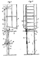
- This ladder 1 with two uprights 2,3 is provided with a crinoline 4, the lower arch 5 of which is at a distance above the floor of the order of 2,300 m.
- a panel 6 having the width of the ladder 1 is pivotally mounted by one of its longitudinal edges thanks to two hinges 7,8 fixed to the upright 3 at two points spaced vertically.
- the panel 6 extends at least between the last bar of the ladder and the last arch of the crinoline.
- the panel 6 is provided with a sealing disc 9 of dimension substantially equal to that of the lower arch 5 and capable of prohibiting access to the crinoline.
- a locking element 10 is pivotally mounted in its middle part around a horizontal axis 11. This element is drilled , in front of the panel 6 put in the closed position, a hole 12 to which then corresponds, in this same position of the panel, a hole drilled in correspondence in a locking tab 13 fixed to the panel 6. A padlock can then be engaged in the two holes to block the opening of the panel 6.
- the locking element 10 is articulated at 10A with a first link 14 which extends upwards above the closure disc 9.
- This link 14 is arranged in an oblique position, from the rear of the ladder 1 to the front of the latter where its free end 14A is articulated at 15 with one end of an intermediate lever diary 16 which is pivotally mounted in its middle part around a horizontal axis 17 carried by the same upright 2 of the ladder.
- the intermediate lever 16 When the locking element 10 is horizontal, the intermediate lever 16 is inclined relative to the horizontal with its articulation 15 located at the highest level. At its opposite end, beyond the axis 17, this intermediate lever 16 is articulated at 18 with a second link 19 which extends upwards parallel to the upright 2 of the ladder over a length of 1.50 m. approximately to be articulated at its free end, at 20, with an unlocking lever 21.
- This is pivotally mounted on the upright 2 of the ladder by means of a horizontal axis 22; iL extends inside the crinoline 4 so that it can be easily grasped and maneuvered; it always occupies a position in LaqueLLe it is parallel to the Intermediate lever 16.
- This intermediate lever 16 is provided, at a point situated between its pivot axis 17 and its articulation 15 with the first link 14, with a stop finger 23 directed downwards which can penetrate into a corresponding opening (not visible on The drawings) provided in the thickness of the panel 6, when the latter is in its closed position and when this intermediate lever 16 is placed in the horizontal position.
- the panel 6 In the protective position, the panel 6 is closed, the lower part of the ladder 1 and the entrance to the crinoLine 4 are inaccessible; the locking element 10 is horizontal (position where it is shown in solid line) and a padlock is closed in its hole 12 and in that of the tab 13.
- the intermediate lever 16 and the operating lever 21 are tilted upwards (position where they are represented in pLein line) and The stop finger 23 is not engaged in the corresponding opening provided in panel 6.
- the positions of the locking element 10 and the unlocking lever 21 are opposed, one allowing the worm rusting or Retention of the panel 6 in the closed position when the other does not allow it.
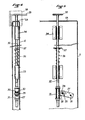
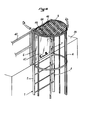
- FIGS. 3 to 5 where the parts identical or equivalent to those of the example of FIGS. 1,2 have been designated by the same references as on the latter.
- the locking means 10 comprises a closing element 24 fixed to the upright 2 having a keeper intended to receive a bolt of the half-turn type, with snap-fastening, of a lock 25 fixed in correspondence to the panel 6.
- This lock 25 has an operating pin 26 which makes it possible to maneuver the bolt, but this rod 26 is not accessible from the outside of the lock 25.
- a key which is introduced into the lock 25 used to maneuver the bolt from outside the panel 6.
- the panel 6 comprises two parallel walls which form between them in the thickness of the panel a volume where the operating pin 26 extends to be provided with an operating part 27- ( Figure 5).
- This has an end part 27A in which an elongated slot 28 is formed which is freely traversed by a pin 29.
- the latter is supported in the two branches 30 of a yoke 31 which contain between them the end part 27A of the operating part. 27.
- the yoke 31 is fixed to a sliding rod 32 which is guided in the thickness of the panel 6 by furnaces guide rails 33, 34 attached to one of the walls of this panel.
- the rod 32 extends upwards from the level of the lock 25 to above the upper edge 6A of the panel.
- the top of the rod 32 is provided above the panel 6 and the closure disc 9 with a support pedal 35.
- a compression spring 36 surrounds on a part of its length the sliding rod 32; it is supported on the one hand against the guide sleeve 33 and on the other hand against a pin 37 which passes through the rod 32. The latter is thus always recalled towards a higher position visible in FIGS. 3 to 5 on the bottom of the pedal 35 is at its highest level above the shutter disc 9 and the bolt is engaged in the keeper when the panel 6 is in the closed position.
- Panel 6 is mounted to automatically return to its closed position under the effect of a means known as a closing spring or counterweight or as a result of an offset position of the hinges.
- a means known as a closing spring or counterweight or as a result of an offset position of the hinges This automatic closing is also possible with the example of Figures 1 and 2.
- the bolt engages in the keeper of the closing element 24; no one can open panel 6 again without having the key. But, when this person descends the ladder, he just has to press with one foot on the pedal 35 to act via the sliding rod 32 on the operating pin 26 of the bolt and thus unlock and open the panel 6.
- the pedal 35 is surrounded on three sides by a guard plate 38 as indicated in phantom in Figure 4, so that it is inaccessible from the outside.
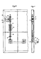
- Figures 6 to 9 relate to an exemplary embodiment of the device of the invention with a descending scale from a platform 39.
- the same references will be used as in the preceding figures to designate the identical or equivalent parts.
- SCALE 1 has two uprights 2,3 which are extended, without bars, above the level of platform 39;
- the extensions can be an integral part of the uprights 2,3 themselves, or be attached to the end of the latter, or even be part of a railing 40 (shown only partially) which borders the platform 39.
- the bars of the ladder stop roughly at the level of the platform 39 while that the last hoop of the crinoline 4 is located approximately at the level of the top of the railing 40.
- the panel 6 provided with the shutter disc 9 is mounted using spring hinges on the upright 3 in order to prohibit access to ladder 1 by closing the gap between the uprights 2,3 above the platform 39 substantially between the last bar of the ladder and the last hoop of the crinoline 4.
- the panel 6 has a lock (not shown) to which there corresponds a strike closure element, as in the example of FIGS. 3 to 5, so that this panel closes and locks automatically from its open position .
- the unlocking means is visible in detail in Figures 7,8. It comprises from the operating axis 26 of the lock The same parts 27 to 34 as those described above, except that the sliding rod 32 is shorter and does not extend outside the panel 6. At its lower end, opposite to that at which it is functionally connected to the lock, the sliding rod 32 is articulated by means of a link 41 (better visible in FIG. 7) with a tilting bar 42 which is located outside the panel 6.
- the tilting bar 42 is located at the bottom of the panel 6 to be accessible from the inside of the crinoLine when one reaches the top of the ladder 1.
- This bar 42 has two end transverse branches 43 which partially penetrate inside the panel 6 to be articulated around an axis 44 supported by a bearing 45.
- the tilting bar 42 which is articulated relative to the panel 6 constitutes the support element formed in the example of FIGS. 3 to 5 by the pedal 35.
- This bar 42 could also be surrounded on three sides by a guard plate preventing any access from outside the crinoline.
- the movements of the panel 6 can be imposed manually on it and immobilization means at its two extreme positions can be provided.
- an operating mechanism housed in the thickness of the panel 6 and capable of automatically moving the shutter disc 9 between a first position where this disc is perpendicular to the panel 6 (as in FIG. 6) and a second position where iL is raised in the extension of panel 6, roughly in the same plane as the latter.
- the shutter disc 9 is provided on its side fixed to the hinges 46 with a yoke 47, preferably located at a central position between the hinges 46.
- This yoke 47 is used for articulation around an axis 48 of a rod 49 which extends downwards in the thickness of panel 6 where it is guided in sliding by a guide 50; this rod 49 ends, substantially in the middle of the panel 6, by a stirrup 51 which contains between its branches a pusher 52.
- the latter has a semi-circular profile; It is articulated at two points which are diametrically opposite on the one hand with the stirrup 51 by an axis 53, on the other hand with the panel 6 by means of an axis 54.
- the latter is mounted to slide freely in a slot 55, not parallel to rod 49, preferably perpendicular to the latter.
- This slot 55 is formed in a U-shaped guide part 56 which forms part of the panel 6.
- the pusher 52 is likely to be partially projecting outside the panel 6, by a LongitudinaLe slice thereof which has a corresponding opening, on the side where the hinges 7 for mounting this panel 6 on the upright 3, as indicated in phantom in Figure 10.
- the axis 54 is at the outer end of the slot 55;
- the stirrup 51 and the axis 53 are then in their lower position, indicated in phantom, and the shutter disc 9 is erected, as indicated also in phantom in FIG. 9.
- This situation can be obtained thanks to a compression spring 57 which surrounds the rod 49 and which rests on the one hand against the fixed guide 50, on the other hand against a washer 58 retained in position on the rod 49 by a screwed nut 59.
- This spring 57 provides at least part of the force required to lift the shutter disc 9 and hold it in the upright position.
- This mechanism for operating the closing disc is mounted in the thickness of the panel 6 in addition to the unlocking means described above.
Landscapes
- Engineering & Computer Science (AREA)
- Mechanical Engineering (AREA)
- Ladders (AREA)
- Programmable Controllers (AREA)
Priority Applications (1)
| Application Number | Priority Date | Filing Date | Title |
|---|---|---|---|
| AT85400125T ATE36890T1 (de) | 1984-01-27 | 1985-01-25 | Vorrichtung zur verhinderung des zutritts zu den reifenleitern. |
Applications Claiming Priority (2)
| Application Number | Priority Date | Filing Date | Title |
|---|---|---|---|
| FR8401286A FR2558890B1 (fr) | 1984-01-27 | 1984-01-27 | Dispositif pour condamner l'acces aux echelles a crinoline |
| FR8401286 | 1984-01-27 |
Publications (3)
| Publication Number | Publication Date |
|---|---|
| EP0151076A2 true EP0151076A2 (de) | 1985-08-07 |
| EP0151076A3 EP0151076A3 (en) | 1987-01-14 |
| EP0151076B1 EP0151076B1 (de) | 1988-08-31 |
Family
ID=9300530
Family Applications (1)
| Application Number | Title | Priority Date | Filing Date |
|---|---|---|---|
| EP85400125A Expired EP0151076B1 (de) | 1984-01-27 | 1985-01-25 | Vorrichtung zur Verhinderung des Zutritts zu den Reifenleitern |
Country Status (5)
| Country | Link |
|---|---|
| US (1) | US4664225A (de) |
| EP (1) | EP0151076B1 (de) |
| AT (1) | ATE36890T1 (de) |
| DE (2) | DE3564719D1 (de) |
| FR (1) | FR2558890B1 (de) |
Cited By (12)
| Publication number | Priority date | Publication date | Assignee | Title |
|---|---|---|---|---|
| DE8804398U1 (de) * | 1988-03-31 | 1988-05-11 | Soell Industrieschmiede Gmbh, 8670 Hof | Vorrichtung zum Verhindern des Besteigens von Leitern durch Unbefugte |
| EP0314565A1 (de) * | 1987-10-30 | 1989-05-03 | Coutier Industrie | Vorrichtung zum Verschliessen des oberen Zugangs eines senkrechten rohrförmigen Schachtes |
| WO1989011312A1 (en) * | 1988-05-24 | 1989-11-30 | Histi Development As | Emergency stairs for external mounting on buildings |
| FR2635357A1 (fr) * | 1988-08-09 | 1990-02-16 | Coutier Ind | Dispositif de condamnation de l'acces inferieur d'une echelle |
| FR2636360A1 (fr) * | 1988-09-09 | 1990-03-16 | Coutier Ind | Panneau d'obturation pivotant equipe d'un dispositif de verrouillage |
| FR2647830A1 (fr) * | 1989-06-05 | 1990-12-07 | Coutier Ind | Dispositif de sectionnement d'un passage vertical equipe d'une echelle |
| EP0402214A1 (de) * | 1989-06-05 | 1990-12-12 | Etablissements Charles Coutier | Steigschutzvorrichtung zu einer Leiter von einem darüberliegenden Fussboden |
| FR2650623A1 (fr) * | 1989-08-04 | 1991-02-08 | Coutier Ind | Echelle a dispositif anti-chute et a condamnation d'acces |
| WO1995001495A1 (de) * | 1993-07-02 | 1995-01-12 | Söll Gmbh | Ruhepodest |
| FR2728012A1 (fr) * | 1994-12-08 | 1996-06-14 | Mcmi | Dispositif pour limiter l'acces inferieur a une echelle a crinoline |
| FR2799501A1 (fr) | 1999-10-07 | 2001-04-13 | Securite Signalisation | Dispositif pour condamner l'acces inferieur d'une telle echelle a crinoline |
| FR2817902A1 (fr) * | 2000-12-07 | 2002-06-14 | Coutier Ind | Dispositif de condamnation securisee de l'acces a une echelle a crinoline |
Families Citing this family (16)
| Publication number | Priority date | Publication date | Assignee | Title |
|---|---|---|---|---|
| US4991691A (en) * | 1990-06-22 | 1991-02-12 | Brawer David B | Stair barrier |
| US5080192A (en) * | 1990-12-05 | 1992-01-14 | Material Control, Inc. | Ladder with warning gate |
| US5255758A (en) * | 1991-02-25 | 1993-10-26 | Cherokee Construction Co. | Protective ladder assembly for scaffolding structure |
| US5343977A (en) * | 1992-05-19 | 1994-09-06 | Bryan Robin R | Ladder shield |
| USD347917S (en) | 1993-05-14 | 1994-06-14 | Bedsole Robert D | Worker lift platform |
| GB2353557A (en) * | 1999-04-30 | 2001-02-28 | James Stuart Austin | Trench safety cover |
| US7137478B2 (en) * | 2004-02-27 | 2006-11-21 | Brand Services, Inc. | Ladder safety cage |
| US20070151801A1 (en) * | 2005-12-30 | 2007-07-05 | Starcon International, Inc. | Collapsible ladder cage |
| DE202008009282U1 (de) * | 2008-07-10 | 2009-11-12 | Daas, Kamal | Gittertragwerk mit Evakuierungsmitteln |
| US8720644B2 (en) | 2011-08-03 | 2014-05-13 | Tony Floyd Naranjo | Aboveground pool child ladder safeguard device |
| US8584409B1 (en) | 2012-10-01 | 2013-11-19 | Victor Hibbard | Stairway barricade assemblies and methods |
| US9233647B1 (en) * | 2015-06-26 | 2016-01-12 | Dejana Truck & Utility | Shelving system with a ladder cage |
| GB201603410D0 (en) * | 2016-02-26 | 2016-04-13 | Bakkavör Ltd | Locking apparatus |
| US11692395B1 (en) * | 2020-02-25 | 2023-07-04 | Robert Wade Bullock | Ladder blocking device |
| US12404722B2 (en) * | 2022-04-14 | 2025-09-02 | Mirza Faizan | Method and system for providing a smart ladder to a user |
| KR102772237B1 (ko) * | 2023-11-09 | 2025-02-25 | 주식회사 흥진캐노피 | 안전 사다리용 출입통제장치 |
Family Cites Families (8)
| Publication number | Priority date | Publication date | Assignee | Title |
|---|---|---|---|---|
| DE55011C (de) * | R. GOTTSCHALK in Chemnitz i. S | Rettungsleiter zur Benutzung bei Feuersgefahr | ||
| US2535544A (en) * | 1948-01-09 | 1950-12-26 | William D Mckinley | Safety ladder |
| US3044572A (en) * | 1959-09-25 | 1962-07-17 | William A Da Lee Inc | Retractable safety landing for an access tube |
| US3038555A (en) * | 1960-02-18 | 1962-06-12 | William A Da Lee Inc | Retractable safety landing for an access tube |
| US3225863A (en) * | 1964-06-04 | 1965-12-28 | Howard T Ludlow | Safety ladder |
| SU431291A1 (ru) * | 1972-12-19 | 1974-06-05 | В. И. Башков , В. Г. Сонин | Лестница |
| US3968857A (en) * | 1975-02-20 | 1976-07-13 | Bryan Robin R | Device for preventing unauthorized access to permanent ladders |
| US4524848A (en) * | 1984-07-16 | 1985-06-25 | Russo John B | Device for deterring unauthorized climbing of permanent ladders |
-
1984
- 1984-01-27 FR FR8401286A patent/FR2558890B1/fr not_active Expired
-
1985
- 1985-01-25 EP EP85400125A patent/EP0151076B1/de not_active Expired
- 1985-01-25 DE DE8585400125T patent/DE3564719D1/de not_active Expired
- 1985-01-25 DE DE198585400125T patent/DE151076T1/de active Pending
- 1985-01-25 AT AT85400125T patent/ATE36890T1/de not_active IP Right Cessation
-
1986
- 1986-07-07 US US06/882,504 patent/US4664225A/en not_active Expired - Lifetime
Cited By (17)
| Publication number | Priority date | Publication date | Assignee | Title |
|---|---|---|---|---|
| EP0314565A1 (de) * | 1987-10-30 | 1989-05-03 | Coutier Industrie | Vorrichtung zum Verschliessen des oberen Zugangs eines senkrechten rohrförmigen Schachtes |
| FR2622631A1 (de) * | 1987-10-30 | 1989-05-05 | Coutier Ind | |
| DE8804398U1 (de) * | 1988-03-31 | 1988-05-11 | Soell Industrieschmiede Gmbh, 8670 Hof | Vorrichtung zum Verhindern des Besteigens von Leitern durch Unbefugte |
| US5131493A (en) * | 1988-05-24 | 1992-07-21 | Histi Development As | Emergency stairs for external mounting on buildings |
| WO1989011312A1 (en) * | 1988-05-24 | 1989-11-30 | Histi Development As | Emergency stairs for external mounting on buildings |
| FR2635357A1 (fr) * | 1988-08-09 | 1990-02-16 | Coutier Ind | Dispositif de condamnation de l'acces inferieur d'une echelle |
| WO1990002863A1 (fr) * | 1988-09-09 | 1990-03-22 | Coutier Industrie | Panneau d'obturation pivotant equipe d'un dispositif de verrouillage |
| FR2636360A1 (fr) * | 1988-09-09 | 1990-03-16 | Coutier Ind | Panneau d'obturation pivotant equipe d'un dispositif de verrouillage |
| FR2647830A1 (fr) * | 1989-06-05 | 1990-12-07 | Coutier Ind | Dispositif de sectionnement d'un passage vertical equipe d'une echelle |
| EP0402214A1 (de) * | 1989-06-05 | 1990-12-12 | Etablissements Charles Coutier | Steigschutzvorrichtung zu einer Leiter von einem darüberliegenden Fussboden |
| WO1990015219A1 (fr) * | 1989-06-05 | 1990-12-13 | Coutier Industrie | Dispositif de protection de l'acces a une echelle a partir d'un plancher superieur |
| FR2650623A1 (fr) * | 1989-08-04 | 1991-02-08 | Coutier Ind | Echelle a dispositif anti-chute et a condamnation d'acces |
| WO1991002136A1 (fr) * | 1989-08-04 | 1991-02-21 | Coutier Industrie | Echelle a dispositif anti-chute et a condamnation d'acces |
| WO1995001495A1 (de) * | 1993-07-02 | 1995-01-12 | Söll Gmbh | Ruhepodest |
| FR2728012A1 (fr) * | 1994-12-08 | 1996-06-14 | Mcmi | Dispositif pour limiter l'acces inferieur a une echelle a crinoline |
| FR2799501A1 (fr) | 1999-10-07 | 2001-04-13 | Securite Signalisation | Dispositif pour condamner l'acces inferieur d'une telle echelle a crinoline |
| FR2817902A1 (fr) * | 2000-12-07 | 2002-06-14 | Coutier Ind | Dispositif de condamnation securisee de l'acces a une echelle a crinoline |
Also Published As
| Publication number | Publication date |
|---|---|
| EP0151076A3 (en) | 1987-01-14 |
| ATE36890T1 (de) | 1988-09-15 |
| FR2558890B1 (fr) | 1986-06-20 |
| DE3564719D1 (en) | 1988-10-06 |
| DE151076T1 (de) | 1986-01-16 |
| US4664225A (en) | 1987-05-12 |
| EP0151076B1 (de) | 1988-08-31 |
| FR2558890A1 (fr) | 1985-08-02 |
Similar Documents
| Publication | Publication Date | Title |
|---|---|---|
| EP0151076B1 (de) | Vorrichtung zur Verhinderung des Zutritts zu den Reifenleitern | |
| WO2022069173A1 (fr) | Dispositif de gestion de l'acces et d'usage d'une echelle | |
| EP4183972B1 (de) | Zugangsverriegelungsvorrichtung | |
| WO2008110696A1 (fr) | Dispositif de protection pour un ascenseur et ascenseur comportant un tel dispositif | |
| EP0314565B1 (de) | Vorrichtung zum Verschliessen des oberen Zugangs eines senkrechten rohrförmigen Schachtes | |
| FR2635357A1 (fr) | Dispositif de condamnation de l'acces inferieur d'une echelle | |
| EP0485489B1 (de) | Leiter mit fallschutzvorrichtung und besteigungsverhinderung | |
| EP0802143B1 (de) | Mechanische Sicherheitsvorrichtung für den Benutzer eines Aufzuges zwischen zwei Stockwerken | |
| CA1266636A (fr) | Dispositif pour condamner l'acces aux echelles | |
| EP0161960B1 (de) | Einrichtung für die Aufbewahrung von Einkaufswagen | |
| FR2636360A1 (fr) | Panneau d'obturation pivotant equipe d'un dispositif de verrouillage | |
| EP0898916B1 (de) | Zentralverschluss für eine Briefkastenanlage | |
| EP0402214B1 (de) | Steigschutzvorrichtung zu einer Leiter von einem darüberliegenden Fussboden | |
| EP0863292A1 (de) | Sperrvorrichtung für Bereiche mit Zugangskontrolle | |
| FR2728012A1 (fr) | Dispositif pour limiter l'acces inferieur a une echelle a crinoline | |
| EP0771718B1 (de) | Fahrzeugaufbau, bestehend aus einem Unterbau, einem Oberbau und mindestens einer Schiebetür und zwei Flügeltüren | |
| FR2980512A1 (fr) | Barriere-ecluse pivotante pour passerelle | |
| FR2817902A1 (fr) | Dispositif de condamnation securisee de l'acces a une echelle a crinoline | |
| FR2725971A1 (fr) | Dispositif d'acces au fonds de cuvette des ascenseurs | |
| FR3140901A1 (fr) | Dispositif de gestion d’usage d’une échelle | |
| FR2647830A1 (fr) | Dispositif de sectionnement d'un passage vertical equipe d'une echelle | |
| FR2777929A1 (fr) | Plate-forme telescopique | |
| FR2872197A1 (fr) | Agencement de securite avec un portillon d'acces, notamment au bassin d'une piscine | |
| FR2654125A1 (fr) | Borne de stationnement rabattable. | |
| FR2780076A1 (fr) | Systeme de verrouillage d'une barriere de limitation d'acces a des voies reservees et barriere munie d'un tel systeme |
Legal Events
| Date | Code | Title | Description |
|---|---|---|---|
| PUAI | Public reference made under article 153(3) epc to a published international application that has entered the european phase |
Free format text: ORIGINAL CODE: 0009012 |
|
| 17P | Request for examination filed |
Effective date: 19850129 |
|
| AK | Designated contracting states |
Kind code of ref document: A2 Designated state(s): AT BE CH DE FR GB IT LI LU NL SE Designated state(s): AT BE CH DE FR GB IT LI LU NL SE |
|
| DET | De: translation of patent claims | ||
| PUAL | Search report despatched |
Free format text: ORIGINAL CODE: 0009013 |
|
| AK | Designated contracting states |
Kind code of ref document: A3 Designated state(s): AT BE CH DE FR GB IT LI LU NL SE |
|
| 17Q | First examination report despatched |
Effective date: 19880212 |
|
| ITF | It: translation for a ep patent filed | ||
| GRAA | (expected) grant |
Free format text: ORIGINAL CODE: 0009210 |
|
| AK | Designated contracting states |
Kind code of ref document: B1 Designated state(s): AT BE CH DE FR GB IT LI LU NL SE |
|
| REF | Corresponds to: |
Ref document number: 36890 Country of ref document: AT Date of ref document: 19880915 Kind code of ref document: T |
|
| GBT | Gb: translation of ep patent filed (gb section 77(6)(a)/1977) | ||
| REF | Corresponds to: |
Ref document number: 3564719 Country of ref document: DE Date of ref document: 19881006 |
|
| PLBE | No opposition filed within time limit |
Free format text: ORIGINAL CODE: 0009261 |
|
| STAA | Information on the status of an ep patent application or granted ep patent |
Free format text: STATUS: NO OPPOSITION FILED WITHIN TIME LIMIT |
|
| 26N | No opposition filed | ||
| ITTA | It: last paid annual fee | ||
| REG | Reference to a national code |
Ref country code: FR Ref legal event code: CL |
|
| EPTA | Lu: last paid annual fee | ||
| EAL | Se: european patent in force in sweden |
Ref document number: 85400125.2 |
|
| REG | Reference to a national code |
Ref country code: GB Ref legal event code: IF02 |
|
| PGFP | Annual fee paid to national office [announced via postgrant information from national office to epo] |
Ref country code: SE Payment date: 20030117 Year of fee payment: 19 |
|
| PGFP | Annual fee paid to national office [announced via postgrant information from national office to epo] |
Ref country code: LU Payment date: 20030122 Year of fee payment: 19 Ref country code: GB Payment date: 20030122 Year of fee payment: 19 |
|
| PGFP | Annual fee paid to national office [announced via postgrant information from national office to epo] |
Ref country code: AT Payment date: 20030123 Year of fee payment: 19 |
|
| PGFP | Annual fee paid to national office [announced via postgrant information from national office to epo] |
Ref country code: DE Payment date: 20030129 Year of fee payment: 19 |
|
| PGFP | Annual fee paid to national office [announced via postgrant information from national office to epo] |
Ref country code: NL Payment date: 20030130 Year of fee payment: 19 Ref country code: CH Payment date: 20030130 Year of fee payment: 19 |
|
| PGFP | Annual fee paid to national office [announced via postgrant information from national office to epo] |
Ref country code: BE Payment date: 20030204 Year of fee payment: 19 |
|
| PG25 | Lapsed in a contracting state [announced via postgrant information from national office to epo] |
Ref country code: LU Free format text: LAPSE BECAUSE OF NON-PAYMENT OF DUE FEES Effective date: 20040125 Ref country code: GB Free format text: LAPSE BECAUSE OF NON-PAYMENT OF DUE FEES Effective date: 20040125 Ref country code: AT Free format text: LAPSE BECAUSE OF NON-PAYMENT OF DUE FEES Effective date: 20040125 |
|
| PG25 | Lapsed in a contracting state [announced via postgrant information from national office to epo] |
Ref country code: SE Free format text: LAPSE BECAUSE OF NON-PAYMENT OF DUE FEES Effective date: 20040126 |
|
| PGFP | Annual fee paid to national office [announced via postgrant information from national office to epo] |
Ref country code: FR Payment date: 20040127 Year of fee payment: 20 |
|
| PG25 | Lapsed in a contracting state [announced via postgrant information from national office to epo] |
Ref country code: LI Free format text: LAPSE BECAUSE OF NON-PAYMENT OF DUE FEES Effective date: 20040131 Ref country code: CH Free format text: LAPSE BECAUSE OF NON-PAYMENT OF DUE FEES Effective date: 20040131 Ref country code: BE Free format text: LAPSE BECAUSE OF NON-PAYMENT OF DUE FEES Effective date: 20040131 |
|
| BERE | Be: lapsed |
Owner name: ETS CHARLES *COUTIER Effective date: 20040131 |
|
| PG25 | Lapsed in a contracting state [announced via postgrant information from national office to epo] |
Ref country code: NL Free format text: LAPSE BECAUSE OF NON-PAYMENT OF DUE FEES Effective date: 20040801 |
|
| PG25 | Lapsed in a contracting state [announced via postgrant information from national office to epo] |
Ref country code: DE Free format text: LAPSE BECAUSE OF NON-PAYMENT OF DUE FEES Effective date: 20040803 |
|
| EUG | Se: european patent has lapsed | ||
| GBPC | Gb: european patent ceased through non-payment of renewal fee |
Effective date: 20040125 |
|
| REG | Reference to a national code |
Ref country code: CH Ref legal event code: PL |
|
| NLV4 | Nl: lapsed or anulled due to non-payment of the annual fee |
Effective date: 20040801 |