EP0151200A1 - Vorrichtung zum Speisen eines Rohmaterials - Google Patents
Vorrichtung zum Speisen eines Rohmaterials Download PDFInfo
- Publication number
- EP0151200A1 EP0151200A1 EP19840101237 EP84101237A EP0151200A1 EP 0151200 A1 EP0151200 A1 EP 0151200A1 EP 19840101237 EP19840101237 EP 19840101237 EP 84101237 A EP84101237 A EP 84101237A EP 0151200 A1 EP0151200 A1 EP 0151200A1
- Authority
- EP
- European Patent Office
- Prior art keywords
- raw material
- material container
- liquid
- container
- pipe
- Prior art date
- Legal status (The legal status is an assumption and is not a legal conclusion. Google has not performed a legal analysis and makes no representation as to the accuracy of the status listed.)
- Granted
Links
Images
Classifications
-
- C—CHEMISTRY; METALLURGY
- C03—GLASS; MINERAL OR SLAG WOOL
- C03B—MANUFACTURE, SHAPING, OR SUPPLEMENTARY PROCESSES
- C03B37/00—Manufacture or treatment of flakes, fibres, or filaments from softened glass, minerals, or slags
- C03B37/01—Manufacture of glass fibres or filaments
- C03B37/012—Manufacture of preforms for drawing fibres or filaments
- C03B37/014—Manufacture of preforms for drawing fibres or filaments made entirely or partially by chemical means, e.g. vapour phase deposition of bulk porous glass either by outside vapour deposition [OVD], or by outside vapour phase oxidation [OVPO] or by vapour axial deposition [VAD]
- C03B37/01413—Reactant delivery systems
-
- B—PERFORMING OPERATIONS; TRANSPORTING
- B01—PHYSICAL OR CHEMICAL PROCESSES OR APPARATUS IN GENERAL
- B01J—CHEMICAL OR PHYSICAL PROCESSES, e.g. CATALYSIS OR COLLOID CHEMISTRY; THEIR RELEVANT APPARATUS
- B01J4/00—Feed or outlet devices; Feed or outlet control devices
- B01J4/008—Feed or outlet control devices
-
- C—CHEMISTRY; METALLURGY
- C03—GLASS; MINERAL OR SLAG WOOL
- C03C—CHEMICAL COMPOSITION OF GLASSES, GLAZES OR VITREOUS ENAMELS; SURFACE TREATMENT OF GLASS; SURFACE TREATMENT OF FIBRES OR FILAMENTS MADE FROM GLASS, MINERALS OR SLAGS; JOINING GLASS TO GLASS OR OTHER MATERIALS
- C03C17/00—Surface treatment of glass, not in the form of fibres or filaments, by coating
- C03C17/02—Surface treatment of glass, not in the form of fibres or filaments, by coating with glass
-
- C—CHEMISTRY; METALLURGY
- C23—COATING METALLIC MATERIAL; COATING MATERIAL WITH METALLIC MATERIAL; CHEMICAL SURFACE TREATMENT; DIFFUSION TREATMENT OF METALLIC MATERIAL; COATING BY VACUUM EVAPORATION, BY SPUTTERING, BY ION IMPLANTATION OR BY CHEMICAL VAPOUR DEPOSITION, IN GENERAL; INHIBITING CORROSION OF METALLIC MATERIAL OR INCRUSTATION IN GENERAL
- C23C—COATING METALLIC MATERIAL; COATING MATERIAL WITH METALLIC MATERIAL; SURFACE TREATMENT OF METALLIC MATERIAL BY DIFFUSION INTO THE SURFACE, BY CHEMICAL CONVERSION OR SUBSTITUTION; COATING BY VACUUM EVAPORATION, BY SPUTTERING, BY ION IMPLANTATION OR BY CHEMICAL VAPOUR DEPOSITION, IN GENERAL
- C23C16/00—Chemical coating by decomposition of gaseous compounds, without leaving reaction products of surface material in the coating, i.e. chemical vapour deposition [CVD] processes
- C23C16/44—Chemical coating by decomposition of gaseous compounds, without leaving reaction products of surface material in the coating, i.e. chemical vapour deposition [CVD] processes characterised by the method of coating
- C23C16/448—Chemical coating by decomposition of gaseous compounds, without leaving reaction products of surface material in the coating, i.e. chemical vapour deposition [CVD] processes characterised by the method of coating characterised by the method used for generating reactive gas streams, e.g. by evaporation or sublimation of precursor materials
- C23C16/4481—Chemical coating by decomposition of gaseous compounds, without leaving reaction products of surface material in the coating, i.e. chemical vapour deposition [CVD] processes characterised by the method of coating characterised by the method used for generating reactive gas streams, e.g. by evaporation or sublimation of precursor materials by evaporation using carrier gas in contact with the source material
- C23C16/4482—Chemical coating by decomposition of gaseous compounds, without leaving reaction products of surface material in the coating, i.e. chemical vapour deposition [CVD] processes characterised by the method of coating characterised by the method used for generating reactive gas streams, e.g. by evaporation or sublimation of precursor materials by evaporation using carrier gas in contact with the source material by bubbling of carrier gas through liquid source material
-
- G—PHYSICS
- G05—CONTROLLING; REGULATING
- G05D—SYSTEMS FOR CONTROLLING OR REGULATING NON-ELECTRIC VARIABLES
- G05D7/00—Control of flow
-
- G—PHYSICS
- G05—CONTROLLING; REGULATING
- G05D—SYSTEMS FOR CONTROLLING OR REGULATING NON-ELECTRIC VARIABLES
- G05D9/00—Level control, e.g. controlling quantity of material stored in vessel
- G05D9/12—Level control, e.g. controlling quantity of material stored in vessel characterised by the use of electric means
-
- C—CHEMISTRY; METALLURGY
- C03—GLASS; MINERAL OR SLAG WOOL
- C03B—MANUFACTURE, SHAPING, OR SUPPLEMENTARY PROCESSES
- C03B2207/00—Glass deposition burners
- C03B2207/80—Feeding the burner or the burner-heated deposition site
- C03B2207/81—Constructional details of the feed line, e.g. heating, insulation, material, manifolds, filters
-
- C—CHEMISTRY; METALLURGY
- C03—GLASS; MINERAL OR SLAG WOOL
- C03B—MANUFACTURE, SHAPING, OR SUPPLEMENTARY PROCESSES
- C03B2207/00—Glass deposition burners
- C03B2207/80—Feeding the burner or the burner-heated deposition site
- C03B2207/85—Feeding the burner or the burner-heated deposition site with vapour generated from liquid glass precursors, e.g. directly by heating the liquid
- C03B2207/86—Feeding the burner or the burner-heated deposition site with vapour generated from liquid glass precursors, e.g. directly by heating the liquid by bubbling a gas through the liquid
-
- C—CHEMISTRY; METALLURGY
- C03—GLASS; MINERAL OR SLAG WOOL
- C03B—MANUFACTURE, SHAPING, OR SUPPLEMENTARY PROCESSES
- C03B2207/00—Glass deposition burners
- C03B2207/80—Feeding the burner or the burner-heated deposition site
- C03B2207/85—Feeding the burner or the burner-heated deposition site with vapour generated from liquid glass precursors, e.g. directly by heating the liquid
- C03B2207/89—Controlling the liquid level in or supply to the tank
-
- C—CHEMISTRY; METALLURGY
- C03—GLASS; MINERAL OR SLAG WOOL
- C03B—MANUFACTURE, SHAPING, OR SUPPLEMENTARY PROCESSES
- C03B2207/00—Glass deposition burners
- C03B2207/80—Feeding the burner or the burner-heated deposition site
- C03B2207/90—Feeding the burner or the burner-heated deposition site with vapour generated from solid glass precursors, i.e. by sublimation
-
- Y—GENERAL TAGGING OF NEW TECHNOLOGICAL DEVELOPMENTS; GENERAL TAGGING OF CROSS-SECTIONAL TECHNOLOGIES SPANNING OVER SEVERAL SECTIONS OF THE IPC; TECHNICAL SUBJECTS COVERED BY FORMER USPC CROSS-REFERENCE ART COLLECTIONS [XRACs] AND DIGESTS
- Y10—TECHNICAL SUBJECTS COVERED BY FORMER USPC
- Y10T—TECHNICAL SUBJECTS COVERED BY FORMER US CLASSIFICATION
- Y10T137/00—Fluid handling
- Y10T137/2931—Diverse fluid containing pressure systems
- Y10T137/3115—Gas pressure storage over or displacement of liquid
- Y10T137/3127—With gas maintenance or application
-
- Y—GENERAL TAGGING OF NEW TECHNOLOGICAL DEVELOPMENTS; GENERAL TAGGING OF CROSS-SECTIONAL TECHNOLOGIES SPANNING OVER SEVERAL SECTIONS OF THE IPC; TECHNICAL SUBJECTS COVERED BY FORMER USPC CROSS-REFERENCE ART COLLECTIONS [XRACs] AND DIGESTS
- Y10—TECHNICAL SUBJECTS COVERED BY FORMER USPC
- Y10T—TECHNICAL SUBJECTS COVERED BY FORMER US CLASSIFICATION
- Y10T137/00—Fluid handling
- Y10T137/2931—Diverse fluid containing pressure systems
- Y10T137/3115—Gas pressure storage over or displacement of liquid
- Y10T137/3127—With gas maintenance or application
- Y10T137/313—Gas carried by or evolved from liquid
- Y10T137/3133—Gas injectors
Definitions
- the present invention relates to a raw material supply device for supplying a gaseous glass raw material (frit) to a reaction device of producing a preform (mother material) used in the production of an optical fiber.
- a MCVD method for producing a preform for optical fiber of a type used for communication
- a VAD method and 'like methods have been employed. Such methods are described in "Techniques of Optical Fiber for Communication on Survey of The Patent Journal" (compiled by the Japanese Patent Office, published by The Invention Association of Japan) April 20, 1982, pp. 89-122.
- a supply of a liquid glass raw material (frit) of which silicon tetracloride serves as the main raw material and including germanium tetracloride or the like as a dopant is. put into a raw material container.
- a carrier gas is introduced which evaporates the raw material.
- the carrier gas including the gaseous raw material in the saturated or nearly saturated state is applied to a reaction device for production of the preform.
- the gas is oxidized, resulting in an accumulation of a grained oxide product, namely, the preform.
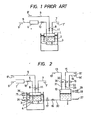
- a conventional raw material supply device for implementing the above process was constructed as shown in Fig. 1.
- a liquid glass raw material 2 is charged in a raw material container 1 and this container, in turn, is received in a temperature-controlled bath 3 employed to maintain the temperature of the material container and its contents uniform.
- the raw material container 1 is secured to the bottom of the temperature-controlled bath 3 directly or indirectly via supporting stands 4.
- a carrier gas 5 1 is introduced into the raw material container 1 through a pipe 5 and a flow control device 6 (such as a mass flowmeter).
- the carrier gas 5' which is supplied in a bubbling state, absorbs the raw material gas, becoming saturated or nearly saturated therewith.
- the gas which is now a reacting gas 7 1 , is passed from the raw material container 1 through a pipe 7 to a reaction device (not shown).
- the carrier gas need not necessarily be supplied in the bubbling state. It is possible merely to introduce the gas into a space above the liquid level and cause the same to be mixed with the raw material gas evaporated from the liquid surface.
- a shut-off valve 8 provided on a supplement pipe 9 coupled to the raw material container 1 is opened so that a supply of liquid raw material 9' is passed under pressure to the raw material container 1 from a service tank (not shown), thereby to recharge the liquid raw material.
- the pressure and temperature inside the raw material container can vary greatly at the time of liquid supplement, resulting in a difficulty that the desired reaction will not proceed as required, making it necessary to halt the operation of the reaction device until the raw material supply device recovers its normal state.
- a primary object of the invention is thus to overcome the foregoing problems.
- a conventional raw material container is utilized as the main raw material container.
- a secondary raw material container is provided.
- the two containers are connected via a pipe including therein a flow control device.
- One or more liquid level detectors are provided in the main raw material container or in both containers to maintain the volume of the liquid raw material within a certain range so as to not disturb the state inside -the main raw material container.
- the supplementing of the liquid raw material is completely automated. Accordingly, long-time continuous running of the reaction device is realized, thereby allowing production of preforms of large size.
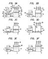
- the main raw material container 1 is secured to the bottom of the temperature-controlled bath 3 by means of supporting stands 4.
- Carrier gas 5 1 is introduced into the main raw material container, through pipe 5 and a flow control device 6, in the bubbling state.
- the gas 7' including the raw material gas in the saturated or nearly saturated state is passed to the reaction device through the pipe 7.
- a pipe 9 is coupled to the main raw material container for introducing initially and manually liquid raw material from a service tank. There is no need, however, to use this pipe in the normal and continuous running of the reaction device.
- Three liquid level detectors 24, 25 and 26 are provided in the main raw material container to detect a respective normal lowest liquid level, normal highest liquid level and abnormal uppermost liquid level (an emergency overflow level) of the liquid raw material.
- a secondary raw material container 12 is provided adjacent to the main raw material container. Both containers are connected at their bottoms or portions adjacent their bottoms by a pipe 30 which includes a manually or automatically operated switching valve 17 and a flow regulating valve (a needle valve) 16. To the secondary raw material container 12 there are coupled a pipe 13 for introducing . liquid raw material 13', a pipe 14 for introducing a pressurizing gas 14' to pressurize the secondary raw material container to force the liquid raw material out under pressure, and a pipe 15 for gas venting (purging). These pipes are provided with respective manually operated switching valves 18, 19 and 20 and automatic switching valves 21, 22 and 23. Similar to the main raw material container, liquid level detectors 27, 28 and 29 are provided.
- Figs. 3A to 3F indicate the operation of the foregoing raw material supply device.
- the shut-off valve 8 and the switching valve 18 are opened to charge the liquid raw material in the main raw material container and the secondary raw material container from the service tank.
- the switching valve 19 is opened to introduce pressurizing gas into the upper space of the secondary raw material container 12 so as to pressurize the latter.
- the switching valve 17 connecting the main raw material container and the secondary raw material container is opened.
- the carrier gas is introduced through the pipe 5 and supplying of the raw material gas is commenced through the pipe 7 to the reaction device.
- the flow rate of the liquid raw material flowing from the secondary raw material container into the main raw material container is controlled by the needle valve 16 so as to close to but somewhat larger than the flow rate of the raw material from the main raw material container to the reaction device, this is, the rate of consumption of the raw material. So controlled, the liquid level in the main raw material container rises gradually and the liquid level in the secondary raw material container lowers as shown in Fig. 3A. Because the rate of consumption of the raw material is generally small, the temperature, pressure and the like inside the main raw material container are maintained substantially constant even through liquid raw material is suppplemented from the secondary raw material container at a rate slightly larger than the consumption rate.
- the liquid level detector 25 operates to close the switching valve 17 and, in turn, to halt the supply from the secondary raw material container. Then, as the liquid level in the main raw material container lowers and reaches the lowest limit as shown in Fig. 3C, the liquid level detector 24 operates to open the switching valve 17 and, in turn, to commence again the supply of the liquid raw material to the secondary raw material container.
- the liquid level detector 27 operates to close the shut-off valve 17 and then to open the shut-off valve 20 so that the pressurizing gas is purged through the gas-venting pipe 15 of the secondary raw material container, and further to open the shut-off valve 18 so that liquid raw material 13' is supplemented from the service tank into the secondary raw material container 12.
- the liquid level detector 28 operates to close the shut-off valves 18 and 20 and open the shut-off valve 19 so that the pressurizing gas pressurizes the secondary raw material container.
- the shut-off valve 19 closes and the shut-off valve 17 opens, whereupon the system assumes the state shown in Fig. 3F and then returns to the state shown in Fig. 3A.
- the pressurizing gas is introduced when the liquid level in the secondary raw material container reaches the highest limit, the pressure in the secondary raw material container should be maintained at a level suffficient for the liquid raw material to be forced under pressure to the main raw material container even when the liquid level in the secondary raw material container reaches the lowest limit.
- the conditions of the liquid raw material in the main raw material container can be maintained more uniform if the secondary raw material container of the system is situated in a temperature-controlled bath so as to maintain the liquid temperature therein equal to or nearly equal to the temperature of the liquid raw material in the main raw material container and to open the shut-off valve 17 after having awaited stabilization of the temperature of the liquid raw material following liquid supplementation to the secondary raw material container.
- a heater can be provided midway of the pipe to thereby control the temperature of the liquid raw material flowing into the main raw material container so as to be equal to the temperature of the liquid raw material in the main raw material container.
- V s represented by equation (3) is understood to be controlled and maintained constant, as is apparent from equations (4), (5) and (7).
- the liquid raw material supplied from the secondary raw material container 12 to the gaseous phase portion is indicated by the arrow " ⁇ " in the drawing. If the liquid raw material were introduced intermittently or dripped into the main raw material container, and assuming each droplet evaporates before reaching the liquid surface, a partial pressure P s ' (;IPs) results which is determined solely by the latent heat of evaporation, and thus the ratio of partial pressures P s /P c of the gaseous portion in the container would be caused to vary. On the other hand, if the liquid droplet reaches the liquid surface, there would result disturbances on the liquid surface and variations in temperature, which are unfavorable. Further, if the raw material were introduced in the evaporated state into the main raw material container 1 with the connecting pipe 30 heated, maintaining the temperature of the heated vapor equal to that of the vapor in the main raw material container 2 would be remarkably difficult.
- the device of the invention does not change the state inside the main raw material container during supplementation of the liquid raw material, and thus the invention allows for continuous long-time operation of the reaction device. Moreover, the operating rate of the reaction device is increased, and the manufacture of preforms of large size is made possible. Further, by providing the liquid level detectors, liquid supplementation can be automated fully.
Landscapes
- Chemical & Material Sciences (AREA)
- Engineering & Computer Science (AREA)
- Chemical Kinetics & Catalysis (AREA)
- Organic Chemistry (AREA)
- General Chemical & Material Sciences (AREA)
- Materials Engineering (AREA)
- Automation & Control Theory (AREA)
- General Physics & Mathematics (AREA)
- Life Sciences & Earth Sciences (AREA)
- Physics & Mathematics (AREA)
- Geochemistry & Mineralogy (AREA)
- General Life Sciences & Earth Sciences (AREA)
- Manufacturing & Machinery (AREA)
- Mechanical Engineering (AREA)
- Metallurgy (AREA)
- Feeding, Discharge, Calcimining, Fusing, And Gas-Generation Devices (AREA)
- Organic Low-Molecular-Weight Compounds And Preparation Thereof (AREA)
- Manufacture, Treatment Of Glass Fibers (AREA)
Priority Applications (5)
| Application Number | Priority Date | Filing Date | Title |
|---|---|---|---|
| AU24076/84A AU563417B2 (en) | 1984-02-07 | 1984-02-03 | Optical fibre manufacture |
| US06/577,419 US4545801A (en) | 1984-02-07 | 1984-02-06 | Raw material supply device |
| CA000446953A CA1210243A (en) | 1984-02-07 | 1984-02-07 | Raw material supply device |
| DE8484101237T DE3465978D1 (en) | 1984-02-07 | 1984-02-07 | Raw material supply device |
| EP19840101237 EP0151200B1 (de) | 1984-02-07 | 1984-02-07 | Vorrichtung zum Speisen eines Rohmaterials |
Applications Claiming Priority (1)
| Application Number | Priority Date | Filing Date | Title |
|---|---|---|---|
| EP19840101237 EP0151200B1 (de) | 1984-02-07 | 1984-02-07 | Vorrichtung zum Speisen eines Rohmaterials |
Publications (2)
| Publication Number | Publication Date |
|---|---|
| EP0151200A1 true EP0151200A1 (de) | 1985-08-14 |
| EP0151200B1 EP0151200B1 (de) | 1987-09-09 |
Family
ID=8191754
Family Applications (1)
| Application Number | Title | Priority Date | Filing Date |
|---|---|---|---|
| EP19840101237 Expired EP0151200B1 (de) | 1984-02-07 | 1984-02-07 | Vorrichtung zum Speisen eines Rohmaterials |
Country Status (5)
| Country | Link |
|---|---|
| US (1) | US4545801A (de) |
| EP (1) | EP0151200B1 (de) |
| AU (1) | AU563417B2 (de) |
| CA (1) | CA1210243A (de) |
| DE (1) | DE3465978D1 (de) |
Cited By (4)
| Publication number | Priority date | Publication date | Assignee | Title |
|---|---|---|---|---|
| EP0283874A1 (de) * | 1987-03-19 | 1988-09-28 | MERCK PATENT GmbH | Vorrichtung zur Erzeugung eines Gasgemisches nach dem Sättigungsverfahren |
| EP0328888A1 (de) * | 1988-02-11 | 1989-08-23 | Siemens Aktiengesellschaft | Thermostatisierte Anordnung zur sicheren und kontrollierten Verdampfung von giftigen oder an der Luft hochreaktiven flüssigen Reaktionsmedien, vorzugsweise für Niederdruckdampfabscheideanlagen in der Halbleitertechnik |
| EP0635460A3 (de) * | 1993-07-22 | 1995-08-09 | Sumitomo Electric Industries | Vorrichtung zur Gaserzeugung und Verfahren und Vorrichtung zum Herstellen eines optischen Wellenleiters und einer optischen Faservorform. |
| EP2777067A4 (de) * | 2011-11-10 | 2016-03-30 | Saint Gobain Cristaux Et Detecteurs | System zur verwendung bei der erzeugung von halbleiterkristallmaterialien |
Families Citing this family (30)
| Publication number | Priority date | Publication date | Assignee | Title |
|---|---|---|---|---|
| US4676404A (en) * | 1983-10-17 | 1987-06-30 | Nippon Zeon Co., Ltd. | Method and apparatus for feeding drug liquid from hermetic returnable can |
| JPS61254242A (ja) * | 1985-05-01 | 1986-11-12 | Sumitomo Electric Ind Ltd | 原料供給装置 |
| US4859375A (en) * | 1986-12-29 | 1989-08-22 | Air Products And Chemicals, Inc. | Chemical refill system |
| JPS62273714A (ja) * | 1986-05-21 | 1987-11-27 | Clarion Co Ltd | 有機金属ガス供給方法および装置 |
| GB8708436D0 (en) * | 1987-04-08 | 1987-05-13 | British Telecomm | Reagent source |
| JP2846891B2 (ja) * | 1988-06-03 | 1999-01-13 | 東京エレクトロン株式会社 | 処理装置 |
| US4979545A (en) * | 1988-10-31 | 1990-12-25 | Olin Corporation | Bubbler container automatic refill system |
| EP0420596B1 (de) * | 1989-09-26 | 1996-06-19 | Canon Kabushiki Kaisha | Gasversorgungsvorrichtung und ihre Verwendung für eine Filmabscheidungsanlage |
| US5038840A (en) * | 1990-07-31 | 1991-08-13 | Olin Corporation | Bubbler container automatic refill system |
| JPH0692558A (ja) * | 1990-09-28 | 1994-04-05 | Otis Elevator Co | 発進時の揺れ及び過剰加速を低減するエレベータの発進制御装置 |
| US5252134A (en) * | 1991-05-31 | 1993-10-12 | Stauffer Craig M | Integrated delivery system for chemical vapor from non-gaseous sources for semiconductor processing |
| DE4236324C1 (de) * | 1992-10-28 | 1993-09-02 | Schott Glaswerke, 55122 Mainz, De | |
| IT1257434B (it) * | 1992-12-04 | 1996-01-17 | Cselt Centro Studi Lab Telecom | Generatore di vapori per impianti di deposizione chimica da fase vapore |
| US5399200A (en) * | 1994-03-10 | 1995-03-21 | Stauffer; Craig M. | Module in an integrated delivery system for chemical vapors from liquid sources |
| US5451258A (en) * | 1994-05-11 | 1995-09-19 | Materials Research Corporation | Apparatus and method for improved delivery of vaporized reactant gases to a reaction chamber |
| US6076541A (en) * | 1997-11-26 | 2000-06-20 | Pozniak; Peter M. | Dispensing system and method for dispensing an aqueous solution |
| KR100524204B1 (ko) * | 1998-01-07 | 2006-01-27 | 동경 엘렉트론 주식회사 | 가스 처리장치 |
| CA2331704C (en) * | 1999-03-04 | 2008-05-27 | Riken | Liquid treatment device with storage tank and delivery tank |
| JP2002143751A (ja) * | 2000-10-17 | 2002-05-21 | L'air Liquide Sa Pour L'etude & L'exploitation Des Procede S Georges Claude | 処理液分配装置及び方法 |
| US6736154B2 (en) * | 2001-01-26 | 2004-05-18 | American Air Liquide, Inc. | Pressure vessel systems and methods for dispensing liquid chemical compositions |
| US6790475B2 (en) * | 2002-04-09 | 2004-09-14 | Wafermasters Inc. | Source gas delivery |
| KR20040000689A (ko) * | 2002-06-25 | 2004-01-07 | 삼성전자주식회사 | 화학기상 증착공정의 원료물질 공급장치 |
| US7727588B2 (en) * | 2003-09-05 | 2010-06-01 | Yield Engineering Systems, Inc. | Apparatus for the efficient coating of substrates |
| EP1566464B1 (de) * | 2004-02-20 | 2011-04-13 | Cs Clean Systems Ag | Vorrichtung und Verfahren zum Nachfüllen eines Blasenverdampfers |
| WO2006113073A1 (en) * | 2005-04-12 | 2006-10-26 | E. I. Du Pont De Nemours And Company | System for accurately weighing solids and control mechanism for same |
| TWM352764U (en) * | 2008-06-19 | 2009-03-11 | Scientech Corp | Constant temperature gas/liquid mixture generating system for using in wafer drying process |
| US8555809B2 (en) * | 2010-01-14 | 2013-10-15 | Rohm And Haas Electronic Materials, Llc | Method for constant concentration evaporation and a device using the same |
| KR102111020B1 (ko) * | 2013-05-02 | 2020-05-15 | 삼성디스플레이 주식회사 | 증착 장치 |
| US9957612B2 (en) * | 2014-01-17 | 2018-05-01 | Ceres Technologies, Inc. | Delivery device, methods of manufacture thereof and articles comprising the same |
| US12629735B2 (en) | 2019-06-24 | 2026-05-19 | Komar Industries. LLC | System and method for separation of organics and liquids from waste material |
Citations (4)
| Publication number | Priority date | Publication date | Assignee | Title |
|---|---|---|---|---|
| US4220460A (en) * | 1979-02-05 | 1980-09-02 | Western Electric Company, Inc. | Vapor delivery system and method |
| US4276243A (en) * | 1978-12-08 | 1981-06-30 | Western Electric Company, Inc. | Vapor delivery control system and method |
| EP0040540A2 (de) * | 1980-05-20 | 1981-11-25 | J.C. Schumacher Company | Chemisches Dampf-Liefersystem und Verfahren zum Steuern des Dampfflusses in einem chemischen Dampf-Liefersystem |
| EP0063847A1 (de) * | 1981-04-29 | 1982-11-03 | Koninklijke Philips Electronics N.V. | Verfahren zur Sättigung eines Gases mit dem Dampf einer Flüssigkeit |
Family Cites Families (7)
| Publication number | Priority date | Publication date | Assignee | Title |
|---|---|---|---|---|
| US2376694A (en) * | 1942-10-03 | 1945-05-22 | Allen M Hewlett | Automatic diverter for sugar contaminated condensates |
| US3084708A (en) * | 1960-01-05 | 1963-04-09 | Herrero Leonidas Gil De Gibaja | Water level control system |
| US3195464A (en) * | 1963-05-29 | 1965-07-20 | Flint Pump & Equipment Co | Air control system for liquid storage tanks |
| US3473959A (en) * | 1964-08-10 | 1969-10-21 | Licentia Gmbh | Method for coating semiconductors and apparatus |
| US3901182A (en) * | 1972-05-18 | 1975-08-26 | Harris Corp | Silicon source feed process |
| US4314837A (en) * | 1979-03-01 | 1982-02-09 | Corning Glass Works | Reactant delivery system method |
| DE2908283C3 (de) * | 1979-03-03 | 1982-02-04 | Mathias Bäuerle GmbH, 7742 St Georgen | Elektrisch betriebenes Gerät, insbesondere Vervielfältigungsgerät, mit einem mit Flüssigkeit zum chemischen Behandeln von Gegenständen aufnehmenden Behälter |
-
1984
- 1984-02-03 AU AU24076/84A patent/AU563417B2/en not_active Expired
- 1984-02-06 US US06/577,419 patent/US4545801A/en not_active Expired - Lifetime
- 1984-02-07 EP EP19840101237 patent/EP0151200B1/de not_active Expired
- 1984-02-07 DE DE8484101237T patent/DE3465978D1/de not_active Expired
- 1984-02-07 CA CA000446953A patent/CA1210243A/en not_active Expired
Patent Citations (4)
| Publication number | Priority date | Publication date | Assignee | Title |
|---|---|---|---|---|
| US4276243A (en) * | 1978-12-08 | 1981-06-30 | Western Electric Company, Inc. | Vapor delivery control system and method |
| US4220460A (en) * | 1979-02-05 | 1980-09-02 | Western Electric Company, Inc. | Vapor delivery system and method |
| EP0040540A2 (de) * | 1980-05-20 | 1981-11-25 | J.C. Schumacher Company | Chemisches Dampf-Liefersystem und Verfahren zum Steuern des Dampfflusses in einem chemischen Dampf-Liefersystem |
| EP0063847A1 (de) * | 1981-04-29 | 1982-11-03 | Koninklijke Philips Electronics N.V. | Verfahren zur Sättigung eines Gases mit dem Dampf einer Flüssigkeit |
Cited By (4)
| Publication number | Priority date | Publication date | Assignee | Title |
|---|---|---|---|---|
| EP0283874A1 (de) * | 1987-03-19 | 1988-09-28 | MERCK PATENT GmbH | Vorrichtung zur Erzeugung eines Gasgemisches nach dem Sättigungsverfahren |
| EP0328888A1 (de) * | 1988-02-11 | 1989-08-23 | Siemens Aktiengesellschaft | Thermostatisierte Anordnung zur sicheren und kontrollierten Verdampfung von giftigen oder an der Luft hochreaktiven flüssigen Reaktionsmedien, vorzugsweise für Niederdruckdampfabscheideanlagen in der Halbleitertechnik |
| EP0635460A3 (de) * | 1993-07-22 | 1995-08-09 | Sumitomo Electric Industries | Vorrichtung zur Gaserzeugung und Verfahren und Vorrichtung zum Herstellen eines optischen Wellenleiters und einer optischen Faservorform. |
| EP2777067A4 (de) * | 2011-11-10 | 2016-03-30 | Saint Gobain Cristaux Et Detecteurs | System zur verwendung bei der erzeugung von halbleiterkristallmaterialien |
Also Published As
| Publication number | Publication date |
|---|---|
| US4545801A (en) | 1985-10-08 |
| EP0151200B1 (de) | 1987-09-09 |
| CA1210243A (en) | 1986-08-26 |
| AU2407684A (en) | 1985-08-08 |
| AU563417B2 (en) | 1987-07-09 |
| DE3465978D1 (en) | 1987-10-15 |
Similar Documents
| Publication | Publication Date | Title |
|---|---|---|
| US4545801A (en) | Raw material supply device | |
| US4582480A (en) | Methods of and apparatus for vapor delivery control in optical preform manufacture | |
| US7025337B2 (en) | Method for maintaining a constant level of fluid in a liquid vapor delivery system | |
| US4235829A (en) | Vapor delivery system and method of maintaining a constant level of liquid therein | |
| EP0018068B1 (de) | Regelbare Aufdampfquelle | |
| US6161398A (en) | Methods of and systems for vapor delivery control in optical preform manufacture | |
| US4861524A (en) | Apparatus for producing a gas mixture by the saturation method | |
| Hersee et al. | The operation of metalorganic bubblers at reduced pressure | |
| EP0165493B1 (de) | Nachfülleinrichtung für Flüssigkeiten | |
| JPH05291142A (ja) | 液体ソース供給装置 | |
| CN209759579U (zh) | 一种新型液态源汽化装置 | |
| EP0200215B1 (de) | Vorrichtung zum Liefern eines Rohstoffs und Verfahren zur Benutzung dieser Vorrichtung | |
| GB2073453A (en) | Control of vapour flow | |
| EP1517863A1 (de) | Verfahren und vorrichtung zum verdampfen eines flüssigen vorlaüfers beim herstellen einer glasvorform | |
| WO1987001614A1 (en) | Vacuum vapor transport control | |
| CN211946809U (zh) | 一种高精度的四氯化锗鼓泡装置 | |
| US3086849A (en) | Apparatus for carrying out chemical process | |
| JPH085690B2 (ja) | 原料供給方法および装置 | |
| US2862947A (en) | Continuous process for the preparation of dithiophosphate acid esters | |
| JPS60251144A (ja) | 光学系ガラス原料のバブリング装置 | |
| US4894079A (en) | Method and apparatus for supplying glass forming raw material | |
| JPS59116140A (ja) | 原料供給装置 | |
| JPS58659Y2 (ja) | 光フアイバ母材製造用原料供給装置 | |
| CN217323853U (zh) | 自动化制氢系统 | |
| JPS62235227A (ja) | 光フアイバ用母材の製造方法 |
Legal Events
| Date | Code | Title | Description |
|---|---|---|---|
| PUAI | Public reference made under article 153(3) epc to a published international application that has entered the european phase |
Free format text: ORIGINAL CODE: 0009012 |
|
| 17P | Request for examination filed |
Effective date: 19850117 |
|
| AK | Designated contracting states |
Kind code of ref document: A1 Designated state(s): DE FR GB IT Designated state(s): DE FR GB IT |
|
| RAP1 | Party data changed (applicant data changed or rights of an application transferred) |
Owner name: NIPPON TELEGRAPH AND TELEPHONE PUBLIC CORPORATION Owner name: NIPPON TELEGRAPH AND TELEPHONE CORPORATION |
|
| RAP1 | Party data changed (applicant data changed or rights of an application transferred) |
Owner name: NIPPON TELEGRAPH AND TELEPHONE CORPORATION Owner name: SUMITOMO ELECTRIC INDUSTRIES LIMITED |
|
| 17Q | First examination report despatched |
Effective date: 19860603 |
|
| GRAA | (expected) grant |
Free format text: ORIGINAL CODE: 0009210 |
|
| AK | Designated contracting states |
Kind code of ref document: B1 Designated state(s): DE FR GB IT |
|
| REF | Corresponds to: |
Ref document number: 3465978 Country of ref document: DE Date of ref document: 19871015 |
|
| ET | Fr: translation filed | ||
| ITF | It: translation for a ep patent filed | ||
| PLBE | No opposition filed within time limit |
Free format text: ORIGINAL CODE: 0009261 |
|
| STAA | Information on the status of an ep patent application or granted ep patent |
Free format text: STATUS: NO OPPOSITION FILED WITHIN TIME LIMIT |
|
| 26N | No opposition filed | ||
| ITTA | It: last paid annual fee | ||
| REG | Reference to a national code |
Ref country code: GB Ref legal event code: IF02 |
|
| PGFP | Annual fee paid to national office [announced via postgrant information from national office to epo] |
Ref country code: GB Payment date: 20030205 Year of fee payment: 20 |
|
| PGFP | Annual fee paid to national office [announced via postgrant information from national office to epo] |
Ref country code: FR Payment date: 20030210 Year of fee payment: 20 |
|
| PGFP | Annual fee paid to national office [announced via postgrant information from national office to epo] |
Ref country code: DE Payment date: 20030220 Year of fee payment: 20 |
|
| PG25 | Lapsed in a contracting state [announced via postgrant information from national office to epo] |
Ref country code: GB Free format text: LAPSE BECAUSE OF EXPIRATION OF PROTECTION Effective date: 20040206 |
|
| REG | Reference to a national code |
Ref country code: GB Ref legal event code: PE20 |