EP0151740A2 - Sélecteur de charge pour transformateurs à prises - Google Patents
Sélecteur de charge pour transformateurs à prises Download PDFInfo
- Publication number
- EP0151740A2 EP0151740A2 EP84115085A EP84115085A EP0151740A2 EP 0151740 A2 EP0151740 A2 EP 0151740A2 EP 84115085 A EP84115085 A EP 84115085A EP 84115085 A EP84115085 A EP 84115085A EP 0151740 A2 EP0151740 A2 EP 0151740A2
- Authority
- EP
- European Patent Office
- Prior art keywords
- contact
- contacts
- guide rails
- switching
- slide
- Prior art date
- Legal status (The legal status is an assumption and is not a legal conclusion. Google has not performed a legal analysis and makes no representation as to the accuracy of the status listed.)
- Granted
Links
Images

Classifications
-
- H—ELECTRICITY
- H01—ELECTRIC ELEMENTS
- H01H—ELECTRIC SWITCHES; RELAYS; SELECTORS; EMERGENCY PROTECTIVE DEVICES
- H01H9/00—Details of switching devices, not covered by groups H01H1/00 - H01H7/00
- H01H9/0005—Tap change devices
- H01H9/0016—Contact arrangements for tap changers
Definitions
- the invention relates to load selectors for step transformers for switching from one tap to the next with fixed step contacts arranged on a circuit, connected to the taps, and with switching contacts of three current branches on a common contact carrier, which are simultaneously pivotable on the circuit and shown by contact rollers.
- the respective outer switching contacts are in series with a series resistor. This results in the so-called "flag switching", which is particularly favorable with regard to the switching power that is controlled at the individual contacts.
- the operating current of the transformer flows from a fixed contact via the main switch contact located in the middle, while the two outer switch contacts represent resistance contacts and are de-energized in the rest position of the load selector.
- at least one of the movable switch contacts must be in contact with a fixed contact in each intermediate position during the adjustment process. This means that in an intermediate position one resistance contact must run onto the current-carrying fixed contact earlier than the main switching contact runs from this fixed contact. Accordingly, the second resistance contact must already touch the following fixed contact before the current-carrying resistance contact runs out of the fixed contact which was current-carrying up to that point.
- the width of the fixed contacts must be greater than half the distance from contact rollers which represent resistance contacts the distance between these contact rollers must be greater than the distance between two adjacent, fixed contacts.
- a disadvantage of the first-mentioned contact arrangement is the relatively bulky structure, which additionally complicates use when very high operating voltages occur.
- the contact arrangement with contact rollers mounted on angle levers is unsatisfactory insofar as it requires different cam tracks for controlling the individual contacts assigned to the same contact carrier. This results in a relatively large manufacturing effort, which is further increased by the need to take into account the possible manufacturing tolerances that occur.
- the invention is based on the object of creating a contact arrangement for load selectors which has a compact structure and enables a largely smooth-surface design for the contact carrier and the fixed contacts, and at the same time also permits greater manufacturing tolerances.
- the contact carrier has guide rails aligned radially in the circle of the stepped contacts for at least two contact slides, in that a first contact slide carries a main switching contact and at least one other contact slide carries two resistance contacts flanking the main switching contact in the pivoting direction on both sides , that operationally occurring, opposite movements of the contact slides on the guide rails by stops on the contact carriage itself are limited in both directions, so that when the stops lie against each other all the spring contacts assigned to the switch contacts load the current-carrying switch contact, and that the guide rails and the contact slide interlock telescopically.
- the contact slide carrying the main switching contact is arranged between two guide rails and that a box-like contact slide comprising this arrangement serves as a common carrier for the two resistance contacts.
- pins projecting transversely to the pivoting direction from the contact slide carrying the main switch contact engage in elongated holes in the box-like contact slide and, together with the ends of the elongated holes, represent the stops for limiting the slide movements in the radial direction.
- each of the contact carriages is constantly pressed radially outwards by spring force, that an end stop for the box-like contact carriage is provided on at least one guide rail, which secures the contact carriage during assembly before sliding off the guide rails.
- the main switching contact consists of two contact rollers arranged spatially one behind the other in the switching direction, each on a contact carriage which is displaceable per se, and / or that the contact carriages are supported among one another and on the guide rails via roller bearings.
- the features according to the invention enable a very advantageous, simple structure for a load selector, because in the rest position and in the first part of the switching process, the main switch contact and the switch slide assigned to it are supported on the fixed contact and because as long as neither of the two resistance contact rollers touches one of the fixed contacts the switching slide of the resistance contacts is supported radially on the switching slide of the main switching contacts. Sobala, however, the contact role of the main switch contact has expired from the fixed contact, the switching slide of the main switching contact is supported radially on the switching slide of the resistance contacts, so that both switching slides are then supported radially via the resistance contact roll just touching a fixed contact.
- Fixed step contacts 1 are arranged in a known manner, not shown, on a circle, wherein they are carried by insulating rods or an insulating cylinder forming a cylindrical cage.
- the fixed step contacts 1 are galvanically connected to taps of a fine step winding.
- a main switch contact is located on each of the step contacts 1, which in turn is galvanically connected to a load line.
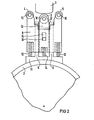
- the main switch contact 3 is formed by a roller rotatably mounted on an axis 10 and, together with a contact slide 13 between guide rails 6, can be displaced in the radial direction until the roller contacts the step contact 1 by means of a spring 14.
- the guide rails 6 are parts of a frame 11, which in turn is supported by an insulating tube 2 mounted centrally to the cage. The insulating tube 2 is rotated in a manner not shown via a step-by-step manual transmission.
- the frame 11 with the guide rails 6 and the contact slide 13 are surrounded by a box-shaped contact slide 9.
- the contact slide 9 carries the main switch contact 3 flanking in the direction of the switching movement of the resistance contacts 4 and 5 on the axles 10 fastened in it.
- Each of the resistance contacts 4 and 5 usually forms a series connection with a series resistor, which in turn is in each case parallel to the main switching contact 3, so that they are at certain Switch positions leads the load current between one or briefly two stage contacts 1 and the load line, not shown.
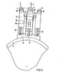
- the box-like contact slide 9 is pushed by compression springs 12 in the direction of the fixed step contacts 1. To limit this movement, pins 16 protruding transversely to the switching direction from the contact slide 13, which engage in elongated holes 15 in the contact slide 9. 2, the switching slide 9 is supported radially and the contact force exerted by the compression spring 14 on the main switching contact 3 is increased by adding the forces generated by the compression springs 12.
- end stops 17 are provided at the end of at least one of the guide rails, which the radial Limit displacement of the contact carriage 9 and thereby also indirectly hold the contact carriage 13 via the pins 16 projecting into the elongated holes 15.
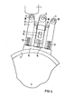
- both resistance contacts 4 and 5 are again next to the fixed tap contact 1, which then carries the current, so that they, together with the contact carriage 9, are pushed radially outwards by the compression springs 12 to such an extent that the pins 16 at the inner ends of the elongated holes 15 and the spring forces of the compression springs 12 contribute to increasing the contact force for the main switching contact 3.
- the opening and closing of the contact can roll so that the contact role of the main switch contact 3 always runs and runs on the outer edges of the fixed step contact 1, while the roles of the resistance contacts 4 and 5 each run or run approximately halfway between the outer edge and the center of the fixed contacts.
- the erosion caused by the arc on the surface of the fixed contacts can be distributed over a larger total area of this surface than if, for example, all three contact rollers run up and down on the outer edges of the fixed contacts.
Landscapes
- Contacts (AREA)
- Forklifts And Lifting Vehicles (AREA)
- Protection Of Transformers (AREA)
- Regulation Of General Use Transformers (AREA)
- Electronic Switches (AREA)
- Vehicle Body Suspensions (AREA)
Priority Applications (1)
| Application Number | Priority Date | Filing Date | Title |
|---|---|---|---|
| AT84115085T ATE52357T1 (de) | 1984-01-16 | 1984-12-10 | Lastwaehler fuer stufentransformatoren. |
Applications Claiming Priority (2)
| Application Number | Priority Date | Filing Date | Title |
|---|---|---|---|
| DE19843401297 DE3401297A1 (de) | 1984-01-16 | 1984-01-16 | Lastwaehler fuer stufentransformatoren |
| DE3401297 | 1984-01-16 |
Publications (3)
| Publication Number | Publication Date |
|---|---|
| EP0151740A2 true EP0151740A2 (fr) | 1985-08-21 |
| EP0151740A3 EP0151740A3 (en) | 1987-11-19 |
| EP0151740B1 EP0151740B1 (fr) | 1990-04-25 |
Family
ID=6225071
Family Applications (1)
| Application Number | Title | Priority Date | Filing Date |
|---|---|---|---|
| EP84115085A Expired - Lifetime EP0151740B1 (fr) | 1984-01-16 | 1984-12-10 | Sélecteur de charge pour transformateurs à prises |
Country Status (4)
| Country | Link |
|---|---|
| EP (1) | EP0151740B1 (fr) |
| JP (1) | JPS60161604A (fr) |
| AT (1) | ATE52357T1 (fr) |
| DE (2) | DE3401297A1 (fr) |
Cited By (4)
| Publication number | Priority date | Publication date | Assignee | Title |
|---|---|---|---|---|
| US4978815A (en) * | 1988-09-29 | 1990-12-18 | Maschinenfabrik Reinhausen Gmbh | Load selector for step transformers |
| US6998547B2 (en) | 2003-03-19 | 2006-02-14 | Maschinenfabrik Reinhausen Gmbh | On-load tap changer for a sequence switch |
| CN103314422A (zh) * | 2011-01-20 | 2013-09-18 | 赖茵豪森机械制造公司 | 分接开关 |
| DE102010020040B4 (de) * | 2010-05-11 | 2016-06-09 | Maschinenfabrik Reinhausen Gmbh | Schaltanordnung für einen Transformator mit einer an einer Schaltwelle befestigten Kontaktanordnung mit mehreren Kontaktelementen |
Families Citing this family (2)
| Publication number | Priority date | Publication date | Assignee | Title |
|---|---|---|---|---|
| DE3416050A1 (de) * | 1984-04-30 | 1985-10-31 | Transformatoren Union Ag, 7000 Stuttgart | Lastwaehler fuer stufentransformatoren |
| CN106992066B (zh) * | 2017-05-08 | 2018-09-18 | 国网浙江省电力公司温州供电公司 | 一种主动式有源降噪装置 |
Family Cites Families (3)
| Publication number | Priority date | Publication date | Assignee | Title |
|---|---|---|---|---|
| NL155138C (fr) * | 1950-08-01 | |||
| DE2914928C2 (de) * | 1979-04-12 | 1983-02-24 | Maschinenfabrik Reinhausen Gebrüder Scheubeck GmbH & Co KG, 8400 Regensburg | Kontaktanordnung für Lastwähler von Stufentransformatoren |
| DE2967539D1 (en) * | 1979-11-21 | 1985-12-05 | Acec | Electrical apparatus comprising a series of voltage taps and mobile selector equipment |
-
1984
- 1984-01-16 DE DE19843401297 patent/DE3401297A1/de not_active Withdrawn
- 1984-12-10 AT AT84115085T patent/ATE52357T1/de not_active IP Right Cessation
- 1984-12-10 EP EP84115085A patent/EP0151740B1/fr not_active Expired - Lifetime
- 1984-12-10 DE DE8484115085T patent/DE3482074D1/de not_active Expired - Fee Related
-
1985
- 1985-01-14 JP JP60004805A patent/JPS60161604A/ja active Pending
Cited By (7)
| Publication number | Priority date | Publication date | Assignee | Title |
|---|---|---|---|---|
| US4978815A (en) * | 1988-09-29 | 1990-12-18 | Maschinenfabrik Reinhausen Gmbh | Load selector for step transformers |
| US6998547B2 (en) | 2003-03-19 | 2006-02-14 | Maschinenfabrik Reinhausen Gmbh | On-load tap changer for a sequence switch |
| WO2004084241A3 (fr) * | 2003-03-19 | 2006-02-23 | Reinhausen Maschf Scheubeck | Commutateur de reglage en charge pour combinateur |
| CN100437854C (zh) * | 2003-03-19 | 2008-11-26 | 赖茵豪森机械制造公司 | 用于分接开关的负荷变换器 |
| KR101015495B1 (ko) | 2003-03-19 | 2011-02-22 | 마쉬넨파브릭 레인하우센 게엠베하 | 시퀀스 스위치용 부하시 탭 절환장치 |
| DE102010020040B4 (de) * | 2010-05-11 | 2016-06-09 | Maschinenfabrik Reinhausen Gmbh | Schaltanordnung für einen Transformator mit einer an einer Schaltwelle befestigten Kontaktanordnung mit mehreren Kontaktelementen |
| CN103314422A (zh) * | 2011-01-20 | 2013-09-18 | 赖茵豪森机械制造公司 | 分接开关 |
Also Published As
| Publication number | Publication date |
|---|---|
| DE3482074D1 (de) | 1990-05-31 |
| EP0151740A3 (en) | 1987-11-19 |
| JPS60161604A (ja) | 1985-08-23 |
| ATE52357T1 (de) | 1990-05-15 |
| DE3401297A1 (de) | 1985-07-18 |
| EP0151740B1 (fr) | 1990-04-25 |
Similar Documents
| Publication | Publication Date | Title |
|---|---|---|
| DE3833126C2 (de) | Lastwähler für Stufentransformatoren | |
| EP1105896B1 (fr) | Commutateur a gradins avec preselecteur | |
| EP1078380B1 (fr) | Commutateur de charge | |
| EP3286774B1 (fr) | Changeur de prises en charge, procédé d'actionnement d'un changeur de prises en charge et installation électrique le comprenant | |
| EP2481065A1 (fr) | Commutateur à gradins à tubes commutateurs à vide | |
| EP0650637A1 (fr) | Commutateur a gradins. | |
| DE102011119318B4 (de) | Stufenschalter mit Vakuumschaltröhren | |
| EP2815413A1 (fr) | Commutateur de prises en charge avec au moins deux vacuostats et actionnement pour un commutateur de prises en charge avec au moins deux vacuostats | |
| EP0151740B1 (fr) | Sélecteur de charge pour transformateurs à prises | |
| DE102020105113B3 (de) | Schalter für einen laststufenschalter und lastumschalter für einen laststufenschalter | |
| DE19501529C1 (de) | Umschaltanordnung | |
| EP0132662B1 (fr) | Sélecteur de charge pour transformateurs à échelons | |
| EP4042462B1 (fr) | Sélecteur pour changeur de prises en charge | |
| DE3409077C2 (fr) | ||
| DE3407332C2 (fr) | ||
| EP0213461A1 (fr) | Transformateur de réglage avec prise médiane | |
| DE202011110140U1 (de) | Schaltelement und Laststufenschalter mit einem solchen Schaltelement | |
| EP4200886B1 (fr) | Changeur de prises en charge et procédé pour actionner un changeur de prises en charge | |
| DE2535114C3 (de) | Dreiphasiger zylindrischer Lastumschalter | |
| EP1248276B1 (fr) | Organe de commande pour contrôler les contacts d'un disjoncteur d'un dispositif de coupure électrique | |
| DE2620211B2 (de) | Vorwähler für Stufenschalter von Einstelltransformatoren | |
| DE2359628C3 (de) | Wender zum Umschalten der Fein- oder Grobstufenwicklung eines mit einem Stufenschalter ausgerüsteten Transformators | |
| DE683960C (de) | Umschalter, insbesondere Lastwaehlerumschalter fuer Anzapftransformatoren | |
| WO2013007437A1 (fr) | Elément de commutation et changeur de prises en charge avec un tel élément de commutation | |
| DE2949463B2 (de) | Schaltanordnung zur Querspannungsregelung eines dreiphasigen Stufentransformators |
Legal Events
| Date | Code | Title | Description |
|---|---|---|---|
| PUAI | Public reference made under article 153(3) epc to a published international application that has entered the european phase |
Free format text: ORIGINAL CODE: 0009012 |
|
| AK | Designated contracting states |
Designated state(s): AT BE CH DE FR GB LI SE |
|
| RAP1 | Party data changed (applicant data changed or rights of an application transferred) |
Owner name: TRANSFORMATOREN UNION AKTIENGESELLSCHAFT |
|
| PUAL | Search report despatched |
Free format text: ORIGINAL CODE: 0009013 |
|
| RAP1 | Party data changed (applicant data changed or rights of an application transferred) |
Owner name: SIEMENS AKTIENGESELLSCHAFT BERLIN UND MUENCHEN |
|
| AK | Designated contracting states |
Kind code of ref document: A3 Designated state(s): AT BE CH DE FR GB LI SE |
|
| 17P | Request for examination filed |
Effective date: 19871204 |
|
| 17Q | First examination report despatched |
Effective date: 19890811 |
|
| GRAA | (expected) grant |
Free format text: ORIGINAL CODE: 0009210 |
|
| RAP1 | Party data changed (applicant data changed or rights of an application transferred) |
Owner name: MASCHINENFABRIK REINHAUSEN GMBH |
|
| AK | Designated contracting states |
Kind code of ref document: B1 Designated state(s): AT BE CH DE FR GB LI SE |
|
| REF | Corresponds to: |
Ref document number: 52357 Country of ref document: AT Date of ref document: 19900515 Kind code of ref document: T |
|
| GBT | Gb: translation of ep patent filed (gb section 77(6)(a)/1977) | ||
| REF | Corresponds to: |
Ref document number: 3482074 Country of ref document: DE Date of ref document: 19900531 |
|
| ET | Fr: translation filed | ||
| PG25 | Lapsed in a contracting state [announced via postgrant information from national office to epo] |
Ref country code: BE Effective date: 19901231 |
|
| PLBE | No opposition filed within time limit |
Free format text: ORIGINAL CODE: 0009261 |
|
| STAA | Information on the status of an ep patent application or granted ep patent |
Free format text: STATUS: NO OPPOSITION FILED WITHIN TIME LIMIT |
|
| 26N | No opposition filed | ||
| BERE | Be: lapsed |
Owner name: MASCHINENFABRIK REINHAUSEN G.M.B.H. Effective date: 19901231 |
|
| PGFP | Annual fee paid to national office [announced via postgrant information from national office to epo] |
Ref country code: GB Payment date: 19920922 Year of fee payment: 9 |
|
| PGFP | Annual fee paid to national office [announced via postgrant information from national office to epo] |
Ref country code: FR Payment date: 19921005 Year of fee payment: 9 |
|
| PGFP | Annual fee paid to national office [announced via postgrant information from national office to epo] |
Ref country code: AT Payment date: 19921030 Year of fee payment: 9 |
|
| PGFP | Annual fee paid to national office [announced via postgrant information from national office to epo] |
Ref country code: CH Payment date: 19921123 Year of fee payment: 9 |
|
| PGFP | Annual fee paid to national office [announced via postgrant information from national office to epo] |
Ref country code: SE Payment date: 19921204 Year of fee payment: 9 |
|
| PGFP | Annual fee paid to national office [announced via postgrant information from national office to epo] |
Ref country code: DE Payment date: 19921208 Year of fee payment: 9 |
|
| PG25 | Lapsed in a contracting state [announced via postgrant information from national office to epo] |
Ref country code: GB Effective date: 19931210 Ref country code: AT Effective date: 19931210 |
|
| PG25 | Lapsed in a contracting state [announced via postgrant information from national office to epo] |
Ref country code: SE Effective date: 19931211 |
|
| PG25 | Lapsed in a contracting state [announced via postgrant information from national office to epo] |
Ref country code: LI Effective date: 19931231 Ref country code: CH Effective date: 19931231 |
|
| GBPC | Gb: european patent ceased through non-payment of renewal fee |
Effective date: 19931210 |
|
| PG25 | Lapsed in a contracting state [announced via postgrant information from national office to epo] |
Ref country code: FR Effective date: 19940831 |
|
| REG | Reference to a national code |
Ref country code: CH Ref legal event code: PL |
|
| PG25 | Lapsed in a contracting state [announced via postgrant information from national office to epo] |
Ref country code: DE Effective date: 19940901 |
|
| REG | Reference to a national code |
Ref country code: FR Ref legal event code: ST |
|
| EUG | Se: european patent has lapsed |
Ref document number: 84115085.7 Effective date: 19940710 |