EP0151918A2 - Verfahren und Anordnung zur Kühlung von Hochtemperaturbauten mit einem Fluidkühlmittel - Google Patents
Verfahren und Anordnung zur Kühlung von Hochtemperaturbauten mit einem Fluidkühlmittel Download PDFInfo
- Publication number
- EP0151918A2 EP0151918A2 EP85100016A EP85100016A EP0151918A2 EP 0151918 A2 EP0151918 A2 EP 0151918A2 EP 85100016 A EP85100016 A EP 85100016A EP 85100016 A EP85100016 A EP 85100016A EP 0151918 A2 EP0151918 A2 EP 0151918A2
- Authority
- EP
- European Patent Office
- Prior art keywords
- passageway
- wall
- cusp
- gas
- coolant
- Prior art date
- Legal status (The legal status is an assumption and is not a legal conclusion. Google has not performed a legal analysis and makes no representation as to the accuracy of the status listed.)
- Withdrawn
Links
Images
Classifications
-
- F—MECHANICAL ENGINEERING; LIGHTING; HEATING; WEAPONS; BLASTING
- F02—COMBUSTION ENGINES; HOT-GAS OR COMBUSTION-PRODUCT ENGINE PLANTS
- F02K—JET-PROPULSION PLANTS
- F02K1/00—Plants characterised by the form or arrangement of the jet pipe or nozzle; Jet pipes or nozzles peculiar thereto
- F02K1/78—Other construction of jet pipes
- F02K1/82—Jet pipe walls, e.g. liners
- F02K1/822—Heat insulating structures or liners, cooling arrangements, e.g. post combustion liners; Infrared radiation suppressors
-
- F—MECHANICAL ENGINEERING; LIGHTING; HEATING; WEAPONS; BLASTING
- F01—MACHINES OR ENGINES IN GENERAL; ENGINE PLANTS IN GENERAL; STEAM ENGINES
- F01D—NON-POSITIVE DISPLACEMENT MACHINES OR ENGINES, e.g. STEAM TURBINES
- F01D5/00—Blades; Blade-carrying members; Heating, heat-insulating, cooling or antivibration means on the blades or the members
- F01D5/12—Blades
- F01D5/14—Form or construction
- F01D5/18—Hollow blades, i.e. blades with cooling or heating channels or cavities; Heating, heat-insulating or cooling means on blades
- F01D5/186—Film cooling
-
- F—MECHANICAL ENGINEERING; LIGHTING; HEATING; WEAPONS; BLASTING
- F23—COMBUSTION APPARATUS; COMBUSTION PROCESSES
- F23R—GENERATING COMBUSTION PRODUCTS OF HIGH PRESSURE OR HIGH VELOCITY, e.g. GAS-TURBINE COMBUSTION CHAMBERS
- F23R3/00—Continuous combustion chambers using liquid or gaseous fuel
- F23R3/02—Continuous combustion chambers using liquid or gaseous fuel characterised by the air-flow or gas-flow configuration
- F23R3/04—Air inlet arrangements
- F23R3/06—Arrangement of apertures along the flame tube
-
- Y—GENERAL TAGGING OF NEW TECHNOLOGICAL DEVELOPMENTS; GENERAL TAGGING OF CROSS-SECTIONAL TECHNOLOGIES SPANNING OVER SEVERAL SECTIONS OF THE IPC; TECHNICAL SUBJECTS COVERED BY FORMER USPC CROSS-REFERENCE ART COLLECTIONS [XRACs] AND DIGESTS
- Y02—TECHNOLOGIES OR APPLICATIONS FOR MITIGATION OR ADAPTATION AGAINST CLIMATE CHANGE
- Y02T—CLIMATE CHANGE MITIGATION TECHNOLOGIES RELATED TO TRANSPORTATION
- Y02T50/00—Aeronautics or air transport
- Y02T50/60—Efficient propulsion technologies, e.g. for aircraft
Definitions
- the invention relates to a method and apparatus for cooling high temperature structures with a fluid coolant such as air and is directed more particularly to a method and apparatus for establishing a layer of low temperature fluid between a hot flowing fluid and a wall subject to the hot fluid.
- a fluid coolant such as air
- film cooling Such cooling is known as "film cooling”.
- Film cooling of the surfaces of combustor walls and turbine or stator blades in gas turbine engines and jet engines is generally well-known.
- slanted circular apertures or passageways are provided in the combustor wall or in the turbine blade wall.
- a coolant fluid such as air under pressure is applied to one side of a wall whereby it is injected at an acute angle to a hot flowing gas on the other side of the wall. The coolant displaces the hot flowing gas to form a layer of coolang between the wall and the hot gas.
- a coolant layer for film cooling structures extends in a downstream direction from each passageway for a distance determined by the amount of mixing or blending of the coolant and the hot gas. After the coolant and the hot gas are thoroughly mixed, of course, the cooling effect is lost. Further, immediately downstream of each passageway there is normally a separation of the coolant from the wall. This results in an undesirably high temperature immediately downstream of each passageway.
- the mixing of the coolant in the hot gas must be minimized to extend the coolant layer a maximum distance in the downstream direction. Further, separation of the coolant gas from the wall to be cooled must be minimized or eliminated immediately downstream of each passageway. Additionally, reduction of the energy extracted from the hot flowing gas to effect film cooling is highly desirable. This makes more energy available to turn the coolant jet closer to the wall.
- U.S. Patent No. 3,742,706 to Klompas discloses turbine blading in which a portion of the high pressure compressor discharge airflow is directed to cool the most critical temperature areas of a turbine blade and a portion of the low pressure compressor interstage airflow is directed to cool the less critical temperature areas of the-same turbine blade.
- U.S. Patent No. 3,437,313 to Moore discloses a gas turbine in which the air delivered to a turbine rotor disc for delivery to cooling passages in the turbine blades is at a higher pressure than the gas passing over and driving the turbine blades.
- a projection extends into the gas flow and uses same of the dynamic pressure head of the gas flow to resist the escape of cooling air into the gas flow.
- U.S. Patent No. 3,542,486 to Kercher discloses a turbine blade having a common plenum chamber and including a plurality of passageways, the passageways in the low pressure portion of the externaf ' surface of the turbine blade being of non-uniform cross-section in that portion of the passageway is of a substantially different diameter than the remainder of the passageway.
- U.S. Patent No. 3,781,129 to Aspinwall discloses a hollow air cooled turbine blade having two cooling air exhaust tubes disposed near the interior of the leading edge of the blade, these tubes define between them a slot nozzle causing air to impinge on and cool the blade leading edge.
- U.S. Patent No. 4,127,988 to Becker discloses a gas turbine rotor having two different airflow paths, one of which provides low velocity air to the axial region of the rotor and the other directing high velocity cooling air into a radially outwardly disposed region of the rotor.
- U.S. Patent No. 3,891,348 to Auxier discloses an air cooled turbine blade having a plurality of longitudinal cavities is provided with cooling air inlets at its base. Each cavity provides film cooling for a different area of the turbine blade.
- U.S. Patent No. 4,017,207 to Bell et al discloses air flow control apparatus for a gas turbine in which the turbine wall is surrounded by a chamber divided into inlet and outlet regions by a partition having spaced apart portions projecting toward the wall. Air jets immerge from nozzle openings in the free ends of the projections. Air rebounding from the wall enters the spaces between the projections and consequently does not interfere with the flow of fresh air, thereby raising the efficiency of the heat exchange.
- An overall object of the invention is to increase film cooling coverage and effectiveness.
- a wall to be protected from a hot flowing gas is provided with passageways which are slanted in a downstream direction.
- each of the passageways has acusp portion whereby the coolant injected into the hot flowing gas is- in the form of a coolant jet-including a pair of contra-rotating vortices.
- the cusp portions of the passageways may be either on the upstream or downstream side with the latter being particularly effective in minimizing separation of a cooling film from the wall immediately downstream of each of the passageways.
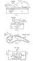
- FIG. 1 is a longitudinal schematic of a prior art film cooled wall
- FIG. 1 there is shown a wall 10 which is to be protected from a hot flowing gas represented by arrow 11.
- Arrow 12 represents a jet of cooling fluid such as air, the cooling fluid being injected into the hot flowing gas 11 from a plenum 14.
- the hot gas and the cooling gas blend or mix in the area 15 while in the region of 16 the cooling gas contacts the wall 10 to effect cooling thereof.
- An undesirable separation of the cooling gas from wall 10 occurs in the area 17 immediately downstream of a cooling passageway 13 which is of generally circular cross-section.
- FIG. 2 illustrates how a jet of cooling gas represented by arrow 12 interacts with a stream of hot flowing gas to form twin vortices 18 and 19. This interaction consumes a portion of the energy in the hot gas.
- FIG. 3 There is shown in FIG. 3 a hollow turbine blade wherein the interior serves as a plenum chamber 14.
- a jet of cooling gas 12 forms a coolant layer 21 which protects wall 10 of the turbine blade 20 from the hot gas 11.
- Passageway 13 has a height and width represented by double-ended arrows 22 and 23, respectively.
- passageway 13 is defined by a flat surface 24 which is contiguous with curved sidewall surfaces 25 and 26 which intersect to form a pointed member or cusp 27.
- a cusp is a pointed projection formed by or arising from the intersection of two arcs or foils.
- the pointed member 27 together with the arcs or curves 25 and 26 are considered as the cusp portion of the passageway 13 which has a flat surface 24 opposite the cusp.
- the flat surface 24 has a width delineated by the double ended arrow 28, which width is preferably less than the width 23 of passageway 13.
- pointed member 27 may hve its point blunted to preempt the inevitable progressive erosion which would occur to the point.
- the curved surfaces 25 and 26, as shown, have a constant curvature, that is, as portions of circles they have constant radii. It will be understood that this is not a requirement of the invention. Thus, the curvature of surfaces 25 and 26 may decrease in a downstream direction, that is, in the direction of the hot flowing gas 11.
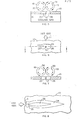
- the cusp portions 25, 26 and 27 are symmetrical to a plane perpendicular to the wall 10 and parallel to the flowing gas 11 and lying along the line 29.
- FIG. 5 which is a transverse sectional view taken along the line 5-5 of FIG. 4 shows vortices 18 and 19 generated by hot gas as illustrated in FIG. 2 with regard to the prior art.
- vortices 30 and 31 are formed in the cooling gas injected into the hot flowing gas through passageway 13 by flow passage geometry. Because of the vortices 30 and 31 developed in the injected jet of cooling gas, less energy is extracted from the hot flowing gas to establish vortices of a specific magnitude.
- FIG. 5 It should be noted in FIG. 5 that vortices 30 and 31 rotate in the same direction as their associated vortices 18 and 19, respectively, but are contra-rotating with respect to each other. This is because the cusp portion 25,26 and 27 of passageway 13 is upstream of the flat surface 24 with respect to the direction of flow of the hot gas 11.
- the configuration shown in FIG. 4 will be referred to as a top cusp.
- FIG. 6 a bottom cusp for passagewy 13 is shown in FIG. 6.
- the passageway 13 of FIG. 6 is simply reversed from that shown in FIG. 4 so that the cusp portions 25,26 and 27 are at the downstream side of passageway 13.
- FIG. 7, which is a view taken along the line 7-7 of FIG. 6, illustrates the result of using a bottom cusp configuration for the cooling passage 13.
- the arrows representing the vortices 18 and 19 are similar to the prior art vortices 18 and 19 shown in FIG. 2.
- the vortices produced in the jet of injected cooling fluid or gas because of the cusp configuration of the cooling passageway, rotate in directions opposite to their associated vordices 18 and 19, as illustrated by the arrows 32 and 33, respectively.
- the effect is to increase film cooling immediately downstream of the passageway 13 by preventing or minimizing flow separation of the cooling gas from the wall 10.
- FIG. 8 is a schematic plan view illustrating the increased surface area of cooling effected by using a top cusp passageway, as compared to the prior art circular passageway.
- the cusp shaped passageway 13 provides cooling for an area 34 for the wall 10.
- a circular passageway 35 of the same flow area provides cooling for a much smaller surface area 36. It will be understood that FIG. 8 is illustrative only and the passageways 13 and 35 as well as the cooled areas 34 and 36 are not drawn to any particular scale.
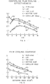
- curves 41,42 and 43 are plotted for relative film cooling coverage vs. isotherm area for a circular passageway, a bottom cusp and a top cusp, respectively, with same flow areas. As shown, both the bottom cusp and the top cusp are significantly better than the circular passageway with respect to the area cooled.
- the graphs of FIGS. 9 and 10 were derived at a blowing rate M * 1.23.
- the cooling passageways configured in accordance with the invention have been proven operative for any blowing rate from 0.2 to 2.1 which is the range normally used for film cooling of turbine blades and combustor walls.
- the invention is operative over any blowing rate attainable by presently known cooling fluids and hot gases and as defined by M on page 7.
- a film cooling passageway a portion of which in cross-section is shaped as a cusp, provides increased film cooling effectiveness. Additionally, if the cusp is on the downstream side of the passageway with respect to the hot flowing gas from which a wall is to be protected, separation of the cooling fluid from the wall immediately downstream of he passageway is substantially eliminated. It will be understood that changes and modifications may be made to the above described invention without departing from its spirit and scope, as set forth in the claims appended hereto.
Landscapes
- Engineering & Computer Science (AREA)
- Mechanical Engineering (AREA)
- General Engineering & Computer Science (AREA)
- Chemical & Material Sciences (AREA)
- Combustion & Propulsion (AREA)
- Turbine Rotor Nozzle Sealing (AREA)
- Chemical Vapour Deposition (AREA)
Applications Claiming Priority (2)
| Application Number | Priority Date | Filing Date | Title |
|---|---|---|---|
| US06/580,419 US4529358A (en) | 1984-02-15 | 1984-02-15 | Vortex generating flow passage design for increased film cooling effectiveness |
| US580419 | 1984-02-15 |
Publications (2)
| Publication Number | Publication Date |
|---|---|
| EP0151918A2 true EP0151918A2 (de) | 1985-08-21 |
| EP0151918A3 EP0151918A3 (de) | 1987-03-11 |
Family
ID=24321032
Family Applications (1)
| Application Number | Title | Priority Date | Filing Date |
|---|---|---|---|
| EP85100016A Withdrawn EP0151918A3 (de) | 1984-02-15 | 1985-01-02 | Verfahren und Anordnung zur Kühlung von Hochtemperaturbauten mit einem Fluidkühlmittel |
Country Status (5)
| Country | Link |
|---|---|
| US (1) | US4529358A (de) |
| EP (1) | EP0151918A3 (de) |
| JP (1) | JPS60216022A (de) |
| CA (1) | CA1225530A (de) |
| IL (1) | IL74050A0 (de) |
Cited By (2)
| Publication number | Priority date | Publication date | Assignee | Title |
|---|---|---|---|---|
| FR2735561A1 (fr) * | 1995-06-14 | 1996-12-20 | Snecma | Chambre de combustion comportant une paroi annulaire multiperforee |
| US10604269B2 (en) | 2016-03-03 | 2020-03-31 | Mitsubishi Aircraft Corporation | Structure for anti-adhesion of high-temperature air to airframe, and aircraft |
Families Citing this family (74)
| Publication number | Priority date | Publication date | Assignee | Title |
|---|---|---|---|---|
| US4669957A (en) * | 1985-12-23 | 1987-06-02 | United Technologies Corporation | Film coolant passage with swirl diffuser |
| US4773593A (en) * | 1987-05-04 | 1988-09-27 | United Technologies Corporation | Coolable thin metal sheet |
| US5083422A (en) * | 1988-03-25 | 1992-01-28 | General Electric Company | Method of breach cooling |
| US4916906A (en) * | 1988-03-25 | 1990-04-17 | General Electric Company | Breach-cooled structure |
| US4923371A (en) * | 1988-04-01 | 1990-05-08 | General Electric Company | Wall having cooling passage |
| US4848081A (en) * | 1988-05-31 | 1989-07-18 | United Technologies Corporation | Cooling means for augmentor liner |
| US5187937A (en) * | 1988-06-22 | 1993-02-23 | The Secretary Of State For Defence In Her Britannic Majesty's Government Of The United Kingdom Of Great Britain And Northern Ireland | Gas turbine engine combustors |
| US5299418A (en) * | 1992-06-09 | 1994-04-05 | Jack L. Kerrebrock | Evaporatively cooled internal combustion engine |
| JP2613560B2 (ja) * | 1994-05-31 | 1997-05-28 | 川崎重工業株式会社 | フィルム冷却式構造体 |
| EP0761928A3 (de) * | 1995-08-31 | 1999-03-31 | United Technologies Corporation | Kantenform zum Erleichtern von Wirbelstromprüfung |
| US6092982A (en) * | 1996-05-28 | 2000-07-25 | Kabushiki Kaisha Toshiba | Cooling system for a main body used in a gas stream |
| US6192670B1 (en) | 1999-06-15 | 2001-02-27 | Jack L. Kerrebrock | Radial flow turbine with internal evaporative blade cooling |
| US6254334B1 (en) | 1999-10-05 | 2001-07-03 | United Technologies Corporation | Method and apparatus for cooling a wall within a gas turbine engine |
| US6402470B1 (en) | 1999-10-05 | 2002-06-11 | United Technologies Corporation | Method and apparatus for cooling a wall within a gas turbine engine |
| DE10355108A1 (de) * | 2003-11-24 | 2005-06-02 | Alstom Technology Ltd | Verfahren zur Verbesserung der Strömungsverhältnisse in einem Axialkompressor sowie Axialkompressor zur Durchführung des Verfahrens |
| US7328580B2 (en) * | 2004-06-23 | 2008-02-12 | General Electric Company | Chevron film cooled wall |
| JP4898253B2 (ja) * | 2005-03-30 | 2012-03-14 | 三菱重工業株式会社 | ガスタービン用高温部材 |
| JP5039837B2 (ja) * | 2005-03-30 | 2012-10-03 | 三菱重工業株式会社 | ガスタービン用高温部材 |
| JP4752841B2 (ja) * | 2005-11-01 | 2011-08-17 | 株式会社Ihi | タービン部品 |
| US20080003096A1 (en) * | 2006-06-29 | 2008-01-03 | United Technologies Corporation | High coverage cooling hole shape |
| JP4941891B2 (ja) * | 2006-11-13 | 2012-05-30 | 株式会社Ihi | フィルム冷却構造 |
| US7670108B2 (en) * | 2006-11-21 | 2010-03-02 | Siemens Energy, Inc. | Air seal unit adapted to be positioned adjacent blade structure in a gas turbine |
| US20100034662A1 (en) * | 2006-12-26 | 2010-02-11 | General Electric Company | Cooled airfoil and method for making an airfoil having reduced trail edge slot flow |
| US20090304494A1 (en) * | 2008-06-06 | 2009-12-10 | United Technologies Corporation | Counter-vortex paired film cooling hole design |
| US8128366B2 (en) * | 2008-06-06 | 2012-03-06 | United Technologies Corporation | Counter-vortex film cooling hole design |
| GB0908540D0 (en) | 2009-05-19 | 2009-06-24 | Rolls Royce Plc | A gas turbine engine having a nacelle and a breather duct |
| US8371814B2 (en) * | 2009-06-24 | 2013-02-12 | Honeywell International Inc. | Turbine engine components |
| GB0919107D0 (en) * | 2009-11-02 | 2009-12-16 | Rolls Royce Plc | A boundary layer energiser |
| GB0919110D0 (en) * | 2009-11-02 | 2009-12-16 | Rolls Royce Plc | A boundary layer energiser |
| GB0919115D0 (en) * | 2009-11-02 | 2009-12-16 | Rolls Royce Plc | Breather duct shielding |
| US8529193B2 (en) * | 2009-11-25 | 2013-09-10 | Honeywell International Inc. | Gas turbine engine components with improved film cooling |
| JP4954309B2 (ja) | 2010-03-24 | 2012-06-13 | 川崎重工業株式会社 | ダブルジェット式フィルム冷却構造 |
| US8905713B2 (en) | 2010-05-28 | 2014-12-09 | General Electric Company | Articles which include chevron film cooling holes, and related processes |
| US8628293B2 (en) * | 2010-06-17 | 2014-01-14 | Honeywell International Inc. | Gas turbine engine components with cooling hole trenches |
| JP5982807B2 (ja) * | 2011-12-15 | 2016-08-31 | 株式会社Ihi | タービン翼 |
| US9482100B2 (en) | 2012-02-15 | 2016-11-01 | United Technologies Corporation | Multi-lobed cooling hole |
| US8689568B2 (en) | 2012-02-15 | 2014-04-08 | United Technologies Corporation | Cooling hole with thermo-mechanical fatigue resistance |
| US10422230B2 (en) | 2012-02-15 | 2019-09-24 | United Technologies Corporation | Cooling hole with curved metering section |
| US8522558B1 (en) | 2012-02-15 | 2013-09-03 | United Technologies Corporation | Multi-lobed cooling hole array |
| US9024226B2 (en) | 2012-02-15 | 2015-05-05 | United Technologies Corporation | EDM method for multi-lobed cooling hole |
| US9416665B2 (en) | 2012-02-15 | 2016-08-16 | United Technologies Corporation | Cooling hole with enhanced flow attachment |
| US9279330B2 (en) | 2012-02-15 | 2016-03-08 | United Technologies Corporation | Gas turbine engine component with converging/diverging cooling passage |
| US9422815B2 (en) | 2012-02-15 | 2016-08-23 | United Technologies Corporation | Gas turbine engine component with compound cusp cooling configuration |
| US8850828B2 (en) | 2012-02-15 | 2014-10-07 | United Technologies Corporation | Cooling hole with curved metering section |
| US9284844B2 (en) | 2012-02-15 | 2016-03-15 | United Technologies Corporation | Gas turbine engine component with cusped cooling hole |
| US9410435B2 (en) | 2012-02-15 | 2016-08-09 | United Technologies Corporation | Gas turbine engine component with diffusive cooling hole |
| US8584470B2 (en) | 2012-02-15 | 2013-11-19 | United Technologies Corporation | Tri-lobed cooling hole and method of manufacture |
| US9598979B2 (en) | 2012-02-15 | 2017-03-21 | United Technologies Corporation | Manufacturing methods for multi-lobed cooling holes |
| US8683814B2 (en) | 2012-02-15 | 2014-04-01 | United Technologies Corporation | Gas turbine engine component with impingement and lobed cooling hole |
| US8763402B2 (en) | 2012-02-15 | 2014-07-01 | United Technologies Corporation | Multi-lobed cooling hole and method of manufacture |
| US8733111B2 (en) | 2012-02-15 | 2014-05-27 | United Technologies Corporation | Cooling hole with asymmetric diffuser |
| US8707713B2 (en) | 2012-02-15 | 2014-04-29 | United Technologies Corporation | Cooling hole with crenellation features |
| US9416971B2 (en) | 2012-02-15 | 2016-08-16 | United Technologies Corporation | Multiple diffusing cooling hole |
| US9273560B2 (en) | 2012-02-15 | 2016-03-01 | United Technologies Corporation | Gas turbine engine component with multi-lobed cooling hole |
| US8572983B2 (en) | 2012-02-15 | 2013-11-05 | United Technologies Corporation | Gas turbine engine component with impingement and diffusive cooling |
| US8683813B2 (en) | 2012-02-15 | 2014-04-01 | United Technologies Corporation | Multi-lobed cooling hole and method of manufacture |
| US9650900B2 (en) | 2012-05-07 | 2017-05-16 | Honeywell International Inc. | Gas turbine engine components with film cooling holes having cylindrical to multi-lobe configurations |
| US10113433B2 (en) | 2012-10-04 | 2018-10-30 | Honeywell International Inc. | Gas turbine engine components with lateral and forward sweep film cooling holes |
| EP2961964B1 (de) * | 2013-02-26 | 2020-10-21 | United Technologies Corporation | Bauteil eines gasturbinentriebwerks und zugehöriges verfahren zur herstellung einer öffnung |
| US10378362B2 (en) | 2013-03-15 | 2019-08-13 | United Technologies Corporation | Gas turbine engine component cooling channels |
| US20150003962A1 (en) * | 2013-06-27 | 2015-01-01 | Bruce L. Smith | Apparatus for reducing a temperature gradient of mainstream fluid downstream of an airfoil in a gas turbine engine |
| US9599017B2 (en) * | 2013-06-28 | 2017-03-21 | General Electric Company | Gas turbine engine and method of operating thereof |
| EP3967854B1 (de) * | 2013-11-25 | 2023-07-05 | Raytheon Technologies Corporation | Anordnung für ein turbinentriebwerk |
| US20160177733A1 (en) * | 2014-04-25 | 2016-06-23 | United Technologies Corporation | Method of forming cooling holes |
| CN104033251A (zh) * | 2014-06-12 | 2014-09-10 | 中国科学院工程热物理研究所 | 一种提高燃机高温部件冷却效率的气膜孔结构 |
| US11021965B2 (en) | 2016-05-19 | 2021-06-01 | Honeywell International Inc. | Engine components with cooling holes having tailored metering and diffuser portions |
| US10605092B2 (en) | 2016-07-11 | 2020-03-31 | United Technologies Corporation | Cooling hole with shaped meter |
| US10767489B2 (en) * | 2016-08-16 | 2020-09-08 | General Electric Company | Component for a turbine engine with a hole |
| US10539026B2 (en) | 2017-09-21 | 2020-01-21 | United Technologies Corporation | Gas turbine engine component with cooling holes having variable roughness |
| US10590779B2 (en) | 2017-12-05 | 2020-03-17 | United Technologies Corporation | Double wall turbine gas turbine engine blade cooling configuration |
| US10648342B2 (en) | 2017-12-18 | 2020-05-12 | General Electric Company | Engine component with cooling hole |
| US11339667B2 (en) | 2020-08-11 | 2022-05-24 | Raytheon Technologies Corporation | Cooling arrangement including overlapping diffusers |
| WO2023211485A2 (en) * | 2021-10-22 | 2023-11-02 | Raytheon Technologies Corporation | Gas turbine engine article with cooling holes for mitigating recession |
| CN120003732B (zh) * | 2025-04-21 | 2025-07-18 | 中国人民解放军国防科技大学 | 含可设计性微通道的高速飞行器尖锐前缘主动冷却结构 |
Family Cites Families (17)
| Publication number | Priority date | Publication date | Assignee | Title |
|---|---|---|---|---|
| US14072A (en) * | 1856-01-08 | Machine for sawing marble obelisks | ||
| US1597885A (en) * | 1922-10-19 | 1926-08-31 | Mccord Radiator & Mfg Co | Radiator core |
| US2058057A (en) * | 1931-05-08 | 1936-10-20 | Hohlfelder Company | Radiator |
| GB1183714A (en) * | 1966-02-22 | 1970-03-11 | Hawker Siddeley Aviation Ltd | Improvements in or relating to Boundary Layer Control Systems. |
| GB1152331A (en) * | 1966-05-18 | 1969-05-14 | Rolls Royce | Improvements in Gas Turbine Blade Cooling |
| US3542486A (en) * | 1968-09-27 | 1970-11-24 | Gen Electric | Film cooling of structural members in gas turbine engines |
| US3606572A (en) * | 1969-08-25 | 1971-09-20 | Gen Motors Corp | Airfoil with porous leading edge |
| US3698834A (en) * | 1969-11-24 | 1972-10-17 | Gen Motors Corp | Transpiration cooling |
| GB1285369A (en) * | 1969-12-16 | 1972-08-16 | Rolls Royce | Improvements in or relating to blades for fluid flow machines |
| FR2155835B1 (de) * | 1971-10-08 | 1974-05-31 | Snecma | |
| US3891348A (en) * | 1972-04-24 | 1975-06-24 | Gen Electric | Turbine blade with increased film cooling |
| US3796258A (en) * | 1972-10-02 | 1974-03-12 | Dunham Bush Inc | High capacity finned tube heat exchanger |
| US3826082A (en) * | 1973-03-30 | 1974-07-30 | Gen Electric | Combustion liner cooling slot stabilizing dimple |
| US4221539A (en) * | 1977-04-20 | 1980-09-09 | The Garrett Corporation | Laminated airfoil and method for turbomachinery |
| US4376004A (en) * | 1979-01-16 | 1983-03-08 | Westinghouse Electric Corp. | Method of manufacturing a transpiration cooled ceramic blade for a gas turbine |
| JPS55109703A (en) * | 1979-02-19 | 1980-08-23 | Hitachi Ltd | Gas-turbine blade capable of being cooled |
| US4384823A (en) * | 1980-10-27 | 1983-05-24 | The United States Of America As Represented By The Administrator Of The National Aeronautics And Space Administration | Curved film cooling admission tube |
-
1984
- 1984-02-15 US US06/580,419 patent/US4529358A/en not_active Expired - Fee Related
- 1984-12-20 CA CA000470725A patent/CA1225530A/en not_active Expired
-
1985
- 1985-01-02 EP EP85100016A patent/EP0151918A3/de not_active Withdrawn
- 1985-01-14 IL IL74050A patent/IL74050A0/xx unknown
- 1985-02-14 JP JP60028139A patent/JPS60216022A/ja active Granted
Cited By (4)
| Publication number | Priority date | Publication date | Assignee | Title |
|---|---|---|---|---|
| FR2735561A1 (fr) * | 1995-06-14 | 1996-12-20 | Snecma | Chambre de combustion comportant une paroi annulaire multiperforee |
| EP0752560A1 (de) * | 1995-06-14 | 1997-01-08 | SOCIETE NATIONALE D'ETUDE ET DE CONSTRUCTION DE MOTEURS D'AVIATION -Snecma | Brennkammerwand mit einer grossen Anzahl versetzter Kühlungsschlitze |
| US5713207A (en) * | 1995-06-14 | 1998-02-03 | Societe National D'etude Et De Construction De Moteurs D'aviation S.N.E.C.M.A. | Annular combustion chamber with a perforated wall |
| US10604269B2 (en) | 2016-03-03 | 2020-03-31 | Mitsubishi Aircraft Corporation | Structure for anti-adhesion of high-temperature air to airframe, and aircraft |
Also Published As
| Publication number | Publication date |
|---|---|
| JPH025883B2 (de) | 1990-02-06 |
| IL74050A0 (en) | 1985-04-30 |
| US4529358A (en) | 1985-07-16 |
| CA1225530A (en) | 1987-08-18 |
| EP0151918A3 (de) | 1987-03-11 |
| JPS60216022A (ja) | 1985-10-29 |
Similar Documents
| Publication | Publication Date | Title |
|---|---|---|
| US4529358A (en) | Vortex generating flow passage design for increased film cooling effectiveness | |
| US5382133A (en) | High coverage shaped diffuser film hole for thin walls | |
| US5660525A (en) | Film cooled slotted wall | |
| US5651662A (en) | Film cooled wall | |
| CN86108821A (zh) | 具有涡流扩散器的薄膜冷却剂通道 | |
| US6241468B1 (en) | Coolant passages for gas turbine components | |
| EP0774047B1 (de) | Turbinenschaufel mit stegen in der austrittskaufe, die als diffusoren wirken | |
| US6514042B2 (en) | Method and apparatus for cooling a wall within a gas turbine engine | |
| US4601638A (en) | Airfoil trailing edge cooling arrangement | |
| CN1006167B (zh) | 中空铸造叶片薄膜冷却通道 | |
| CN1097139C (zh) | 用于翼型的冷却结构 | |
| JP2855430B2 (ja) | 流体ダイナミツクポンプ | |
| JP4094010B2 (ja) | 扇形後縁涙滴配列 | |
| US7997868B1 (en) | Film cooling hole for turbine airfoil | |
| US5281084A (en) | Curved film cooling holes for gas turbine engine vanes | |
| CA1273583A (en) | Coolant passages with full coverage film cooling slot | |
| JPH07103806B2 (ja) | エ−ロフオイルの冷却される壁 | |
| JPH07103801B2 (ja) | エ−ロフオイルの冷却される壁 | |
| JPH0571302A (ja) | タービン翼形部のフイルム冷却構造 | |
| JP2001501703A (ja) | ガスタービンのエアフォイルの冷却 | |
| JPS6237201B2 (de) | ||
| JP2002364305A (ja) | タービンエンジン用の冷却可能なブレードまたはベーン | |
| JP2006242187A (ja) | タービンのエーロフォイル | |
| JPH07189603A (ja) | タービン冷却翼及び冷却部材 | |
| US11346248B2 (en) | Turbine nozzle segment and a turbine nozzle comprising such a turbine nozzle segment |
Legal Events
| Date | Code | Title | Description |
|---|---|---|---|
| PUAI | Public reference made under article 153(3) epc to a published international application that has entered the european phase |
Free format text: ORIGINAL CODE: 0009012 |
|
| AK | Designated contracting states |
Designated state(s): BE CH DE FR GB IT LI NL SE |
|
| PUAL | Search report despatched |
Free format text: ORIGINAL CODE: 0009013 |
|
| AK | Designated contracting states |
Kind code of ref document: A3 Designated state(s): BE CH DE FR GB IT LI NL SE |
|
| 17P | Request for examination filed |
Effective date: 19870821 |
|
| 17Q | First examination report despatched |
Effective date: 19880212 |
|
| STAA | Information on the status of an ep patent application or granted ep patent |
Free format text: STATUS: THE APPLICATION IS DEEMED TO BE WITHDRAWN |
|
| 18D | Application deemed to be withdrawn |
Effective date: 19880623 |
|
| RIN1 | Information on inventor provided before grant (corrected) |
Inventor name: PAPELL, SOLOMAN STEPHEN |