EP0152121A2 - Wärmepumpe mit mehrstufigem Verdichter - Google Patents
Wärmepumpe mit mehrstufigem Verdichter Download PDFInfo
- Publication number
- EP0152121A2 EP0152121A2 EP85102539A EP85102539A EP0152121A2 EP 0152121 A2 EP0152121 A2 EP 0152121A2 EP 85102539 A EP85102539 A EP 85102539A EP 85102539 A EP85102539 A EP 85102539A EP 0152121 A2 EP0152121 A2 EP 0152121A2
- Authority
- EP
- European Patent Office
- Prior art keywords
- compressor
- engine
- engine speed
- heat pump
- control
- Prior art date
- Legal status (The legal status is an assumption and is not a legal conclusion. Google has not performed a legal analysis and makes no representation as to the accuracy of the status listed.)
- Withdrawn
Links
Images



Classifications
-
- F—MECHANICAL ENGINEERING; LIGHTING; HEATING; WEAPONS; BLASTING
- F02—COMBUSTION ENGINES; HOT-GAS OR COMBUSTION-PRODUCT ENGINE PLANTS
- F02G—HOT GAS OR COMBUSTION-PRODUCT POSITIVE-DISPLACEMENT ENGINE PLANTS; USE OF WASTE HEAT OF COMBUSTION ENGINES; NOT OTHERWISE PROVIDED FOR
- F02G5/00—Profiting from waste heat of combustion engines, not otherwise provided for
-
- F—MECHANICAL ENGINEERING; LIGHTING; HEATING; WEAPONS; BLASTING
- F25—REFRIGERATION OR COOLING; COMBINED HEATING AND REFRIGERATION SYSTEMS; HEAT PUMP SYSTEMS; MANUFACTURE OR STORAGE OF ICE; LIQUEFACTION SOLIDIFICATION OF GASES
- F25B—REFRIGERATION MACHINES, PLANTS OR SYSTEMS; COMBINED HEATING AND REFRIGERATION SYSTEMS; HEAT PUMP SYSTEMS
- F25B27/00—Machines, plants or systems, using particular sources of energy
-
- F—MECHANICAL ENGINEERING; LIGHTING; HEATING; WEAPONS; BLASTING
- F25—REFRIGERATION OR COOLING; COMBINED HEATING AND REFRIGERATION SYSTEMS; HEAT PUMP SYSTEMS; MANUFACTURE OR STORAGE OF ICE; LIQUEFACTION SOLIDIFICATION OF GASES
- F25B—REFRIGERATION MACHINES, PLANTS OR SYSTEMS; COMBINED HEATING AND REFRIGERATION SYSTEMS; HEAT PUMP SYSTEMS
- F25B30/00—Heat pumps
- F25B30/02—Heat pumps of the compression type
-
- F—MECHANICAL ENGINEERING; LIGHTING; HEATING; WEAPONS; BLASTING
- F25—REFRIGERATION OR COOLING; COMBINED HEATING AND REFRIGERATION SYSTEMS; HEAT PUMP SYSTEMS; MANUFACTURE OR STORAGE OF ICE; LIQUEFACTION SOLIDIFICATION OF GASES
- F25B—REFRIGERATION MACHINES, PLANTS OR SYSTEMS; COMBINED HEATING AND REFRIGERATION SYSTEMS; HEAT PUMP SYSTEMS
- F25B2400/00—Component parts or details not otherwise provided for in this subclass
- F25B2400/07—Details of compressors or related parts
- F25B2400/075—Details of compressors or related parts with parallel compressors
-
- F—MECHANICAL ENGINEERING; LIGHTING; HEATING; WEAPONS; BLASTING
- F25—REFRIGERATION OR COOLING; COMBINED HEATING AND REFRIGERATION SYSTEMS; HEAT PUMP SYSTEMS; MANUFACTURE OR STORAGE OF ICE; LIQUEFACTION SOLIDIFICATION OF GASES
- F25B—REFRIGERATION MACHINES, PLANTS OR SYSTEMS; COMBINED HEATING AND REFRIGERATION SYSTEMS; HEAT PUMP SYSTEMS
- F25B2600/00—Control issues
- F25B2600/02—Compressor control
- F25B2600/026—Compressor control by controlling unloaders
-
- Y—GENERAL TAGGING OF NEW TECHNOLOGICAL DEVELOPMENTS; GENERAL TAGGING OF CROSS-SECTIONAL TECHNOLOGIES SPANNING OVER SEVERAL SECTIONS OF THE IPC; TECHNICAL SUBJECTS COVERED BY FORMER USPC CROSS-REFERENCE ART COLLECTIONS [XRACs] AND DIGESTS
- Y02—TECHNOLOGIES OR APPLICATIONS FOR MITIGATION OR ADAPTATION AGAINST CLIMATE CHANGE
- Y02B—CLIMATE CHANGE MITIGATION TECHNOLOGIES RELATED TO BUILDINGS, e.g. HOUSING, HOUSE APPLIANCES OR RELATED END-USER APPLICATIONS
- Y02B30/00—Energy efficient heating, ventilation or air conditioning [HVAC]
- Y02B30/52—Heat recovery pumps, i.e. heat pump based systems or units able to transfer the thermal energy from one area of the premises or part of the facilities to a different one, improving the overall efficiency
-
- Y—GENERAL TAGGING OF NEW TECHNOLOGICAL DEVELOPMENTS; GENERAL TAGGING OF CROSS-SECTIONAL TECHNOLOGIES SPANNING OVER SEVERAL SECTIONS OF THE IPC; TECHNICAL SUBJECTS COVERED BY FORMER USPC CROSS-REFERENCE ART COLLECTIONS [XRACs] AND DIGESTS
- Y02—TECHNOLOGIES OR APPLICATIONS FOR MITIGATION OR ADAPTATION AGAINST CLIMATE CHANGE
- Y02T—CLIMATE CHANGE MITIGATION TECHNOLOGIES RELATED TO TRANSPORTATION
- Y02T10/00—Road transport of goods or passengers
- Y02T10/10—Internal combustion engine [ICE] based vehicles
- Y02T10/12—Improving ICE efficiencies
Definitions
- This invention relates to heat pumps and more especially to a self-contained fossil-fueled, air to water, heat pump which is capable of extracting energy from air and supplying this energy to heat hot water for space heating purposes.
- a particular exemplary use of the heat pump system of the present invention is for maintaining temperature within a glasshouse with the glasshouse being provided with a hot water pipe heating system supplied with hot water from the heat pump system. Air is extracted from the space in the glasshouse when its humidity rises to too high a value with the heat pump system extracting latent heat from this removed humid air for supply to the heating water.
- a heat pump apparatus comprising a refrigerant compressor having a number of stages which can be loaded or unloaded responsive to varying compressor demand, characterised by a variable speed engine for driving the compressor, and a control circuit arranged to sense the compressor load and to control the engine speed so as to increase and decrease over a range as the compressor load increases and decreases over a corresponding range.
- the compressor cylinders either will be fully unloaded so as to maintain the starting torque at a minimum value or there will be provided a disconnectable clutch between the engine and the compressor to ensure that the compressor is not driven during the start up.
- the first stage in the unloading of the heat pump circuit is controlled modulation of the compressor speed to a predetermined minimum value which may, for example, be approximately 70% of the maximum speed i.e. a 30% heat capacity reduction.
- control can then be achieved by sequenced unloading of the compressor cylinders.
- the modulation of the engine speed may be repeated for one or more further stages of compressor loading or unloading as the compressor demand increases or decreases - this is more fully discussed below.
- Preferably means are provided whereby with a rising demand for a heat requirement beyond the capability of the selected heat pump system an initiation signal is made to start operation of an additional bivalent heat sourceand/or a warning signal is provided.
- the whole unit assembly is preferably totally self-contained with an electrical generator being included driven by the internal combustion engine. This electrical supply is then used to power evaporator fan motors and other power driven means in the system as well as any illumination device that may be required.
- the fundamental control circuitry is preferably powered by a battery circuit such that the operating sequence control is available when the engine is not running. Whereas the same battery may be used to supply the necessaryy energy to restart the engine preferably two batteries are provided, one a light duty battery for ensuring operation of the control circuitry and the other a heavy duty battery for supplying heavier currents when required, for example for starting the engine.
- the speed of the engine controlled so that it varies across an operating range so that the engine speed increases or decreases as the compressor load increases or decreases, suitably in an infinitely variable manner so that the engine goes just fast enough to accommodate the desired compressor load.
- the compressor has a number of stages which may brought on line or taken off line in a step-wise fashion as the compressor load increases or decreases
- the engine speeds modulation may be used, as it were, to "fill in” the gaps between these step wise changes in the number of compressor stages in operation.
- an increase in compressor load may make it appropriate to increase the number of compressor stages on line.
- the engine speed is at the bottom end of its range.
- the control circuit may be arranged to derive a signal representing compressor demand, to produce therefrom a demanded engine speed signal which is modified in accordance with the number of stages loaded or unloaded and to thereby control the engine throttle setting so that with changing compressor demand, following a change in the number of compressor stages in operation, the engine speed varies across its range.
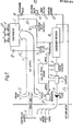
- FIG. 1 there is illustrated a heat pump system adapted for the extraction of ambient energy from either outside air or from a mixture of outside air and process air, preferably having a surplus high humidity content, and using this energy for space heating by way of a hot water supply.
- a particular example has been for heating a glasshouse where air extracted from the glasshouse is used to give up its excess heat for supply to the heat pump for subsequently heating a hot water supply to heating pipes in the interior of the greenhouse.
- the housing is shown as having three air inlets, an air inlet 4 provided with a controllable damper for controlling the flow of air from the interior of the space to be heated, and two fresh air inlets 5 provided with self-compensating pressure relief dampers.
- the air supply 1 passes over the various components of the heat pump system before passing to an evaporator 2 through which the air supply is drawn by means of fans 22 driven by motors 3. With this arrangement the amount of input fresh air is automatically increased when the control damper 4 is closed and is reduced when the control damper is opened.
- the heat pump system components comprise, inter alia, a fossil-fuel, preferably gas or diesel, engine 6, connected via a magnetic clutch drive 30 to a refrigerant compressor 7.
- the engine exhaust and coolant liquid in the engine pass respectively through heat exchangers 8 and 9.
- a generator 31 is preferably included to make the control system self-contained as will be explained later although a purely external electrical supply may be relied upon should such be more convenient in a particular location of the system of the invention. While the magnetic clutch drive 30 is preferred a direct resilient coupling may be used if desired although in such a case it will be necessary to ensure that the cylinders of the compressor 7 are unloaded during start up of the engine 6 rather than simply declutching the compressor from the engine during the start up.
- the refrigerant system comprises an evaporator 2 from which refrigerant passes through a suction line or pipe 34 to the compressor 7.
- a temperature sensor 32 In the pipe 34 there is provided a temperature sensor 32.
- the refrigerant passes from the compressor 7 to a condenser receiver 10 where it is condensed into a cooled liquid. This liquid then passes through a filter drier 12, a sight glass 13, and a shut-off solenoid valve 14 to an automatic thermostatic expansion valve 15 through which it is expanded back into the evaporator 2.
- a hot gas by-pass pipe 33 leads from the compressor directly back to the evaporator with fluid flow there-through being controlled by a by-pass solenoid valve 16.
- the automatically controlled hot gas defrost control is such that at pre-selected periods it will monitor the prevailing temperature in the line of 34 and when that temperature has dropped to 2 C the valve 16 will be opened to initiate defrost with the defrosting operation being stopped once the sensed temperature in line 34 has risen to 6 C.
- the flow of water to be heated by the heat pump system is fed into the housing of the system via a return water conduit 27 which leads to the condenser receiver 10.
- the water passes through the condenser 10 being heated by heat exchange with the hot refrigerant gas therein to condense the gas into liquid.
- the water passes on to the coolant heat exchanger 9 and the exhaust heat exchanger 8 before passing through a water pump 11 to the supply conduit leading to the space to be heated.
- the air supply 1 passes over the various engine, compressor and heat exchange components of the heat pump system to recover available residual radiant heat therefrom prior to being passed through the evaporator 2 and thence being exhausted to the atmosphere.
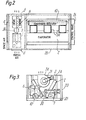
- FIG. 2 illustrates the heat pump system in plan view with the various components of the heat system being mounted as a self-containing unit on a transportable base 35 ( Figure 3).
- a housing 20 is mounted on the base 35 to enclose the components of the system, a control panel 26 being mounted at one end of the housing with the controllable damper inlet 4 for space air being provided at the other end of the housing.
- the automatic damper inlets 5 are shown at either side of the housing.
- a magnetic clutch drive 30 is provided betwen the motor 6 and the compressor 7.
- the evaporator 2 can be seen as comprising two heat exchange coils arranged in substantially V-formation with the space across the top of the V being closed by a panel 25.
- Inlets to fans 22 communicate with the space within the V-shape defined by the evaporator with the fan being driven by a motor 3 via a drive belt 21 to extract air from the space downstream of the evaporator 2 for expulsion through an air outlet 24 to the atmosphere.
- Three air outlet fans are shown in the drawings although it will be appreciated that the number of fans used will depend upon the size and arrangement of any particular installation.
- FIG 5 diagrammatically illustrates the control system for the heat pump above described and is for a preferred construction having the electrical generator 31 driven by the engine 6.
- Two batteries are connected to be charged by the generator, one being a heavy duty battery 40 for supplying power for starting the engine and to those parts of the system which require a substantial quantity of energy during operation and the other being a lighter duty battery 41 connected to control logic circuitry illustrated by block 19 of Figure 5.
- a bus 45 is shown connected to the heavy duty battery 40 and connected to the bus 45 are a return supply line to the engine 6 and connections for supplying power to the water pump 11, the magnetic clutch 30, the fans 3 and the damper 4.
- the water pump, clutch, fans and damper are also shown all connected individually to the control circuit 19 in that operation of these members will be controlled by the circuit 19 but be powered fromthe bus 45. Also shown as being controlled by the circuit 19 is a compressor unload control 42, the defrost solenoid 16 and the solenoid valve 14. Inputs to the control circuits 19 are provided by a relative humidity sensor 51 and a dry bulb temperature sensor 50, both of which will be within the space from which humid air will be extracted through the control damper 4, and the temperature sensor 32 in the conduit 31 leading from the evaporator to the compressor.
- the humidity of the air in the space will be checked by the circuitry with the dampers 4 being controlled to allow an increased flow of air from the space when its humidity has increased to too high a value.
- fresh air through the inlets 5 will be blended with the air from the space with heat being extracted from the air so that it passes through the evaporator 2 for recovery in the condenser receiver to heat the water being passed on for space heating purposes.
- control circuit initially will control the engine throttle mechanism to slow it to approximately 70% of its normal desired output speed. If over-heating still occurs then the control circuitry will actuate compressor unload control 42 which will, in turn, unload the compressor cylinders until the required balance is achieved.
- the control circuitry will automatically switch off the engine and return the system to its standby condition awaiting sufficient drop in temperature in the space being controlled for the engine to be switched on once again to restart the heating operation unless the engine is required to carry on running for electrical generation purposes, when the magnetic clutch mechanism will be disengaged.
- the defrost sequence can either be initiated and terminated in dependence upon the sensing of lower and upper temperatures in a range as described previously, or may be initiated and terminated by means of a timer within the circuitry 19 the operation of which is triggered by the temperature sensed at 32 dropping below a pre-determined level.
- Lighting means for the installation can also be powered from the generator 31 and conveniently the lighting will only be operable at full power under control of the circuitry 19 when the generator is being driven with stand-by lighting only being provided from the battery when the engine is not driving the generator.
- Means can be provided whereby with the magnetic clutch being de-energised so that there is no longer any drive to the compressor, the engine can continue to operate to drive the generator for battery charging or other power generation purposes.
- the circuitry 19 can also be arranged to operate a warning device 60, or automatically to switch on some additional heating means, when the temperature in the space being controlled is not maintained despite the engine working at maximum speed with all cylinders of the compressor operating.
- a temperature sensor may be placed in the return conduit 27. Accordingly once the system is in operation the speed of the engine and the number of cylinders of the compressor unloaded will depend on the temperature sensed in the return water whereas, as before, the initial switching on of the system will depend on the dry bulb temperature sensed in the space to be controlled, the dampers 4 being controlled in dependence upon the humidity.
- Figures 9a to 9c show a second embodiment of the first aspect of the invention in which the system components have been rearranged so that the air is blown through the two evaporator sections 2a and 2b, rather than being sucked as in Figures 1 to 4 so that the ducting required when air is being sucked through is eliminated.
- the embodiment is otherwise similar to Figures 1 to 4.
- FIGs 6a to 8 illustrate heat pump apparatus according to the present invention. This will be described here in the context of its application to the heat pump system of Figures 1 to 5 but it will be appreciated that the heat pump apparatus of Figures 6a to 8 is not limited to that application and may be used in any suitable heat pump system.
- the heat pump apparatus comprises the gas or diesel engine 6, a multi-stage compressor 7 and a control circuit 61 which may, in the application of the invention to the heat pump systems of Figures 1 to 5, constitute a module of the control circuitry of Figure 5.
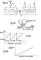
- the control circuit 61 is used to derive a signal used to operate an electro-mechanically actuated throttle valve 62 which controls the fuel delivered to the engine, the engine being under closed loop control of its operating speed by use of a conventional negative feedback loop, as illustrated in Figure 6b, in which the demanded engine speed, derived from the various input parameters which determine the compressor load and the actual engine speed derived from a tachometer 63 are combined to produce an actuating signal for the control valve 62.
- the tachometer 63 may be of any suitable type, for example using an optical or magnetic pulse pickup.
- the control circuitry 61 also controls actuators which determine the number of stages of the compressor which are on line at any one time. It co-ordinates the response of the compressor and engine, in terms of the engine speed and number of stages on line, in dependence upon the compressor load demand as shown in Figure 7a.
- the engine 6 is first started up and then run in accordance with a demanded speed signal from the control circuit 61 at its minimum normal operating speed, which might typically be 1200 rpm. At this stage, the first stage of the compressor is brought on-line.
- the compressor cylinders may be organised in three stages of two cylinders each, although, of course, the cylinders could alternatively be used as individual stages or there could be a different number of cylinders in each stage, dependent on considerations of system efficiency and prime energy usage.
- the demanded speed, and hence the actual speed, of the engine is increased in an infinite variable manner until the maximum normal engine speed, typically 1800 rpm, is reached. Then the control circuit delivers a signal to the compressor to bring the second compressor stage onto line, and, once this has been done, it reduces the engine demanded speed back to 1200 rpm. Then, for increasing compressor load demand, the engine speed is increased up to 1800 rpm again and then a similar transition occurs as the third stage is brought onto line.
- the net result is that at least in principle, there is a linear relationship between the compressor load demands and the compressor output as shown in Figure 7b.
- FIG. 8 shows in more detail the control circuit 61.
- the implementation shown is analog although it will be appreciated that an all-digital or an analog/digital hybrid could be used instead.
- An integrating demand controller 81 receives input signals such as sensed temperature, sensed relative humidity refrigerant head pressure, etc, and - produces an infinitely variable output signal representative of the compressor load demand. This signal is applied both to a pair of engine speed segment controllers 82 and 83 and a compressor step controller 84. In the latter, the output of the integrating demand controller 81 is compared by means of analog comparators with reference voltages representing the compressor load levels at which initiation of the first, second and third compressor stages, respectively is desired.
- the segment controller 82 contains two similar sections which operate in a similar manner to one another over different input (and output) voltage bands.
- the first section contains a level comparator monitoring the input voltage and an analogue switch (or relay) which is closed to deliver an output voltage varying linearly (optionally with an adjustable slope) with the input when the level comparator detects an input of at least 6 volts.
- the second section of segment controller 82 operates in a similar fashion with a comparator threshold of 10 volts.
- the segment controller 83 contains a similar section with a comparator threshold of 14 volts and a reference voltage source producing a voltage of, say, 6 volts defining the minimum desired engine speed.
- the three varying outputs from the segment controllers 82, 83 are connected to the input of the linear inversion controller 85, by means of normally open and normally closed contracts Rl/2 R2/2 R2/3 R3/2 and R3/3, which select one of these three voltages for application to the inversion controller 85 to produce the engine demand speed output.
- the inversion controller 85 resets the ramp shown in Figure 7a at each compressor stage transition by a stepped voltage corresponding to substracting 600 rpm from the demanded engine speed at the transition on the first to the second compressor stage and then again from the second to the third stage by comparison of its input with reference voltages corresponding to the stage transitions.
- the second, reference output from the controller 83 is connected in an analog wired-OR fashion with the other three outputs from the controllers 82 and 83 so that a minimum voltage of 6 volts is always applied to the input of the controller 85. This is to keep the engine running at its minimum speed under no load conditions.
- the inversion controller 85 scales the resulting signal so that the demanded engine speed signal varies in the range 10 to 0 volts, 10 volts representing the minimum speed and 0 volts representing the maximum, so that overspeed conditions which might be caused by an excess input voltage in a fault condition are unhibited.
- the upper voltages of the ranges of the outputs of the varying sections of controller 82 are determined by the opening of contracts R2/3 and R3/3 as determined by the step controller 84.
Landscapes
- Engineering & Computer Science (AREA)
- Mechanical Engineering (AREA)
- General Engineering & Computer Science (AREA)
- Physics & Mathematics (AREA)
- Thermal Sciences (AREA)
- Chemical & Material Sciences (AREA)
- Combustion & Propulsion (AREA)
- Control Of Vehicle Engines Or Engines For Specific Uses (AREA)
- Other Air-Conditioning Systems (AREA)
- Structures Of Non-Positive Displacement Pumps (AREA)
Applications Claiming Priority (2)
| Application Number | Priority Date | Filing Date | Title |
|---|---|---|---|
| GB8120469 | 1981-07-02 | ||
| GB8120469 | 1981-07-02 |
Related Parent Applications (2)
| Application Number | Title | Priority Date | Filing Date |
|---|---|---|---|
| EP82303497.0 Division | 1982-07-02 | ||
| EP82303497A Division EP0069564A3 (de) | 1981-07-02 | 1982-07-02 | Wärmepumpenanlage |
Publications (2)
| Publication Number | Publication Date |
|---|---|
| EP0152121A2 true EP0152121A2 (de) | 1985-08-21 |
| EP0152121A3 EP0152121A3 (de) | 1986-08-06 |
Family
ID=10522969
Family Applications (2)
| Application Number | Title | Priority Date | Filing Date |
|---|---|---|---|
| EP82303497A Withdrawn EP0069564A3 (de) | 1981-07-02 | 1982-07-02 | Wärmepumpenanlage |
| EP85102539A Withdrawn EP0152121A3 (de) | 1981-07-02 | 1982-07-02 | Wärmepumpe mit mehrstufigem Verdichter |
Family Applications Before (1)
| Application Number | Title | Priority Date | Filing Date |
|---|---|---|---|
| EP82303497A Withdrawn EP0069564A3 (de) | 1981-07-02 | 1982-07-02 | Wärmepumpenanlage |
Country Status (1)
| Country | Link |
|---|---|
| EP (2) | EP0069564A3 (de) |
Cited By (7)
| Publication number | Priority date | Publication date | Assignee | Title |
|---|---|---|---|---|
| WO1993011354A1 (en) * | 1991-11-28 | 1993-06-10 | I. Krüger Systems As | Method for utilization of heat energy in a district heating network from a generating plant with an air-cooled generator powered by an internal combustion engine, and a generating plant performing the method |
| WO1994009327A1 (de) * | 1992-10-12 | 1994-04-28 | Icemaster Gmbh | Steuerbare antriebseinheit mit verbrennungsmotor und generator |
| CN102175476A (zh) * | 2011-03-17 | 2011-09-07 | 上海理工大学 | 新风热回收实验系统 |
| US20130145762A1 (en) * | 2010-04-27 | 2013-06-13 | Ekkehard Laqua | Coupling system for a hybrid energy plant |
| EP2510286A4 (de) * | 2009-12-08 | 2014-07-09 | Electromotion Energy Corp | Ökosystem mit synergistischer energie |
| WO2016075384A1 (fr) * | 2014-11-14 | 2016-05-19 | Solaronics Chauffage | Procede de recuperation d'energie thermique d'une moto-pompe a chaleur |
| US10823484B2 (en) | 2016-05-03 | 2020-11-03 | Carrier Corporation | Intelligent voltage control for electric heat and defrost in transport refrigeration system |
Families Citing this family (5)
| Publication number | Priority date | Publication date | Assignee | Title |
|---|---|---|---|---|
| EP0726426A1 (de) * | 1995-02-13 | 1996-08-14 | Vlastislav Josef Dr.-Ing. Hurdes | Verfahren zum optimalen Betrieb von Energiefassaden |
| JP4830478B2 (ja) * | 2005-12-19 | 2011-12-07 | マックス株式会社 | テープ式綴じ装置の綴じ機構並びに紙製ステープル |
| RU2523243C1 (ru) * | 2012-12-03 | 2014-07-20 | Ильдус Юнусович Абдуллин | Установка для отопления и/или горячего водоснабжения |
| CN109139556B (zh) * | 2017-06-16 | 2024-11-05 | 北京兴旺利他节能科技有限公司 | 一种节能带回水装置的冷热水泵 |
| CN109519350A (zh) * | 2018-11-29 | 2019-03-26 | 门立山 | 一种输出能量的机器 |
Family Cites Families (27)
| Publication number | Priority date | Publication date | Assignee | Title |
|---|---|---|---|---|
| FR965011A (de) * | 1950-08-31 | |||
| US2309165A (en) * | 1937-07-24 | 1943-01-26 | Gen Motors Corp | Air conditioning apparatus |
| US2242588A (en) * | 1938-02-07 | 1941-05-20 | Honeywell Regulator Co | Heating system |
| US2273281A (en) * | 1938-07-11 | 1942-02-17 | Honeywell Regulator Co | Control system |
| US2319130A (en) * | 1941-03-05 | 1943-05-11 | B F Sturtevant Co | Refrigeration control for air conditioned passenger vehicles |
| GB652162A (en) * | 1947-10-07 | 1951-04-18 | James Harold Evans | Thermo-pump heating systems |
| US3074249A (en) * | 1960-06-15 | 1963-01-22 | Ray M Henderson | Refrigeration system and apparatus having a heating cycle and a cooling cycle |
| US3139924A (en) * | 1960-12-08 | 1964-07-07 | I C E D Inc | Internal combustion engine driven heat pump |
| US3294157A (en) * | 1964-07-21 | 1966-12-27 | Charles P Coughlan | Reverse cycle heat pump |
| FR1543666A (fr) * | 1966-10-26 | 1900-01-01 | Procédé pour la régulation de température d'appareils frigorifiques ou analogues | |
| US3545219A (en) * | 1968-11-15 | 1970-12-08 | Trane Co | Thermostatic control for refrigeration systems |
| CS158730B2 (de) * | 1971-07-26 | 1974-11-25 | ||
| FR2288278A1 (fr) * | 1974-10-18 | 1976-05-14 | Bergeon Et Cie | Systeme a pompe de chaleur pour conditionnement de l'interieur de batiments |
| DE2459769A1 (de) * | 1974-12-18 | 1976-07-01 | Krupp Gmbh | Regeleinrichtung fuer die kuehlleistung in einer klimatisierungsanlage eines reisezugwagens |
| US4197719A (en) * | 1976-01-29 | 1980-04-15 | Dunham-Bush, Inc. | Tri-level multi-cylinder reciprocating compressor heat pump system |
| DE2617396A1 (de) * | 1976-04-21 | 1977-11-10 | Heidenheimer Waermevertriebs G | Waermepumpen- bzw. ein- oder mehr- komponentenspeicher-kombination in verbindung mit kesseln, abhitzekesseln, khkw-anlagen, motoren usw. |
| GB1549189A (en) * | 1976-05-27 | 1979-08-01 | Sumner J A | System for heating or cooling a heat transfer medium |
| LU77843A1 (de) * | 1976-07-28 | 1977-10-25 | ||
| SE423445B (sv) * | 1978-01-31 | 1982-05-03 | Sintab Swedinventor Ab | Sett och anordning for uppvermning medelst vermepumpning |
| AT374914B (de) * | 1978-06-07 | 1984-06-12 | Vogel Pumpen | Vorrichtung zur regelung des antriebsmotors einer waermepumpe |
| FR2436344A1 (fr) * | 1978-09-12 | 1980-04-11 | Sailly Jacques | Machine pour la production d'eau chaude et/ou d'eau froide |
| DE2841804A1 (de) * | 1978-09-26 | 1980-04-03 | Sachs Systemtechnik Gmbh | Waermepumpe mit zusatzheizung |
| FR2449357A1 (fr) * | 1979-02-15 | 1980-09-12 | Bocquet Lucien | Systeme economique de chauffage et de production d'electricite |
| EP0026793A1 (de) * | 1979-10-08 | 1981-04-15 | Jenbacher Werke AG | Wärmepumpe, brennkraftmaschinengetrieben |
| FR2474665A1 (fr) * | 1980-01-29 | 1981-07-31 | Hubert Joel | Chaudiere mecanothermique |
| US4325224A (en) * | 1980-04-29 | 1982-04-20 | Thermo King Corp. | Method and apparatus for transport refrigeration system control |
| FR2495748A1 (fr) * | 1980-12-10 | 1982-06-11 | Renault Tech Nouvelles | Procede de regulation d'une pompe a chaleur travaillant sur une source a debit thermique limite et dispositif correspondant |
-
1982
- 1982-07-02 EP EP82303497A patent/EP0069564A3/de not_active Withdrawn
- 1982-07-02 EP EP85102539A patent/EP0152121A3/de not_active Withdrawn
Cited By (13)
| Publication number | Priority date | Publication date | Assignee | Title |
|---|---|---|---|---|
| WO1993011354A1 (en) * | 1991-11-28 | 1993-06-10 | I. Krüger Systems As | Method for utilization of heat energy in a district heating network from a generating plant with an air-cooled generator powered by an internal combustion engine, and a generating plant performing the method |
| US5547127A (en) * | 1991-11-28 | 1996-08-20 | Kruger Systems AS | Method for utilization of heat energy in a district heating network from a generating plant with an air-cooled generator powered by an internal combustion engine, and a generating plant performing the method |
| WO1994009327A1 (de) * | 1992-10-12 | 1994-04-28 | Icemaster Gmbh | Steuerbare antriebseinheit mit verbrennungsmotor und generator |
| US5629568A (en) * | 1992-10-12 | 1997-05-13 | Icemaster Gmbh | Controllable drive unit with combustion engine and generator |
| EP2510286A4 (de) * | 2009-12-08 | 2014-07-09 | Electromotion Energy Corp | Ökosystem mit synergistischer energie |
| WO2011134784A3 (de) * | 2010-04-27 | 2014-03-20 | Robert Bosch Gmbh | Kopplungssystem für eine hybridenergieanlage |
| US20130145762A1 (en) * | 2010-04-27 | 2013-06-13 | Ekkehard Laqua | Coupling system for a hybrid energy plant |
| CN102175476A (zh) * | 2011-03-17 | 2011-09-07 | 上海理工大学 | 新风热回收实验系统 |
| WO2016075384A1 (fr) * | 2014-11-14 | 2016-05-19 | Solaronics Chauffage | Procede de recuperation d'energie thermique d'une moto-pompe a chaleur |
| FR3028603A1 (fr) * | 2014-11-14 | 2016-05-20 | Ereie - Energy Res Innovation Eng | Procede de recuperation d'energie thermique d'une moto-pompe a chaleur |
| US20170307264A1 (en) * | 2014-11-14 | 2017-10-26 | Solaronics Chauffage | Method for recuperation of thermal energy from a motorized heat pump |
| JP2017534833A (ja) * | 2014-11-14 | 2017-11-24 | ソラロニックス ショファージュ | エンジンヒートポンプの熱エネルギーの回収方法 |
| US10823484B2 (en) | 2016-05-03 | 2020-11-03 | Carrier Corporation | Intelligent voltage control for electric heat and defrost in transport refrigeration system |
Also Published As
| Publication number | Publication date |
|---|---|
| EP0069564A2 (de) | 1983-01-12 |
| EP0069564A3 (de) | 1983-05-04 |
| EP0152121A3 (de) | 1986-08-06 |
Similar Documents
| Publication | Publication Date | Title |
|---|---|---|
| US4770000A (en) | Defrosting of refrigerator system out-door heat exchanger | |
| EP0152121A2 (de) | Wärmepumpe mit mehrstufigem Verdichter | |
| US4193781A (en) | Head pressure control for heat reclaim refrigeration systems | |
| US4715192A (en) | Electrical or thermal tracking cogeneration system utilizing open cycle-air-conditioning | |
| US5050394A (en) | Controllable variable speed heat pump for combined water heating and space cooling | |
| US6684944B1 (en) | Variable speed fan motor control for forced air heating/cooling system | |
| US4774813A (en) | Air conditioner with defrosting mode | |
| US4286438A (en) | Condition responsive liquid line valve for refrigeration appliance | |
| EP0303245A2 (de) | Verfahren zur Steuerung eines Kühlsystems und Vorrichtung zur Durchführung des Verfahrens | |
| KR900005983B1 (ko) | 재순환 시동시에 냉각장치의 부하를 제한하는 제어장치와 그 방법 | |
| US4831830A (en) | Fuel-fired chilling system | |
| US2266238A (en) | Air conditioning system | |
| JPS60245962A (ja) | 冷凍システム運転方法および冷凍システム制御システム | |
| JPH06193974A (ja) | 冷凍システム及びその制御方法 | |
| CN102627064A (zh) | 一种车用独立式冷藏机组 | |
| US5105096A (en) | Transport refrigeration system with stand-by compressor drive motor also operable as a generator | |
| EP0060110A1 (de) | Umgebungsluftregelsystem | |
| US5172560A (en) | Method of operating a transport refrigeration system | |
| US3559724A (en) | Comfort conditioning system | |
| CA2110103A1 (en) | Air conditioning and refrigeration apparatus utilizing a cryogen | |
| US5634347A (en) | Method of controlling a transport refrigeration system without refrigerant modulation | |
| US6318095B1 (en) | Method and system for demand defrost control on reversible heat pumps | |
| US2257975A (en) | Air conditioning system | |
| KR101147393B1 (ko) | 냉동차량용 냉각장치 | |
| US2286316A (en) | Air conditioning |
Legal Events
| Date | Code | Title | Description |
|---|---|---|---|
| PUAI | Public reference made under article 153(3) epc to a published international application that has entered the european phase |
Free format text: ORIGINAL CODE: 0009012 |
|
| 17P | Request for examination filed |
Effective date: 19850306 |
|
| AC | Divisional application: reference to earlier application |
Ref document number: 69564 Country of ref document: EP |
|
| AK | Designated contracting states |
Designated state(s): AT BE CH DE FR GB IT LI LU NL SE |
|
| PUAL | Search report despatched |
Free format text: ORIGINAL CODE: 0009013 |
|
| AK | Designated contracting states |
Kind code of ref document: A3 Designated state(s): AT BE CH DE FR GB IT LI LU NL SE |
|
| STAA | Information on the status of an ep patent application or granted ep patent |
Free format text: STATUS: THE APPLICATION IS DEEMED TO BE WITHDRAWN |
|
| 18D | Application deemed to be withdrawn |
Effective date: 19870207 |
|
| RIN1 | Information on inventor provided before grant (corrected) |
Inventor name: HUNTER, JOSEPH BERNARD Inventor name: TURBARD, ALAN MICHAEL Inventor name: FOLEY, PETER NEVILLE |