EP0152167B1 - Apparatus for treating cloth goods - Google Patents
Apparatus for treating cloth goods Download PDFInfo
- Publication number
- EP0152167B1 EP0152167B1 EP85300110A EP85300110A EP0152167B1 EP 0152167 B1 EP0152167 B1 EP 0152167B1 EP 85300110 A EP85300110 A EP 85300110A EP 85300110 A EP85300110 A EP 85300110A EP 0152167 B1 EP0152167 B1 EP 0152167B1
- Authority
- EP
- European Patent Office
- Prior art keywords
- drum
- housing
- ring
- dryer
- air
- Prior art date
- Legal status (The legal status is an assumption and is not a legal conclusion. Google has not performed a legal analysis and makes no representation as to the accuracy of the status listed.)
- Expired
Links
- 239000004744 fabric Substances 0.000 title description 4
- 239000004809 Teflon Substances 0.000 description 9
- 229920006362 Teflon® Polymers 0.000 description 9
- 239000000463 material Substances 0.000 description 7
- 239000004033 plastic Substances 0.000 description 7
- 229920003023 plastic Polymers 0.000 description 7
- UQMRAFJOBWOFNS-UHFFFAOYSA-N butyl 2-(2,4-dichlorophenoxy)acetate Chemical compound CCCCOC(=O)COC1=CC=C(Cl)C=C1Cl UQMRAFJOBWOFNS-UHFFFAOYSA-N 0.000 description 4
- 238000005406 washing Methods 0.000 description 4
- 238000001035 drying Methods 0.000 description 2
- 239000012530 fluid Substances 0.000 description 2
- 230000007246 mechanism Effects 0.000 description 2
- XLYOFNOQVPJJNP-UHFFFAOYSA-N water Substances O XLYOFNOQVPJJNP-UHFFFAOYSA-N 0.000 description 2
- 239000004698 Polyethylene Substances 0.000 description 1
- 230000015572 biosynthetic process Effects 0.000 description 1
- 239000012141 concentrate Substances 0.000 description 1
- 238000010276 construction Methods 0.000 description 1
- 239000002783 friction material Substances 0.000 description 1
- 239000003779 heat-resistant material Substances 0.000 description 1
- 238000000034 method Methods 0.000 description 1
- -1 polyethylene Polymers 0.000 description 1
- 229920000573 polyethylene Polymers 0.000 description 1
Images



Classifications
-
- D—TEXTILES; PAPER
- D06—TREATMENT OF TEXTILES OR THE LIKE; LAUNDERING; FLEXIBLE MATERIALS NOT OTHERWISE PROVIDED FOR
- D06F—LAUNDERING, DRYING, IRONING, PRESSING OR FOLDING TEXTILE ARTICLES
- D06F58/00—Domestic laundry dryers
- D06F58/02—Domestic laundry dryers having dryer drums rotating about a horizontal axis
Definitions
- This invention relates to improvements in tumble dryers wherein heated air is circulated through wet cloth goods as they are "tumbled" within a drum which is rotated within a housing about a generally horizontally disposed axis.
- the cylindrical wall of the drum is perforated to permit heated air to be circulated laterally through the drum and thus the goods from an inlet to a space about one side of the drum to an outlet from a space between the drum and housing about an opposite side of the drum.
- the inlet and outlet connect with housing ducts which are curved to fit about a wide area of the cylindrical wall of the drum.
- the drum wears the edges of the ducts and heated air is free to bypass the drum.
- the ducts are of complex and expensive construction.
- the German Patent 2302980 of Miele describes a tumble dryer, comprising a housing, a drum mounted within the housing including a substantially cylindrical wall rotatable about a generally horizontal axis, means for so rotating the wall, means by which goods may be loaded into and unloaded from the drum, means separating the space between the housing and drum intermediate the ends of the drum to define on space portion on one side thereof and another space portion on the other side thereof, said housing including means providing an air inlet to the one space portion and an air outlet from the other space portion, said cylindrical wall having perforations on both sides of the separating means for connecting the interior thereof with both space portions, and means for circulating heated air from the inlet through the one space portion and into the drum through the perforations on one side of the separating means and out of the drum and through the perforations on the other side of the separating means and the other space portion of the outlet, so that the goods in the drum are directly contacted by the heated air.
- the present invention includes these features and as with Miele aims to increase contact between the heated air
- the solution proposed by the German Patent involves the formation of perforations in the drum at only its diagonally opposed corners. This severely restricts air flow through the drum and/or causes the goods to be "plastered” against the inner wall of the drum due to the higher velocity of air flow through the limited perforations.
- the perforations are provided about the circumference of the wall of the drum and the drum is inclined at a relatively small angle with respect to the horizontal so as to cause goods in the drum to move toward the end thereof connecting with the one space portion while directing air from said one space portion into perforations in the bottom side of the drum.
- the goods in the drum move toward the end of the drum connecting with the one space portion, while air is directed from the one space portion through the perforations of the drum and the goods are agitated and caused to tumble as they are so moved in the drum.
- the goods are caused to move in this counterflow manner by the fixed inclination of the drum toward the end with which the air inlet connects.
- there is no such counterflow relationship between the goods and the air flow and the axis of the drum is horizontal.
- the inclination of the drum is useful in permitting goods to be unloaded from its lower end, but without the need for expensive mechanisms to move it between tilted and horizontal positions.
- the air inlet is beneath the drum and the means for circulating the heated air includes air blower means above the housing, and the housing includes means connecting the air outlet with the air blower means.
- the air circulating means includes a fresh air duct beneath the housing which is open at one end and connects at the other end with the inlet, and a heat source in the duct near its open end and beneath the upper space portion.
- the interior of the drum is connected with both space portions by perforation of the cylindrical wall of the drum, and the ends of the drum are closed during rotation, so that the heated air passes radially into and out of the drum, and the housing need not be substantially longer from end-to-end than the drum. More particularly, the ends of the drum and the housing are open, and doors on the housing are movable between positions covering and uncovering the housing and drum openings, so that goods may be loaded through the upper ends and unloaded from the lower ends when the drum is not rotating.
- the housing preferably includes an inner portion which surrounds the upper space portion about the drum and is open below the drum to define the air outlet, and an outer portion including a wall spaced above the inner portion and opening to the exterior of the drum through the air blower means.
- an annular portion of the cylindrical wall of the drum intermediate the perforations connecting with the space portions is imperforate so as to provide a heat sink to which plastic articles will adhere.
- the space portions are separated by a ring having an inner diameter which fits tightly about the outer side of the annular, imperforate portion of the drum, and an outer portion which is received within an annular recess about an opening through a wall of the housing which separates the space portions.
- the sides of the ring are carried by the wall of the housing with the outer portion of the ring received closely within the sides of the recess and the outer end thereof spaced from the end of the recess to permit eccentric rotation of the drum with respect to the housing without excessive wear on the ring.
- the ring is split and has overlapping ends which are pulled in opposite directions by means of springs acting between rods extending from the ends of the ring and flanges fixed to opposite ends of a mounting bracket on the wall. More particularly, the rods are pivotally connected to the ends of the ring by clevises having pins which extend laterally through the overlapping end portions of the ring.
- a similar arrangement has been used to connect the ends of a ring which closely surrounds a cylindrical flange about an end opening of a drum rotatable within a housing of a continuous batch type washing machine.
- the housings and drums are arranged as modules in end-to-end relation, and batches of cloth goods are transferred from one drum to the next upon completion of each phase of the washing cycle in the adjacent drums.
- the outer portion of the ring is received in a recess in one end wall of the housing to confine water on the other liquor which is contained within the housing for circulation through goods within the drum which rotates within the housing.
- each drum of the machine has some freedom of radial movement, as it rotates within the housing, without excessive wear on the inner diameter of the ring.
- the ring within the washing machine may be made of a relatively inexpensive, low friction plastic material, such as polyethylene.
- air which is circulated through the dryer drum may be in the order of 400°F, and it is therefore necessary to make the ring of Teflon or other high temperature resistant material.
- Teflon is also desirable for this use, or for that in a washing machine, because it is self-lubricating, and thus subject to less wear, it is not strong in tension at these temperatures. That is the Teflon might soften to the point that the clevis pins would pull through its ends and thus not hold the ring closely about the drum.
- means are provided for holding such a ring of Teflon or similar material closely about its rotatable drum even though the temperature of the air or other treating fluid is at such a high level.
- the ring has at least one set of holes formed therethrough at spaced locations along its length, with alternate holes extending in opposite diagonal directions, and at least one wire laced successively through alternate holes to extend alternately over opposite sides of the ring.
- a means is provided for connecting the ends of the wire to the wall of the housing in which the annular recess is formed so as to pull the overlapping ends of the ring in opposite directions and thus hold the inner diameter of the ring close about the cylindrical surface of the drum as the drum rotates within the housing.
- the sides of the ring are received closely within opposite sides of the recess so as to substantially close the annular space between the annular recess and the cylindrical wall of the drum, and the outer end of the ring is spaced from the outer end of the recess so as to permit limited radial movement between the drum and the recess. Consequently, there is a minimum of wear between the ring and the drum which rotates within it, despite eccentricities in the longitudinal axis of rotation of the drum which are known to exist in apparatus of this type.
- a ring held about the cylindrical surface of the drum in this preferred manner may be made of Teflon or similar heat resistant material, despite its low resistance to tensile forces, because, with the holes arranged in the manner described only a relatively small component of the tensile force on the wire is transmitted to the ring in a longitudinal direction.
- the inner diameter of the ring will nevertheless be held in close contact with the cylindrical surface of the drum.
- the ring has another set of holes formed therethrough at spaced locations along its length, with the alternate holes also extending in opposite diagonal directions, and another wire is also laced successively through the alternate holes of the other set to extend over opposite sides of the ring. More particularly, the ends of both wires are connected to one another as well as to the wall of the housing so that both wires serve to hold the inner diameter of the ring close about the cylindrical surface of the drum. This use of wires extending over oppositely facing sides of the ring is believed to stabilize lateral forces on the ring due to bearing of the wire against the sides ofthe holes through the ring.
- the holes of each set are equally spaced and substantially adjacent a hole of the other set, and both wires cross one another at adjacent holes of the sets of holes so that they extend over substantially opposite sides of the ring substantially coextensively of one another.
- the holes of both sets cross one another generally intermediate the sides of the ring, while in another illustrated embodiment, the holes of both sets substantially intersect one another at alternate sides of the ring.
- the invention contemplates that it may be made of Teflon or suitable material which has a high temperature resistance, as is required for example in a tumble dryer, and is self-lubricating but which has low resistance to tension.
- the ring is preferably "T" shaped in cross section having a wide inner side forming its inner diameter, and the holes are formed in the thin web of the ring substantially intermediate its inner diameter and the open end of the recess, so that the wire or wires laced through the holes do not interfere with radial movement of the drum with respect to the housing. Thus, it is not necessary to make the spaces between the sides of the ring and the sides of the recess large enough to receive the wires.
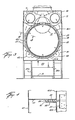
- the overall dryer which is indicated in its entirety by reference character 20, includes a housing 21 supported above a surface 22, and an open-ended drum 23 mounted within the housing for rotation with respect thereto about a generally horizontal axis. More particularly, the housing 21 includes an outer portion having front and rear walls 25 and 26, side walls 27 and 28, and top and bottom walls 29 and 30. The bottom wall of the outer housing is supported above the surface 22 by a base having a bottom wall 31, side walls 27A and 29A, an open front end 25A and a rearwall 26A, whose lower ends support wall 31 above the surface 22.
- top and bottom walls 29 and 30 of the upper housing portion are inclined at a small angle with respect to the horizontal, and as will be described, drum 23 is mounted within the upper housing portion for rotation about an axis which extends at the same angle.
- the front wall 25 of the outer housing has an opening 32 opposite the open upper end of the drum, and the rear wall 26 of the outer housing has an opening 34 opposite the open lower end of the drum.
- the opening 32 and thus the upper end of the drum are adapted to be covered and uncovered by means of a door 33 mounted within a pocket formed within the front wall and vertically movable therein in response to a fluid actuator 33A.
- the opening 34 and thus the lower end of the drum are adapted to be opened and closed by means of a door 35 pivotally mounted on the housing, as will be described.
- wet goods on a conveyor 50 may be loaded into the drum through opening 32 when door 33 is open, and may be unloaded therefrom through opening 34 when door 35 is open.
- the upper edge of door 35 is pivotally mounted on the housing for swinging between a closed position, as shown in solid lines in Fig. 1, and an open position as shown by broken lines in Fig. 1.
- An operator for so moving the door includes an arm 36 connecting the door to a reciprocable actuator 38 supported on a bracket 37 on the housing. As shown in Fig. 1, the actuator may be extending to swing the door against the outer side of wall 26 to close opening 34, or contracted to swing the door to a position in which dried goods may slide out of the lower end of the drum.
- the drum 23 extends from one end to the other of the housing to dispose its opposite ends adjacent the front and rear walls, and is supported within and rotated with respect to the housing by means of rollers 42 near each end and on opposite sides of the lower half of the drum. These rollers are mounted on shafts 43 which extend lengthwise of the drum and have their opposite ends journalled in the front and rear walls 25 and 26 of the housing. At least one of the shafts is driven by means of an electric motor 44 mounted beneath the wall 30 of the housing and outside of the wall 28A and connected by a belt 45 to a sheave one end of the shaft, as shown in Fig. 1.
- Each end of the drum has an outwardly extending flange 46 thereon, with the flange on its upper end facing the inner side of adjacent front wall 25 of the housing, and with the flange on its lower end fitting within opening 34 in rear wall 26 of the outer housing.
- the flange on the upper end of the drum may carry a seal for sliding engagement with the wall 25, and the flange on the lower end thereof is adjacent to the door 35 when closed.
- the drum is held against axial movement with respect to the housing by means of a roller assembly comprising a pair of rollers 47 mounted on a bracket 48 in the housing in position to engage opposite sides of the flange 46 on the upper end of the drum.
- the housing 21 includes an inner portion having a shell 40 which extends for the length of the drum intermediate its flange 46, and which includes arcuate sections 40A and 40B disposed in spaced-apart relation about the upper and lower ends, respectively, of the drum.
- a duct 52 connects a hole in bottom wall 30 of the outer housing with an opening in the bottom of arcuate portion 40B to form an inlet to the space about the drum, and an opening 40C in the bottom of arcuate portion 40A forms an outlet from the space about the drum.
- the inner housing portion also includes a transverse wall 51 which extends between shell 40 intermediate portions 40A and 40B and the side walls 27 and 28 and the top and bottom walls 29 and 30 of the housing to separate the space within the housing, and the outer portion of a ring 60 of Teflon or other low friction material having an inner diameter which closely surrounds the drum is mounted closely within an annular recess 61 formed about the inner portion of the shell adjacent the wall 51 intermediate the inlet to and outlet from the space.
- the cylindrical wall of the drum is perforated on both sides of the ring 60, so that, when the ends of the drum are closed during rotation, the close confinement of the ring within the recess will substantially seal between the drum and wall will substantially confine hot air entering inlet 52 to flow through the perforations into the drum to the right of ring 60 and axially through the drum and out the perforations in the drum to the left of the ring into outlet 40C.
- a wall 62 extends radially outwardly'from the cylindrical wall of the shell and a flange 63 on the outer of wall 62 connects with the wall 51 to form the recess.
- the ring 60 fits closely about an unperforated annular portion of the drum, so that, for purposes previously described, such portion forms a heat sink.
- recess 61 is of such size that, as previously described, the ring is free to move radially with the drum during eccentric drum rotation without wear on the ring.
- the wall 62 and flange 63 are interrupted adjacent the upper side of the drum and the arcuate shell portion 40A is slotted to receive a bracket 64 which connects the ends 60A and 60B of the ring 60 to one another and is mounted on the wall 51 of the inner housing by rivets 65.
- the ends of the ring overlap and are yieldably urged toward one another to hold the ring tightly about the drum 23.
- rods 66 connected to each end of the ring extend through flanges 67 on the ends of the bracket, and coil springs 68 are compressed between the outer sides of the flanges 67 and spring retainers 69 mounted on the outer ends of the rods by lock nuts, whereby the force of the springs may be adjusted in order to control the extent to which the ring is tight about the drum.
- the drum 23 must be free to rotate within the ring 60, the ring is nevertheless sufficiently tight about the drum that substantially all the heated air pass must move axially through the drain.
- the duct 52 is formed by side walls 53 and end walls 54 extending downwardly from an opening in the bottom of the arcuate portion 40B to the opening in bottom wall 30.
- the left-hand rollers 42 extend through slots in shell portion 40A and into the upper space portion to support the upper end of the drum, and the right-hand rollers extend.through slots in shell portion 40A and into the lower space portion to support the lower end of the drum.
- a gas burner 55 is mounted on bottom wall 31 of the base of the housing adjacent its open left end, and gas is supplied to the burner by means of piping 56 extending thereto from a suitable source, whereby fresh air is heated before passing through the duct in the base and into the inlet 52, and thus into the lower space portion between the drum and the shell of the inner housing on the right side of ring 60.
- a first baffle 58 extends upwardly from the bottom wall 31 of the chamber within the housing to a height above that of the burner outlets, and another baffle 59 extends downwardly from the intermediate wall 30 within the chamber to a level substantially in horizontal alignment with the upper end of the baffle 58. Consequently, the baffles cooperate to not only cause mixing of the heated air with fresh air, but also prevent any direct path between the flames of the burner and the inlet. Obviously, fresh air entering the duct may be heated by other appropriate heat sources.
- Openings are formed in the top wall 29 of the outer housing above the shell portion 40A about the upper end of the drum to the left of wall 51 so as to connect with plenums 70 mounted on the top wall and connecting at their right-hand ends with suction blowers 71 also mounted on the top wall 29 towards the rear end of the housing.
- heated air is caused to circulate from within the drum and through its perforations into the upper space portion to the left of ring 60. More particularly, and as will best be understood from Figs. 1 and 3, heated air in the upper space portion must pass through outlet 40C therefrom and then over the top of the arcuate portion 40A to the left of wall 51 before entering the openings leading to the air blower plenum. In this way, goods are prevented from collecting in the upper portion of the left-hand end of the drum, and thus restricting air flow, before circulating into the outlet from the space portion.
- the inclination of the drum with respect to the horizontal may be in the order of 7.5 degrees, and, in any case, is so well selected as to cause wet goods to slide downwardly to its lower end, but to permit dried goods to settle uniformly over the bottom of the drum under the influence of the heated air passing axially therethrough.
- the seal ring 60' is similar to seal ring 60 in that its inner diameter fits closely about the periphery of the drum 23 and its outer portion has opposite sides received closely within the sides of the recess 61 and an outer end spaced from the outer end of the recess, all as shown in Fig. 4.
- the ring differs in cross-section in that it is "T" shaped having a wide flange providing its inner diameter which fits closely about the drum, and a narrow web fitting within the annular recess 61.
- the wide flange on the inner diameter of the seal ring 60' provides a greater cross-sectional area so as to better distribute wear during rotation of the drum within the ring.
- the overlapping ends 60'A and 60'B of the ring 60' are connected to the bracket 64 on the wall 51 in a manner which is particularly well suited for a ring made of Teflon or other plastic material having not only low friction characteristics and high resistance to temperatures which would be encountered in a tumble dryer or the like, but also low tensile strength. More particularly, the ends of the ring 60' are so connected to the bracket 64 as to retain the ring in close fitting relation about the drum 23 despite the tendency of the Teflon to soften at these elevated temperatures, and thus, if connected to the bracket in the manner previously described, possibly permit the clevis pin to pull through one or both ends.
- the web of the ring 60' intermediate its flange and the shell wall 40A at the inner end of the recess in which the outer portion of the ring is received as first and second sets of holes 70 and 71, respectively, formed therein at spaced locations along the length of the ring, with alternate rings of each set extending in opposite diagonal directions.
- first and second sets of holes 70 and 71 respectively, formed therein at spaced locations along the length of the ring, with alternate rings of each set extending in opposite diagonal directions.
- the leftmost hole of the adjacent holes of set 70 shown in Fig. 12 extends downwardly and to the right, while the rightmost hole thereof extends upwardly and to the right.
- the leftmost hole of the adjacent holes of set 71 extends upwardly and to the right, while the rightmost hole thereof extends downwardly and to the right.
- a first wire 73 is laced successively through alternate holes of the first set of holes 70
- a second wire 74 is laced successively through alternate holes of the second set of holes 71, whereby both wires extend alternately over longitudinally spaced portions of opposite sides of the ring-i.e., front and back, as seen in Fig. 11 and top and bottom as seen in Fig. 12.
- the ends of the wires which extend from the endmost hole of each set of holes at each end of the ring are connected to one another, the pin of a clevis 75 extends through a loop on their connected ends.
- the clevis in turn is connected to a rod 66 extending through a hole in a flange 67 of the bracket, and a coil spring 68 is disposed between the outer side of the flange and a spring retainer 69 on the outer end of the rod so as to yieldably pull the ends of the ring 60' in opposite directions, as previously described in connection with the ring 60.
- each hole of each set is substantially adjacent a hole of the other set which extends in the opposite diagonal direction, so that wires 73 and 74 cross one another at the adjacent holes so as to extend substantially coextensively of one another on opposite sides of the web of the ring. More particularly, as shown, the holes cross one another generally intermediate the sides of the web of the ring, and intersect one another so that the wires 73 and 74 will also be adjacent to one another as they cross within adjacent holes of the two sets.
- the seal ring 60" may be identical to the seal ring 60' of the embodiment of Figs. 11 and 12 insofar as its cross-sectional shape and material are concerned, the difference between them residing in the manner in which wires are laced through holes in the web of the ring to hold the inner diameter of the ring closely about the drum 23.
- the outer portion of the ring 60" has opposite sides which fit closely within the opposite sides of the annular recess 61, and an outer end which is spaced from the outer end of the recess so as to permit radial movement between them during rotation of the drum.
- the two sets of holes 76 and 77 are similar to those of the sets of holes 70 and 71 of ring 60' in that alternate ones of each set are equally spaced apart and extend in opposite diagonal directions, and further in that each hole of each set is substantially adjacent a hole of the other set which extends in an opposite diagonal direction.
- the holes of one set do not cross those of the other, but instead are staggered with respect to one another in a longitudinal sense. More particularly, and as best shown in Fig. 14, the adjacent holes of each set intersect one another at alternate sides of the web of the ring.
- door 33 is opened and door 35 closed to permit wet clothes or other cloth goods to be dried to be loaded into the dryer by means of the conveyor 50.
- the drum may be rotated to tumble the goods therein and, for this purpose, there are longitudinal ribs on the inner diameter of the cylindrical wall of the drum.
- the air blower is started so as to cause fresh air to be drawn over the gas burner and thereby heated as it passes through the inlet and lower space portion into the drum, and then axially through the drum and out the perforations to the left of the ring 60 (or ring 60' or 60") into the upper space portion, and from there out of the dryer through the air blower.
- the goods will gravitate toward the lower right-hand end of the drum, and thus to a position for the heated air to pass through them as it first enters the upper housing portion.
- the hot air leaves the upper end of the drum, it must pass beneath the upper edges of outlet 40A before passing into the air blower.
- the gas burner extinguished, and door 35 opened to permit the dried goods to be unloaded through the lower end of the drum.
- the inclination of the drum will facilitate unloading through the opening in its right-hand end.
Landscapes
- Engineering & Computer Science (AREA)
- Textile Engineering (AREA)
- Drying Of Solid Materials (AREA)
- Detail Structures Of Washing Machines And Dryers (AREA)
- Treatment Of Fiber Materials (AREA)
Priority Applications (1)
| Application Number | Priority Date | Filing Date | Title |
|---|---|---|---|
| AT85300110T ATE47609T1 (de) | 1984-02-09 | 1985-01-07 | Vorrichtung zum behandeln von textilien. |
Applications Claiming Priority (4)
| Application Number | Priority Date | Filing Date | Title |
|---|---|---|---|
| US57870484A | 1984-02-09 | 1984-02-09 | |
| US578704 | 1984-02-09 | ||
| US06/656,767 US4640024A (en) | 1984-02-09 | 1984-10-01 | Apparatus for treating cloth goods |
| US656767 | 1984-10-01 |
Publications (3)
| Publication Number | Publication Date |
|---|---|
| EP0152167A2 EP0152167A2 (en) | 1985-08-21 |
| EP0152167A3 EP0152167A3 (en) | 1986-08-06 |
| EP0152167B1 true EP0152167B1 (en) | 1989-10-25 |
Family
ID=27077551
Family Applications (1)
| Application Number | Title | Priority Date | Filing Date |
|---|---|---|---|
| EP85300110A Expired EP0152167B1 (en) | 1984-02-09 | 1985-01-07 | Apparatus for treating cloth goods |
Country Status (10)
| Country | Link |
|---|---|
| US (1) | US4640024A (da) |
| EP (1) | EP0152167B1 (da) |
| AU (1) | AU565156B2 (da) |
| BR (1) | BR8500588A (da) |
| CA (1) | CA1247855A (da) |
| DE (1) | DE3573937D1 (da) |
| DK (1) | DK161462C (da) |
| ES (1) | ES539850A0 (da) |
| MX (1) | MX160526A (da) |
| NZ (1) | NZ211085A (da) |
Families Citing this family (5)
| Publication number | Priority date | Publication date | Assignee | Title |
|---|---|---|---|---|
| US5121615A (en) * | 1991-06-05 | 1992-06-16 | Taiwan Electric Heating Equipment Co., Ltd. | Drying device incorporated with a washing machine |
| NL1000389C2 (nl) * | 1995-05-18 | 1996-11-19 | Amko Int | Inrichting en werkwijze voor het separeren van stukken wasgoed. |
| ES2232472T3 (es) * | 2000-08-01 | 2005-06-01 | Girbau, S.A. | Maquina secadora de ropa de bombo giratorio con descarga automatica. |
| US20050028400A1 (en) * | 2003-08-09 | 2005-02-10 | Matteson Muir Michael | Fabric dryer airflow system and method therefor |
| KR100664290B1 (ko) * | 2006-02-27 | 2007-01-04 | 엘지전자 주식회사 | 의류 건조기의 건조 드럼 |
Family Cites Families (13)
| Publication number | Priority date | Publication date | Assignee | Title |
|---|---|---|---|---|
| DE504967C (de) * | 1925-11-20 | 1930-08-12 | Emil Hahn | Verfahren zum Trocknen mit Feuergasen |
| US2643463A (en) * | 1948-12-11 | 1953-06-30 | Frederick W Grantham | Laundry apparatus |
| US2802283A (en) * | 1955-08-01 | 1957-08-13 | George N Strike | Clothes pre-drier and conditioner |
| US2852236A (en) * | 1956-12-28 | 1958-09-16 | Challenge Mfg Co | Laundry drier door |
| US3067986A (en) * | 1957-11-18 | 1962-12-11 | Joann Grantham | Laundry apparatus |
| US3020648A (en) * | 1958-03-17 | 1962-02-13 | George N Strike | Clothes pre-conditioner and dryer |
| US3316658A (en) * | 1965-04-05 | 1967-05-02 | George N Strike | Two-sided tumbler |
| US3419969A (en) * | 1967-08-23 | 1969-01-07 | Challenge Cook Bros Inc | Tumbler dryer |
| US3526968A (en) * | 1968-01-12 | 1970-09-08 | Fedders Corp | Electronic control circuit for clothes dryers |
| DE1914769A1 (de) * | 1968-04-09 | 1970-06-18 | Arendt Hans F | Trommeltrockner fuer Textilien |
| DE2303980C2 (de) * | 1973-01-27 | 1982-08-12 | Miele & Cie GmbH & Co, 4830 Gütersloh | Trommeltrockner für Wäsche |
| US3902254A (en) * | 1973-10-15 | 1975-09-02 | Mc Graw Edison Co | Laundry system with drying tumbler |
| US4015930A (en) * | 1975-09-04 | 1977-04-05 | Grantham Frederick W | Continuous laundry drying apparatus |
-
1984
- 1984-10-01 US US06/656,767 patent/US4640024A/en not_active Expired - Lifetime
- 1984-12-27 CA CA000471066A patent/CA1247855A/en not_active Expired
-
1985
- 1985-01-04 MX MX203955A patent/MX160526A/es unknown
- 1985-01-07 DE DE8585300110T patent/DE3573937D1/de not_active Expired
- 1985-01-07 EP EP85300110A patent/EP0152167B1/en not_active Expired
- 1985-01-15 AU AU37684/85A patent/AU565156B2/en not_active Ceased
- 1985-01-25 ES ES539850A patent/ES539850A0/es active Granted
- 1985-02-08 DK DK059585A patent/DK161462C/da not_active IP Right Cessation
- 1985-02-08 NZ NZ211085A patent/NZ211085A/en unknown
- 1985-02-08 BR BR8500588A patent/BR8500588A/pt not_active IP Right Cessation
Also Published As
| Publication number | Publication date |
|---|---|
| ES8601354A1 (es) | 1985-11-16 |
| DK161462B (da) | 1991-07-08 |
| MX160526A (es) | 1990-03-16 |
| EP0152167A3 (en) | 1986-08-06 |
| AU565156B2 (en) | 1987-09-03 |
| AU3768485A (en) | 1985-09-05 |
| BR8500588A (pt) | 1985-09-24 |
| US4640024A (en) | 1987-02-03 |
| DK161462C (da) | 1991-12-16 |
| ES539850A0 (es) | 1985-11-16 |
| EP0152167A2 (en) | 1985-08-21 |
| DK59585A (da) | 1985-08-10 |
| DE3573937D1 (en) | 1989-11-30 |
| NZ211085A (en) | 1987-08-31 |
| DK59585D0 (da) | 1985-02-08 |
| CA1247855A (en) | 1989-01-03 |
Similar Documents
| Publication | Publication Date | Title |
|---|---|---|
| US4007546A (en) | Clothes dryer with flexible drum | |
| EP1752575B1 (en) | Washing-drying machine | |
| EP2436830B1 (en) | Tunnel-type rotary-drum tumble dryer | |
| US2372790A (en) | Drier | |
| US4069596A (en) | Air seal arrangement in a clothes dryer | |
| US5421103A (en) | Apparatus and method for drying fabrics | |
| US4510697A (en) | Microwave clothes dryer | |
| US6006445A (en) | Washer/dryer combination | |
| KR20170081938A (ko) | 의류처리장치 | |
| US4640024A (en) | Apparatus for treating cloth goods | |
| US3688906A (en) | Centrifugal dryers | |
| US2802283A (en) | Clothes pre-drier and conditioner | |
| US3409997A (en) | Dryer with open end drum | |
| US3398465A (en) | Clothes dryer with fabric deflecting bulkhead | |
| US3601903A (en) | Tumbler dryer | |
| JP2556902B2 (ja) | 洗濯物等の乾燥方法 | |
| US4593481A (en) | Tumble dryer | |
| GB2308430A (en) | Tumble drier with a rotatably mounted laundry drum | |
| EP0112138A1 (en) | Laundry drying equipment | |
| JPH0444559B2 (da) | ||
| KR880000072B1 (ko) | 드럼식 건조기 | |
| US3419969A (en) | Tumbler dryer | |
| JPH08243290A (ja) | 洗濯乾燥機 | |
| US3321846A (en) | Stationary drum clothes dryer | |
| US5457969A (en) | Top loading vertical axis washing/drying machine |
Legal Events
| Date | Code | Title | Description |
|---|---|---|---|
| PUAI | Public reference made under article 153(3) epc to a published international application that has entered the european phase |
Free format text: ORIGINAL CODE: 0009012 |
|
| AK | Designated contracting states |
Designated state(s): AT BE CH DE FR GB IT LI LU NL SE |
|
| PUAL | Search report despatched |
Free format text: ORIGINAL CODE: 0009013 |
|
| AK | Designated contracting states |
Kind code of ref document: A3 Designated state(s): AT BE CH DE FR GB IT LI LU NL SE |
|
| 17P | Request for examination filed |
Effective date: 19870121 |
|
| 17Q | First examination report despatched |
Effective date: 19880822 |
|
| GRAA | (expected) grant |
Free format text: ORIGINAL CODE: 0009210 |
|
| AK | Designated contracting states |
Kind code of ref document: B1 Designated state(s): AT BE CH DE FR GB IT LI LU NL SE |
|
| REF | Corresponds to: |
Ref document number: 47609 Country of ref document: AT Date of ref document: 19891115 Kind code of ref document: T |
|
| ITF | It: translation for a ep patent filed | ||
| REF | Corresponds to: |
Ref document number: 3573937 Country of ref document: DE Date of ref document: 19891130 |
|
| ET | Fr: translation filed | ||
| PLBE | No opposition filed within time limit |
Free format text: ORIGINAL CODE: 0009261 |
|
| STAA | Information on the status of an ep patent application or granted ep patent |
Free format text: STATUS: NO OPPOSITION FILED WITHIN TIME LIMIT |
|
| 26N | No opposition filed | ||
| ITTA | It: last paid annual fee | ||
| EPTA | Lu: last paid annual fee | ||
| EAL | Se: european patent in force in sweden |
Ref document number: 85300110.5 |
|
| PGFP | Annual fee paid to national office [announced via postgrant information from national office to epo] |
Ref country code: LU Payment date: 19961201 Year of fee payment: 13 |
|
| PGFP | Annual fee paid to national office [announced via postgrant information from national office to epo] |
Ref country code: FR Payment date: 19961216 Year of fee payment: 13 |
|
| PGFP | Annual fee paid to national office [announced via postgrant information from national office to epo] |
Ref country code: SE Payment date: 19961217 Year of fee payment: 13 |
|
| PGFP | Annual fee paid to national office [announced via postgrant information from national office to epo] |
Ref country code: DE Payment date: 19961218 Year of fee payment: 13 |
|
| PGFP | Annual fee paid to national office [announced via postgrant information from national office to epo] |
Ref country code: AT Payment date: 19961219 Year of fee payment: 13 |
|
| PGFP | Annual fee paid to national office [announced via postgrant information from national office to epo] |
Ref country code: GB Payment date: 19961220 Year of fee payment: 13 Ref country code: CH Payment date: 19961220 Year of fee payment: 13 |
|
| PGFP | Annual fee paid to national office [announced via postgrant information from national office to epo] |
Ref country code: NL Payment date: 19961223 Year of fee payment: 13 Ref country code: BE Payment date: 19961223 Year of fee payment: 13 |
|
| PG25 | Lapsed in a contracting state [announced via postgrant information from national office to epo] |
Ref country code: LU Free format text: LAPSE BECAUSE OF NON-PAYMENT OF DUE FEES Effective date: 19980107 Ref country code: GB Free format text: LAPSE BECAUSE OF NON-PAYMENT OF DUE FEES Effective date: 19980107 Ref country code: AT Free format text: LAPSE BECAUSE OF NON-PAYMENT OF DUE FEES Effective date: 19980107 |
|
| PG25 | Lapsed in a contracting state [announced via postgrant information from national office to epo] |
Ref country code: SE Free format text: LAPSE BECAUSE OF NON-PAYMENT OF DUE FEES Effective date: 19980108 |
|
| PG25 | Lapsed in a contracting state [announced via postgrant information from national office to epo] |
Ref country code: LI Free format text: LAPSE BECAUSE OF NON-PAYMENT OF DUE FEES Effective date: 19980131 Ref country code: FR Free format text: THE PATENT HAS BEEN ANNULLED BY A DECISION OF A NATIONAL AUTHORITY Effective date: 19980131 Ref country code: CH Free format text: LAPSE BECAUSE OF NON-PAYMENT OF DUE FEES Effective date: 19980131 Ref country code: BE Free format text: LAPSE BECAUSE OF NON-PAYMENT OF DUE FEES Effective date: 19980131 |
|
| BERE | Be: lapsed |
Owner name: PELLERIN MILNOR CORP. Effective date: 19980131 |
|
| PG25 | Lapsed in a contracting state [announced via postgrant information from national office to epo] |
Ref country code: NL Free format text: LAPSE BECAUSE OF NON-PAYMENT OF DUE FEES Effective date: 19980801 |
|
| GBPC | Gb: european patent ceased through non-payment of renewal fee |
Effective date: 19980107 |
|
| REG | Reference to a national code |
Ref country code: CH Ref legal event code: PL |
|
| NLV4 | Nl: lapsed or anulled due to non-payment of the annual fee |
Effective date: 19980801 |
|
| PG25 | Lapsed in a contracting state [announced via postgrant information from national office to epo] |
Ref country code: DE Free format text: LAPSE BECAUSE OF NON-PAYMENT OF DUE FEES Effective date: 19981001 |
|
| EUG | Se: european patent has lapsed |
Ref document number: 85300110.5 |
|
| REG | Reference to a national code |
Ref country code: FR Ref legal event code: ST |