EP0152638B1 - An mindestens einem Träger aufgehängte Spülkippe - Google Patents
An mindestens einem Träger aufgehängte Spülkippe Download PDFInfo
- Publication number
- EP0152638B1 EP0152638B1 EP84201078A EP84201078A EP0152638B1 EP 0152638 B1 EP0152638 B1 EP 0152638B1 EP 84201078 A EP84201078 A EP 84201078A EP 84201078 A EP84201078 A EP 84201078A EP 0152638 B1 EP0152638 B1 EP 0152638B1
- Authority
- EP
- European Patent Office
- Prior art keywords
- container
- section
- support member
- pivotal
- pivot axle
- Prior art date
- Legal status (The legal status is an assumption and is not a legal conclusion. Google has not performed a legal analysis and makes no representation as to the accuracy of the status listed.)
- Expired
Links
Images

Classifications
-
- E—FIXED CONSTRUCTIONS
- E03—WATER SUPPLY; SEWERAGE
- E03F—SEWERS; CESSPOOLS
- E03F5/00—Sewerage structures
- E03F5/10—Collecting-tanks; Equalising-tanks for regulating the run-off; Laying-up basins
- E03F5/105—Accessories, e.g. flow regulators or cleaning devices
-
- B—PERFORMING OPERATIONS; TRANSPORTING
- B65—CONVEYING; PACKING; STORING; HANDLING THIN OR FILAMENTARY MATERIAL
- B65G—TRANSPORT OR STORAGE DEVICES, e.g. CONVEYORS FOR LOADING OR TIPPING, SHOP CONVEYOR SYSTEMS OR PNEUMATIC TUBE CONVEYORS
- B65G65/00—Loading or unloading
- B65G65/23—Devices for tilting and emptying of containers
-
- E—FIXED CONSTRUCTIONS
- E03—WATER SUPPLY; SEWERAGE
- E03F—SEWERS; CESSPOOLS
- E03F9/00—Arrangements or fixed installations methods or devices for cleaning or clearing sewer pipes, e.g. by flushing
- E03F9/007—Devices providing a flushing surge
Definitions
- the invention relates to a washing tip suspended from at least one support.
- Rinsing tips are used in sewage treatment plants to clean parts of plants, such as basins, rakes and sieves. With a rinsing tip, a large volume of water in the form of a surge can be poured onto a given area for a short time, detaching impurities through mechanical influence and then washing away.
- the suspension takes up a considerable amount of space that can no longer be used for rinsing water, as a result of which the side areas are poorly rinsed, particularly in the case of very narrow basins or sieves.
- very long containers there is a strong deflection in the known suspensions.
- the center of gravity moves in an unpredictable way, so that the tilting no longer occurs at the predetermined point in time.
- the object of the invention is to remedy the disadvantages of the known tipping or to design the tipping such that its shape does not change significantly during filling, regardless of the length of the tipping.
- a rinsing tip is shown with a container 1, which consists of a jacket 2 and these laterally closing end plates 3, 4.
- the container 1 is suspended pivotably about an axis 5.
- the center of gravity S1 of the empty container 1 is to the left of the axis 5 and the state of equilibrium is stable. If the container 1 is filled with rinsing water, the common center of gravity S2 of container 1 and its contents gradually moves to the right side of the axis 5, so that a clockwise swiveling movement of the container 1 and thus the rinsing water are emptied. After emptying, the container 1 swings back into the starting position.
- the container interior 9 is penetrated by supporting members 10 connected to the jacket 2, for example in the form of flat profiles. Further flat profiles 21 can extend to the pouring spout 22 and reinforce the container 1.
- the container 1 is suspended from the ceiling 23 of a plant building on one or more supports 6. With a steel profile 24 and bolt 25 welded to the carrier 6, the latter is rigidly connected to the ceiling. Of course, the steel profile 24 can also be cast into the ceiling 23.
- the carrier 6 consists of a first section 25 which runs vertically in the drawing, a second section 16 which runs at an oblique angle thereto and an even more inclined third section 29, at the end of which a pendulum bearing 18 is attached.
- the curved shape of the carrier 6 means that it can pivot from an upright empty position into a tilted position without incurring loss of content and deflection.
- more than one carrier 6 may be necessary. If, for example, two supports 6 are provided, they are to be attached at a distance 1 of approximately L / 5 from the end plates 3, 4 in order to obtain the least deflection.
- the section 16 serves to determine the end position of the container 1 before and after the pivoting movement.
- a swivel limiter 14 and a reinforcing plate 15 are brought against the jacket 2.
- the inclination of the pivot limiting member 14 and the plate 15 correspond to that of the section 16 when they come into contact with the section 16.
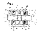
- FIG. 5 shows the self-aligning bearing 18 inserted in a bush 30 at the end of section 29.
- the self-aligning bearing 18 can accommodate any inaccuracies in the container 1 as well as the small, unavoidable deflections.
- a pivot 32 runs through a roller bearing 19 and is fastened to the support members 10.
- the roller bearing 19 is secured on the pivot 32 by a snap groove 33, 34.
- the axes 5 'and 5 "shown in dash-dot lines indicate on an exaggerated scale the deviations from the geometric axis 5 which can be accommodated by the bearing 18.
Landscapes
- Engineering & Computer Science (AREA)
- Health & Medical Sciences (AREA)
- Life Sciences & Earth Sciences (AREA)
- Hydrology & Water Resources (AREA)
- Public Health (AREA)
- Water Supply & Treatment (AREA)
- Mechanical Engineering (AREA)
- Sanitary Device For Flush Toilet (AREA)
- Physical Water Treatments (AREA)
- Drying Of Solid Materials (AREA)
- Tents Or Canopies (AREA)
Description
- Die Erfindung betrifft eine an mindestens einem Träger aufgehängte Spülkippe gemäss Oberbegriff des Patentanspruches 1.
- Spülkippen werden in Kläranlagen zum Reinigen von Anlageteilen, beispielsweise Becken, Rechen und Sieben verwendet. Mit einer Spülkippe kann kurzzeitig ein grosses Volumen Wasser in Form eines Schwalls auf eine vorgegebene Fläche geschüttet werden, unnverunreinioungen durch mechanischen Einfluss abzulösen und anschliessend fortzuschwemmen.
- Die bekannten Spülkippen sind an deren Endplatten an Trägern aufgehängt (CB-PS 590 980 und DE-A-3,208,920).
- Bei diesen Spülkippen beansprucht die Aufhängung erheblich viel Raum, der nicht mehr für Spülwasser nutzbar ist, wodurch insbesondere bei sehr schmalen Becken oder Sieben die seitlichen Bereiche schlechter durchspült werden. Bei sehr langen Behältern tritt bei den bekannten Aufhängungen eine starke Durchbiegung ein. Dies bedeutet einerseits, dass der Behälter verstärkt werden muss und anderseits kann ein durchhängender Behälter nicht bis zum theoretisch möglichen Volumen gefüllt werden. Des weiteren wandert der Schwerpunkt in unberechenbarer Weise, so dass das Kippen nicht mehr im vorbestimmten Zeitpunkt erfolgt.
- Die Aufgabe der Erfindung besteht darin, die Nachteile der bekannten Kippen zu beheben, bzw. die Kippe derart zu gestalten, dass sich deren Form während des Füllens nicht wesentlich ändert, und zwar unabhängig von der Länge der Kippe.
- Nach der Erfindung werden diese Aufgaben gemäss den kennzeichnenden Merkmalen des Patentanspruches 1 gelöst. Weitere vorteilhafte Ausführungsformen sind in den abhängigen Ansprüchen beschrieben. Es zeigen:
- Figur 1: Einen Schnitt durch eine Spülkippe entlang Linie 1 - 1 in Figur 2,
- Figur 2: Eine Ansicht in Richtung des Pfeiles A in Figur 1,
- Figur 3: Einen Längsschnitt durch ein Pendellager für die Spülkippe nach Figur 1.
- In den Figuren 1 und 2 ist eine Spülkippe mit einem Behälter 1 gezeigt, der aus einem Mantel 2 und diesen seitlich abschliessenden Endplatten 3,4 besteht. Der Behälter 1 ist um eine Achse 5 schwenkbar aufgehängt. In der Ruhestellung nach Figur 1 ist der Schwerpunkt S1 des leeren Behälters 1 links von der Achse 5 und der Gleichgewichtszustand ist stabil. Wird der Behälter 1 mit Spülwasser gefüllt, so wandert der gemeinsame Schwerpunkt S2 von Behälter 1 und Inhalt allmählich auf die rechte Seite der Achse 5, so dass eine im Uhrzeigersinn verlaufende Schwenkbewegung des Behälters 1 und damit das Ausleeren des Spülwassers erfolgt. Nach dem Entleeren schwenkt der Behälter 1 in die Ausgangslage zurück.
- Der Behälterinnenraum 9 ist von mit dem Mantel 2 verbundenen Traggliedern 10 zum Beispiel in Gestalt von Flachprofilen durchsetzt. Weitere Flachprofile 21 können sich zum Ausgussschnabel 22 erstrecken und den Behälter 1 verstärken.
- An einem oder mehreren Trägern 6 ist der Behälter 1 an der Decke 23 eines Anlagegebäudes aufgehängt. Mit einem am Träger 6 angeschweissten Stahlprofil 24 und Bolzen 25 ist dieser mit der Decke starr verbunden. Selbstverständlich kann das Stahlprofil 24 auch in die Decke 23 eingegoseen sein.
- Der Träger 6 besteht aus einem ersten, in der Zeichnung vertikal verlaufenden Abschnitt 25, einem dazu schiefwinklig verlaufenden zweiten Abschnitt 16 und einem noch stärker geneigten dritten Abschnitt 29, an dessen Ende ein Pendellager 18 angebracht ist.
- Durch die gekrümmte Form des Trägers 6 erreicht man, dass dieser von einer aufrechten leeren Stellung in eine gekippte Stellung schwenken kann, ohne dass durch Einschnitte ein Inhaltsverlust und eine Durchbiegung eintreten können.
- Zwecks Abstützung des durch die versetzt zum Abschnitt 28 liegende Schwenkachse 5 am Träger 6 entstehenden Momentes D wird das Stahlprofil 24 bis über die Schwenkachse 5 hinausgeführt.
- In Abhängigkeit von der Länge L des Behälters 1 können mehr ala ein Träger 6 notwendig sein. Werden beispielsweise zwei Träger 6 vorgesehen, so sind diese in einem Abstand 1 von circa L/5 von den Endplatten 3,4 anzubringen, um die geringste Durchbiegung zu erhalten.
- Der Abschnitt 16 dient zum Festlegen der Endstellung des Behälters 1 vor und nach der Schwenkbewegung. Am Mantel 2 ist ein Schwenkbegrenzungsglied 14 und diesem gegenüber eine Verstärkungsplatte 15 sngebracht. Die Neigung des Schwenkbegrenzungsgliedes 14 und der Platte 15 entsprechen derjenigen des Abschnittes 16, wenn sie in Anlage mit dem Abschnitt 16 gelangen.
- Wenn der gefüllte Behälter 1 im Uhrzeigersinn um die Achse 5 schwenkt, wird die Drehung durch das Schwenkbegrenzungsglied 14 unterbrochen, so dass durch die asymmetriche Gewichtsverteilung im Behälter 1 dieser nach der Entleerung zurückdrehen kann.
- In der Figur 5 ist das in einer Büchse 30 eingesetzte Pendellager 18 am Ende des Abschnittes 29 dargestellt. Das Pendellager 18 vermag allfällig vorhandcne Ungenauigkeiten des Behälters 1 sowie die geringen, nicht vermeidbaren Durchbiegungen aufzunehmen.
- Durch ein Wälzlager 19 verläuft ein Drehzapfen 32, der an den Traggliedern 10 befestigt ist. Das Wälzlager 19 ist durch Sprengrinne 33, 34 auf dem Drehzapfen 32 gesichert. Seitlich des Wälzlagers 19 befinden sich Dichtungsringe 35 und allenfalls noch je ein Filzring 36. Den seitlichen Abschluss des Pendellagers 18 bilden Deckel 57. Die strichpunktiert dargestellten Achsen 5' und 5" deuten in übertriebenem Maßstab die Abweichungen von der geometrischen Achse 5 an, die durch das Lager 18 aufgenommen werden können.
Claims (5)
Priority Applications (1)
| Application Number | Priority Date | Filing Date | Title |
|---|---|---|---|
| AT84201078T ATE23891T1 (de) | 1984-02-03 | 1984-07-23 | An mindestens einem traeger aufgehaengte spuelkippe. |
Applications Claiming Priority (2)
| Application Number | Priority Date | Filing Date | Title |
|---|---|---|---|
| CH509/84 | 1984-02-03 | ||
| CH50984 | 1984-02-03 |
Publications (3)
| Publication Number | Publication Date |
|---|---|
| EP0152638A2 EP0152638A2 (de) | 1985-08-28 |
| EP0152638A3 EP0152638A3 (en) | 1985-09-25 |
| EP0152638B1 true EP0152638B1 (de) | 1986-11-26 |
Family
ID=4188632
Family Applications (1)
| Application Number | Title | Priority Date | Filing Date |
|---|---|---|---|
| EP84201078A Expired EP0152638B1 (de) | 1984-02-03 | 1984-07-23 | An mindestens einem Träger aufgehängte Spülkippe |
Country Status (3)
| Country | Link |
|---|---|
| EP (1) | EP0152638B1 (de) |
| AT (1) | ATE23891T1 (de) |
| DE (1) | DE3461489D1 (de) |
Families Citing this family (5)
| Publication number | Priority date | Publication date | Assignee | Title |
|---|---|---|---|---|
| DE3447863A1 (de) * | 1984-12-31 | 1986-08-14 | Oskar Vollmar GmbH, 7000 Stuttgart | Spuelkippe |
| DE3610737A1 (de) * | 1986-03-29 | 1987-10-01 | Brombach Hansjoerg | Spuelkippe |
| DE3760915D1 (en) * | 1986-04-22 | 1989-12-07 | Werner Nill | Mounting arrangement for a tipping flushing vessel |
| CH673861A5 (de) * | 1987-05-25 | 1990-04-12 | Werner Nill | |
| DE19548240A1 (de) * | 1995-12-22 | 1997-06-26 | Vollmar Oskar Gmbh | Spülkippe |
Family Cites Families (3)
| Publication number | Priority date | Publication date | Assignee | Title |
|---|---|---|---|---|
| US1704437A (en) * | 1927-11-05 | 1929-03-05 | Louis F Katona | Sewer-flushing device |
| CH590980A5 (de) * | 1975-07-24 | 1977-08-31 | Cevdet A Saatci | Spuelkippe |
| DE3208920A1 (de) * | 1982-03-12 | 1983-09-22 | Oskar Vollmar GmbH, 7000 Stuttgart | Spuelkippenanordnung |
-
1984
- 1984-07-23 EP EP84201078A patent/EP0152638B1/de not_active Expired
- 1984-07-23 AT AT84201078T patent/ATE23891T1/de active
- 1984-07-23 DE DE8484201078T patent/DE3461489D1/de not_active Expired
Also Published As
| Publication number | Publication date |
|---|---|
| EP0152638A3 (en) | 1985-09-25 |
| ATE23891T1 (de) | 1986-12-15 |
| DE3461489D1 (en) | 1987-01-15 |
| EP0152638A2 (de) | 1985-08-28 |
Similar Documents
| Publication | Publication Date | Title |
|---|---|---|
| DE9013861U1 (de) | Tauchwand für Regen- und Klärbecken | |
| EP0152638B1 (de) | An mindestens einem Träger aufgehängte Spülkippe | |
| DE2910523C2 (de) | ||
| DE19618843B4 (de) | Vorrichtung zum Giessen von geschmolzenem Material | |
| EP0363645B1 (de) | Entschlackungseinrichtung für Verbrennungsanlagen | |
| EP0470223A1 (de) | Metallurgisches aggregat | |
| DE2257351C3 (de) | Abstreichvorrichtung für am Boden eines Beckens einer Klär- oder Eindickungsanlage befindliche Ablagerungen | |
| EP0819198A1 (de) | Selbstschwimmendes abschöpfgerät | |
| DE2034991B2 (de) | Einrichtung zum Entleeren von Schwimm-Containern | |
| CH641384A5 (de) | Tragturm fuer metallurgische gefaesse. | |
| DE3432619A1 (de) | Selbstfahrendes fahrzeug mit einer kippmuldeneinrichtung | |
| EP0066567A2 (de) | Auf einem Lastfahrzeug anbringbarer Ladekran | |
| DE1949385A1 (de) | Ladevorrichtung | |
| DE3414825C1 (de) | Hubgeschirr | |
| DE2739540B2 (de) | Tragringlagerung für ein metallurgisches Gefäß | |
| DE2724761A1 (de) | Wagen zum tragen grosser behaelter | |
| AT367330B (de) | Waegevorrichtung fuer metallurgische gefaesse | |
| EP0728548B1 (de) | Schmelzbehälter und diesen verwendende Schmelzvorrichtung | |
| DE1530048C (de) | Brammentransportwagen | |
| DE1193418B (de) | Hubkippvorrichtung zum Entleeren von Muellgefaessen in staubfreie Schuettvorrichtungen an Muellsammelwagen | |
| AT361387B (de) | Drehbar und pendelnd aufgehaengter lastbolzen zum ankuppeln eines verladerahmens an einen container | |
| DE4236501C2 (de) | Verwiegevorrichtung für Schüttgüter mit trichterförmigem Wiegebehälter | |
| DE9410208U1 (de) | Vorläuferbrücke zur Schwimmschlammräumung | |
| DE3447863C2 (de) | ||
| DE529025C (de) | Gefaessfoerderanlage |
Legal Events
| Date | Code | Title | Description |
|---|---|---|---|
| PUAI | Public reference made under article 153(3) epc to a published international application that has entered the european phase |
Free format text: ORIGINAL CODE: 0009012 |
|
| PUAL | Search report despatched |
Free format text: ORIGINAL CODE: 0009013 |
|
| AK | Designated contracting states |
Designated state(s): AT BE CH DE FR GB IT LI LU SE |
|
| AK | Designated contracting states |
Designated state(s): AT BE CH DE FR GB IT LI LU SE |
|
| 17P | Request for examination filed |
Effective date: 19850921 |
|
| 17Q | First examination report despatched |
Effective date: 19860430 |
|
| GRAA | (expected) grant |
Free format text: ORIGINAL CODE: 0009210 |
|
| AK | Designated contracting states |
Kind code of ref document: B1 Designated state(s): AT BE CH DE FR GB IT LI LU SE |
|
| REF | Corresponds to: |
Ref document number: 23891 Country of ref document: AT Date of ref document: 19861215 Kind code of ref document: T |
|
| ET | Fr: translation filed | ||
| ITF | It: translation for a ep patent filed | ||
| REF | Corresponds to: |
Ref document number: 3461489 Country of ref document: DE Date of ref document: 19870115 |
|
| REG | Reference to a national code |
Ref country code: CH Ref legal event code: PUE Owner name: WERNER NILL |
|
| PG25 | Lapsed in a contracting state [announced via postgrant information from national office to epo] |
Ref country code: LU Free format text: LAPSE BECAUSE OF NON-PAYMENT OF DUE FEES Effective date: 19870731 |
|
| PLBE | No opposition filed within time limit |
Free format text: ORIGINAL CODE: 0009261 |
|
| STAA | Information on the status of an ep patent application or granted ep patent |
Free format text: STATUS: NO OPPOSITION FILED WITHIN TIME LIMIT |
|
| 26N | No opposition filed | ||
| REG | Reference to a national code |
Ref country code: GB Ref legal event code: 732 |
|
| REG | Reference to a national code |
Ref country code: FR Ref legal event code: TP Ref country code: FR Ref legal event code: MD |
|
| ITPR | It: changes in ownership of a european patent |
Owner name: CESSIONE;WERNER NILL |
|
| BECA | Be: change of holder's address |
Free format text: 920302 *NILL WERNER:EIGENHEIMWEG 45, CH-8404 WINTERTHUR |
|
| BECH | Be: change of holder |
Free format text: 920302 *NILL WERNER |
|
| ITTA | It: last paid annual fee | ||
| EAL | Se: european patent in force in sweden |
Ref document number: 84201078.7 |
|
| PGFP | Annual fee paid to national office [announced via postgrant information from national office to epo] |
Ref country code: SE Payment date: 19950704 Year of fee payment: 12 |
|
| PGFP | Annual fee paid to national office [announced via postgrant information from national office to epo] |
Ref country code: AT Payment date: 19950705 Year of fee payment: 12 |
|
| PGFP | Annual fee paid to national office [announced via postgrant information from national office to epo] |
Ref country code: DE Payment date: 19950714 Year of fee payment: 12 |
|
| PGFP | Annual fee paid to national office [announced via postgrant information from national office to epo] |
Ref country code: FR Payment date: 19950720 Year of fee payment: 12 |
|
| PGFP | Annual fee paid to national office [announced via postgrant information from national office to epo] |
Ref country code: BE Payment date: 19950724 Year of fee payment: 12 |
|
| PGFP | Annual fee paid to national office [announced via postgrant information from national office to epo] |
Ref country code: CH Payment date: 19950727 Year of fee payment: 12 |
|
| PG25 | Lapsed in a contracting state [announced via postgrant information from national office to epo] |
Ref country code: AT Effective date: 19960723 |
|
| PG25 | Lapsed in a contracting state [announced via postgrant information from national office to epo] |
Ref country code: SE Effective date: 19960724 |
|
| PG25 | Lapsed in a contracting state [announced via postgrant information from national office to epo] |
Ref country code: LI Effective date: 19960731 Ref country code: CH Effective date: 19960731 Ref country code: BE Effective date: 19960731 |
|
| BERE | Be: lapsed |
Owner name: NILL WERNER Effective date: 19960731 |
|
| REG | Reference to a national code |
Ref country code: CH Ref legal event code: PL |
|
| PG25 | Lapsed in a contracting state [announced via postgrant information from national office to epo] |
Ref country code: FR Effective date: 19970328 |
|
| PG25 | Lapsed in a contracting state [announced via postgrant information from national office to epo] |
Ref country code: DE Effective date: 19970402 |
|
| EUG | Se: european patent has lapsed |
Ref document number: 84201078.7 |
|
| REG | Reference to a national code |
Ref country code: FR Ref legal event code: ST |
|
| PGFP | Annual fee paid to national office [announced via postgrant information from national office to epo] |
Ref country code: GB Payment date: 19970707 Year of fee payment: 14 |
|
| PG25 | Lapsed in a contracting state [announced via postgrant information from national office to epo] |
Ref country code: GB Free format text: LAPSE BECAUSE OF NON-PAYMENT OF DUE FEES Effective date: 19980723 |
|
| GBPC | Gb: european patent ceased through non-payment of renewal fee |
Effective date: 19980723 |