EP0152821A1 - Splint - Google Patents
Splint Download PDFInfo
- Publication number
- EP0152821A1 EP0152821A1 EP85100906A EP85100906A EP0152821A1 EP 0152821 A1 EP0152821 A1 EP 0152821A1 EP 85100906 A EP85100906 A EP 85100906A EP 85100906 A EP85100906 A EP 85100906A EP 0152821 A1 EP0152821 A1 EP 0152821A1
- Authority
- EP
- European Patent Office
- Prior art keywords
- pin
- bore
- locking
- locking pin
- outline
- Prior art date
- Legal status (The legal status is an assumption and is not a legal conclusion. Google has not performed a legal analysis and makes no representation as to the accuracy of the status listed.)
- Granted
Links
- 239000013013 elastic material Substances 0.000 claims abstract description 3
- 230000001771 impaired effect Effects 0.000 abstract description 2
- 239000002184 metal Substances 0.000 description 2
Images
Classifications
-
- F—MECHANICAL ENGINEERING; LIGHTING; HEATING; WEAPONS; BLASTING
- F16—ENGINEERING ELEMENTS AND UNITS; GENERAL MEASURES FOR PRODUCING AND MAINTAINING EFFECTIVE FUNCTIONING OF MACHINES OR INSTALLATIONS; THERMAL INSULATION IN GENERAL
- F16B—DEVICES FOR FASTENING OR SECURING CONSTRUCTIONAL ELEMENTS OR MACHINE PARTS TOGETHER, e.g. NAILS, BOLTS, CIRCLIPS, CLAMPS, CLIPS OR WEDGES; JOINTS OR JOINTING
- F16B21/00—Means for preventing relative axial movement of a pin, spigot, shaft or the like and a member surrounding it; Stud-and-socket releasable fastenings
- F16B21/06—Releasable fastening devices with snap-action
- F16B21/08—Releasable fastening devices with snap-action in which the stud, pin, or spigot has a resilient part
- F16B21/086—Releasable fastening devices with snap-action in which the stud, pin, or spigot has a resilient part the shank of the stud, pin or spigot having elevations, ribs, fins or prongs intended for deformation or tilting predominantly in a direction perpendicular to the direction of insertion
-
- F—MECHANICAL ENGINEERING; LIGHTING; HEATING; WEAPONS; BLASTING
- F16—ENGINEERING ELEMENTS AND UNITS; GENERAL MEASURES FOR PRODUCING AND MAINTAINING EFFECTIVE FUNCTIONING OF MACHINES OR INSTALLATIONS; THERMAL INSULATION IN GENERAL
- F16B—DEVICES FOR FASTENING OR SECURING CONSTRUCTIONAL ELEMENTS OR MACHINE PARTS TOGETHER, e.g. NAILS, BOLTS, CIRCLIPS, CLAMPS, CLIPS OR WEDGES; JOINTS OR JOINTING
- F16B21/00—Means for preventing relative axial movement of a pin, spigot, shaft or the like and a member surrounding it; Stud-and-socket releasable fastenings
- F16B21/10—Means for preventing relative axial movement of a pin, spigot, shaft or the like and a member surrounding it; Stud-and-socket releasable fastenings by separate parts
- F16B21/12—Means for preventing relative axial movement of a pin, spigot, shaft or the like and a member surrounding it; Stud-and-socket releasable fastenings by separate parts with locking-pins or split-pins thrust into holes
-
- Y—GENERAL TAGGING OF NEW TECHNOLOGICAL DEVELOPMENTS; GENERAL TAGGING OF CROSS-SECTIONAL TECHNOLOGIES SPANNING OVER SEVERAL SECTIONS OF THE IPC; TECHNICAL SUBJECTS COVERED BY FORMER USPC CROSS-REFERENCE ART COLLECTIONS [XRACs] AND DIGESTS
- Y10—TECHNICAL SUBJECTS COVERED BY FORMER USPC
- Y10T—TECHNICAL SUBJECTS COVERED BY FORMER US CLASSIFICATION
- Y10T403/00—Joints and connections
- Y10T403/76—Joints and connections having a cam, wedge, or tapered portion
Definitions
- the invention is characterized in that the locking pin has a rounded cross section form, that the bent-out outline consists of two straight lines having a peak between the two end portions of the pin, that the second outline has a straight part between two shoulders one at each end of the pin, which straight part of said second outline has a length which at least corresponds to the length of the bore, into which the pin is to be inserted, whereby the diameter of the pin measured at said peak and close to the shoulder is somewhat less than the diameter of the bore.
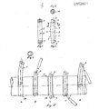
- the pin 1 is made of metal or plastic, but preferably from metal, which has some elastic properties allowing the pin to be bent and resume its original shape. The elastic quality should be such that the pin can be bent by hand.
- the pin 1 is shown from one side in Fig. 1 and the side view in Fig. 2 is turned 90° relative to the view according to Fig. 1.
- the pin 1 has a symmetry plane 2 according to Fig. 1 and the form of the symmetry plane is shown in Fig. 2. From Fig. 2 can be seen the outlines of the pin in the symmetry plane. As can be seen the left outline 3 is bent outwardly with a peak 4 in the middle.
- the object of the locking pin is that it should be insertable into a bore, which is transverse to e.g. a shaft.
- the distance between the two shoulders 6 and 7 should correspond to the approximate length of the bore and the shoulders 6 and 7 should abut the end edges of the bore.
- the pin is rounded and has a circular shape near the shoulders 6 and 7, see Figs 3 and 4.
- the diameter 10 of the shoulders 6 and 7, respectively, corresponds to the diameter of the bore into which the pin is to be inserted.
- the diameter 10 must not be larger, as, if so, the pin cannot be inserted through the bore.
- the diameter of the pin at the peak 4 must not be larger than the diameter of the bore either.
- the locking pin according to the invention has very good locking qualities against axial forces along the direction of the shaft, into the bore of which the pin is inserted. It should be noted that the shoulders 6 and 7 are turned in a direction away from the one towards which the outline of the pin is bulging. This means that if an axial force should happen to bear against the shoulders, the locking pin will turn in the bore at least 90° meaning that the shoulders will not be moved away in the longitudinal direction of the shaft, which should mean that the locking pin was bent and maybe causing the pin to slip out of the bore as the shoulders then are freed from their engagement with the edges of the bore. The locking pin thus has a well fixed position in the bore even if forces along the shaft should try to bend the pin so that the shoulders are freed.
- the locking pin thus shall lock against axial forces having the direction marked with the arrow P in Fig. 5 but a safe locking is also achieved in opposite axial direction, whereby thus the locking pin can turn in the bore 14 or stay in its original position when the turning force does not overcome the friction forces derived from the turning of the pin in the bore.
Landscapes
- Engineering & Computer Science (AREA)
- General Engineering & Computer Science (AREA)
- Mechanical Engineering (AREA)
- Snaps, Bayonet Connections, Set Pins, And Snap Rings (AREA)
- Insertion Pins And Rivets (AREA)
- Impact Printers (AREA)
- Supporting Of Heads In Record-Carrier Devices (AREA)
- Liquid Developers In Electrophotography (AREA)
- Forklifts And Lifting Vehicles (AREA)
Priority Applications (1)
| Application Number | Priority Date | Filing Date | Title |
|---|---|---|---|
| AT85100906T ATE30621T1 (de) | 1984-02-08 | 1985-01-29 | Splint. |
Applications Claiming Priority (2)
| Application Number | Priority Date | Filing Date | Title |
|---|---|---|---|
| SE8400655A SE465282B (sv) | 1984-02-08 | 1984-02-08 | Laassprint |
| SE8400655 | 1984-02-08 |
Publications (2)
| Publication Number | Publication Date |
|---|---|
| EP0152821A1 true EP0152821A1 (de) | 1985-08-28 |
| EP0152821B1 EP0152821B1 (de) | 1987-11-04 |
Family
ID=20354647
Family Applications (1)
| Application Number | Title | Priority Date | Filing Date |
|---|---|---|---|
| EP85100906A Expired EP0152821B1 (de) | 1984-02-08 | 1985-01-29 | Splint |
Country Status (7)
| Country | Link |
|---|---|
| US (1) | US4770587A (de) |
| EP (1) | EP0152821B1 (de) |
| JP (1) | JPS60227007A (de) |
| AT (1) | ATE30621T1 (de) |
| CA (1) | CA1232476A (de) |
| DE (1) | DE3560918D1 (de) |
| SE (1) | SE465282B (de) |
Cited By (1)
| Publication number | Priority date | Publication date | Assignee | Title |
|---|---|---|---|---|
| EP0541363A1 (de) * | 1991-11-05 | 1993-05-12 | Petroleo Brasileiro S.A. - Petrobras | Durch ein ferngesteuertes Fahrzeug betätigte Einrichtung zum Auswechseln von Führungssäulen |
Families Citing this family (2)
| Publication number | Priority date | Publication date | Assignee | Title |
|---|---|---|---|---|
| DE10329007A1 (de) * | 2003-06-27 | 2005-01-13 | Gustav Klauke Gmbh | Verriegelungsbolzen zur Befestigung eines Werkzeuges an einem hydraulischen Verpressgerät |
| DE102018200925A1 (de) * | 2018-01-22 | 2019-07-25 | Brose Fahrzeugteile Gmbh & Co. Kommanditgesellschaft, Bamberg | Mitnehmer mit schwenkbarem Klemmteil und Montageverfahren |
Citations (5)
| Publication number | Priority date | Publication date | Assignee | Title |
|---|---|---|---|---|
| DE327943C (de) * | 1918-09-05 | 1920-10-19 | Arthur Graham France | Vorstecker |
| US2464381A (en) * | 1947-06-12 | 1949-03-15 | Williams J H & Co | Coupling |
| US2537841A (en) * | 1945-08-30 | 1951-01-09 | Jr John A Maclean | Cotter key |
| DE897178C (de) * | 1951-12-16 | 1953-11-19 | Heinz Wolfgang Wallenfels | Sicherung loesbarer Bolzen |
| DE1644963A1 (de) * | 1967-03-10 | 1971-04-29 | Shell Int Research | Esterschmieroel |
Family Cites Families (11)
| Publication number | Priority date | Publication date | Assignee | Title |
|---|---|---|---|---|
| US2047295A (en) * | 1935-03-22 | 1936-07-14 | Sipos Frank | Cotter pin |
| US2129420A (en) * | 1937-02-18 | 1938-09-06 | Guy And Murton Inc | Cotter pin |
| US2370171A (en) * | 1943-08-20 | 1945-02-27 | Jepson Percy | Locking pin |
| US2651390A (en) * | 1950-04-14 | 1953-09-08 | American Steel Foundries | Brake head arrangement |
| US3022586A (en) * | 1959-05-18 | 1962-02-27 | Gen Metals Corp | Retainer for bucket teeth |
| US3025619A (en) * | 1959-05-18 | 1962-03-20 | Gen Metals Corp | Spring retainer for bucket teeth |
| US3175314A (en) * | 1959-08-03 | 1965-03-30 | Caterpillar Tractor Co | Retaining pin for telescoped parts comprising separate longitudinally bowed sequentially insertable resilient members |
| US3494245A (en) * | 1968-10-14 | 1970-02-10 | Caterpillar Tractor Co | Resiliently interacting retaining pin |
| US3520224A (en) * | 1969-02-12 | 1970-07-14 | Hensley Equipment Co Inc | Retaining pin |
| US3685178A (en) * | 1970-07-10 | 1972-08-22 | Abex Corp | Dipper teeth |
| DE2713227C2 (de) * | 1977-03-25 | 1983-08-04 | O & K Orenstein & Koppel Ag, 1000 Berlin | Lösbare Befestigung eines rückwärts mit einer Hülse versehenen Baggerzahnes an einem in die Hülse eingreifenden Zahnhalter |
-
1984
- 1984-02-08 SE SE8400655A patent/SE465282B/sv not_active IP Right Cessation
-
1985
- 1985-01-29 AT AT85100906T patent/ATE30621T1/de not_active IP Right Cessation
- 1985-01-29 DE DE8585100906T patent/DE3560918D1/de not_active Expired
- 1985-01-29 EP EP85100906A patent/EP0152821B1/de not_active Expired
- 1985-02-07 CA CA000473828A patent/CA1232476A/en not_active Expired
- 1985-02-07 JP JP60022732A patent/JPS60227007A/ja active Pending
-
1986
- 1986-11-28 US US06/935,138 patent/US4770587A/en not_active Expired - Fee Related
Patent Citations (5)
| Publication number | Priority date | Publication date | Assignee | Title |
|---|---|---|---|---|
| DE327943C (de) * | 1918-09-05 | 1920-10-19 | Arthur Graham France | Vorstecker |
| US2537841A (en) * | 1945-08-30 | 1951-01-09 | Jr John A Maclean | Cotter key |
| US2464381A (en) * | 1947-06-12 | 1949-03-15 | Williams J H & Co | Coupling |
| DE897178C (de) * | 1951-12-16 | 1953-11-19 | Heinz Wolfgang Wallenfels | Sicherung loesbarer Bolzen |
| DE1644963A1 (de) * | 1967-03-10 | 1971-04-29 | Shell Int Research | Esterschmieroel |
Cited By (1)
| Publication number | Priority date | Publication date | Assignee | Title |
|---|---|---|---|---|
| EP0541363A1 (de) * | 1991-11-05 | 1993-05-12 | Petroleo Brasileiro S.A. - Petrobras | Durch ein ferngesteuertes Fahrzeug betätigte Einrichtung zum Auswechseln von Führungssäulen |
Also Published As
| Publication number | Publication date |
|---|---|
| EP0152821B1 (de) | 1987-11-04 |
| JPS60227007A (ja) | 1985-11-12 |
| SE465282B (sv) | 1991-08-19 |
| US4770587A (en) | 1988-09-13 |
| SE8400655D0 (sv) | 1984-02-08 |
| DE3560918D1 (en) | 1987-12-10 |
| SE8400655L (sv) | 1985-08-09 |
| CA1232476A (en) | 1988-02-09 |
| ATE30621T1 (de) | 1987-11-15 |
Similar Documents
| Publication | Publication Date | Title |
|---|---|---|
| US4726783A (en) | Locking mechanism for connectors | |
| US4032178A (en) | Electric conduit connector | |
| KR900006086A (ko) | 푸쉬-인 패스너 | |
| EP0801968A3 (de) | Bausteine mit verformbaren Kupplungen | |
| US5815891A (en) | Cable tie with bent barb | |
| EP0412436A2 (de) | Selbstverriegelnde Verbindungsstruktur zum Verbinden von Zusatzeinrichtungen mit profilierten Elementen | |
| US20010010791A1 (en) | Nut assembly with pivotable nut | |
| EP0152821B1 (de) | Splint | |
| US3695652A (en) | Actuator rod connector | |
| US20040001738A1 (en) | Tube fastener apparatus | |
| US5624724A (en) | Self retainable shim | |
| US20100284761A1 (en) | Press Type Fastener | |
| US3220679A (en) | Assemblies for mounting mouldings on utility poles | |
| GB2185081A (en) | Screw anchor | |
| US4770546A (en) | Tension bush | |
| EP1234923B1 (de) | Schnellverbinder für Armierungseisen an Eingussdübel | |
| US3458993A (en) | Ball chain connector element | |
| US4460900A (en) | Device for mounting an antenna element on an antenna supporting spar | |
| US4997306A (en) | Joint for reinforcing bars | |
| US4097966A (en) | Binding clip for bundling and/or attaching cables and similar objects | |
| US3340704A (en) | Flexible coupling | |
| US4093387A (en) | Fastener for detachably interconnecting punched documents | |
| US4699553A (en) | Cotter ring locking device | |
| US5207529A (en) | Fastening device | |
| US4844646A (en) | Clamp members |
Legal Events
| Date | Code | Title | Description |
|---|---|---|---|
| PUAI | Public reference made under article 153(3) epc to a published international application that has entered the european phase |
Free format text: ORIGINAL CODE: 0009012 |
|
| AK | Designated contracting states |
Designated state(s): AT CH DE FR GB IT LI |
|
| 17P | Request for examination filed |
Effective date: 19850520 |
|
| R17P | Request for examination filed (corrected) |
Effective date: 19850520 |
|
| 17Q | First examination report despatched |
Effective date: 19861117 |
|
| GRAA | (expected) grant |
Free format text: ORIGINAL CODE: 0009210 |
|
| AK | Designated contracting states |
Kind code of ref document: B1 Designated state(s): AT CH DE FR GB IT LI |
|
| REF | Corresponds to: |
Ref document number: 30621 Country of ref document: AT Date of ref document: 19871115 Kind code of ref document: T |
|
| ITF | It: translation for a ep patent filed | ||
| REF | Corresponds to: |
Ref document number: 3560918 Country of ref document: DE Date of ref document: 19871210 |
|
| ET | Fr: translation filed | ||
| PLBE | No opposition filed within time limit |
Free format text: ORIGINAL CODE: 0009261 |
|
| STAA | Information on the status of an ep patent application or granted ep patent |
Free format text: STATUS: NO OPPOSITION FILED WITHIN TIME LIMIT |
|
| 26N | No opposition filed | ||
| PGFP | Annual fee paid to national office [announced via postgrant information from national office to epo] |
Ref country code: GB Payment date: 19910121 Year of fee payment: 7 |
|
| PGFP | Annual fee paid to national office [announced via postgrant information from national office to epo] |
Ref country code: CH Payment date: 19910125 Year of fee payment: 7 Ref country code: FR Payment date: 19910125 Year of fee payment: 7 |
|
| ITTA | It: last paid annual fee | ||
| PGFP | Annual fee paid to national office [announced via postgrant information from national office to epo] |
Ref country code: AT Payment date: 19910131 Year of fee payment: 7 |
|
| PGFP | Annual fee paid to national office [announced via postgrant information from national office to epo] |
Ref country code: DE Payment date: 19910226 Year of fee payment: 7 |
|
| PG25 | Lapsed in a contracting state [announced via postgrant information from national office to epo] |
Ref country code: GB Effective date: 19920129 Ref country code: AT Effective date: 19920129 |
|
| PG25 | Lapsed in a contracting state [announced via postgrant information from national office to epo] |
Ref country code: LI Effective date: 19920131 Ref country code: CH Effective date: 19920131 |
|
| GBPC | Gb: european patent ceased through non-payment of renewal fee | ||
| PG25 | Lapsed in a contracting state [announced via postgrant information from national office to epo] |
Ref country code: FR Effective date: 19920930 |
|
| REG | Reference to a national code |
Ref country code: CH Ref legal event code: PL |
|
| PG25 | Lapsed in a contracting state [announced via postgrant information from national office to epo] |
Ref country code: DE Effective date: 19921001 |
|
| REG | Reference to a national code |
Ref country code: FR Ref legal event code: ST |