EP0152899A2 - Sac en matière plastique à poignée - Google Patents
Sac en matière plastique à poignée Download PDFInfo
- Publication number
- EP0152899A2 EP0152899A2 EP85101502A EP85101502A EP0152899A2 EP 0152899 A2 EP0152899 A2 EP 0152899A2 EP 85101502 A EP85101502 A EP 85101502A EP 85101502 A EP85101502 A EP 85101502A EP 0152899 A2 EP0152899 A2 EP 0152899A2
- Authority
- EP
- European Patent Office
- Prior art keywords
- legs
- shaped
- handle
- carrying
- carrying bag
- Prior art date
- Legal status (The legal status is an assumption and is not a legal conclusion. Google has not performed a legal analysis and makes no representation as to the accuracy of the status listed.)
- Granted
Links
Images


Classifications
-
- B—PERFORMING OPERATIONS; TRANSPORTING
- B65—CONVEYING; PACKING; STORING; HANDLING THIN OR FILAMENTARY MATERIAL
- B65D—CONTAINERS FOR STORAGE OR TRANSPORT OF ARTICLES OR MATERIALS, e.g. BAGS, BARRELS, BOTTLES, BOXES, CANS, CARTONS, CRATES, DRUMS, JARS, TANKS, HOPPERS, FORWARDING CONTAINERS; ACCESSORIES, CLOSURES, OR FITTINGS THEREFOR; PACKAGING ELEMENTS; PACKAGES
- B65D33/00—Details of, or accessories for, sacks or bags
- B65D33/16—End- or aperture-closing arrangements or devices
- B65D33/1683—A pair of interconnecting rigid strips made of plastic material, e.g. one or both being provided with a handle or suspension means
Definitions
- the invention relates to a carrier bag according to the preamble of claim 1.
- a carrier bag of this type in which the wall opposite the wall provided with the bar carrying the handle is extended by an envelope part which is provided in the area of its folded edge with a push-through slot for the handle.
- the carrying handle can pull up the flap formed by the envelope part when the carrying bag is filled, so that the bag partially opens and dust or Rain can occur.
- a raised envelope part of the carrier bag gives an unsightly appearance.
- the object of the invention is therefore to provide a well-closing and shapely carrier bag according to the preamble of claim 1.
- the opening edge of the opposite wall of the bag is also stiffened by a strip so that it cannot hang down unsightly after the bag has been filled.
- the stiffening strip is directly connected to the carrying handle through the slot, so that a good closure is guaranteed.
- the carrying case according to the invention provides increased security against theft, because it can only be opened by noticeably pushing the side parts of the carrying handle through the slot.
- Carrier bags are already known with strips welded to both opening edges with bow-like carrying handles, which are provided with snap-type locking connections. To close these bags, however, the connecting elements must be aligned relative to each other, which is cumbersome and therefore generally not done so that the bags are not closed and their contents are endangered by dust and rainwater; the snap fasteners also damage sensitive fabrics or surfaces (stitching).
- the tote bag according to the invention can be easily closed by gripping the bow-shaped handle after pushing it through the slot, whereupon the tote bag closes automatically and remains closed under the weight of the bag contents. This also speeds up the closing process considerably compared to conventional carrier bags.
- the flat snap-in connections seal the bags better against the ingress of rain and dust.
- the legs of the carrying handle are expediently provided just above the bar with outwardly pointing hook-shaped projections which, in the closed state, engage behind the short legs of the bracket delimiting the push-through slot.
- These hook-shaped projections expediently have beveled flanks on their top, on which the web parts of the push-through slot slip until they snap behind the hook-shaped projections, which are formed by approximately horizontal indentations which close off the oblique flanks.
- the legs of the carrying handle pushed through the through-slot can also have, on their front side, gripped by the web of the U-shaped strip, projections or ridges which form locking shoulders which engage in a latching manner over the web.
- the carrying case according to the invention can be handled well and ensures a simple and secure closure simply by the web that delimits the push-through slot snapping over the shoulders or projections.
- the bow-shaped handle seized to close the carrying case after pushing through the push-through slot the carrying bag closes automatically under the weight of the bag contents by the tensioned front wall of the carrying bag pulling the push-through slot into its closed position, in which the web of the push-through slot is locked and the Place the stiffening welding strips centering on one another and the bag remains closed.
- the projections do not have to extend across the width of the legs, they can also be designed in the form of points or nubs.
- the projections are expediently provided with beveled run-up surfaces in the direction of the outer handle end, which promotes the snap-in of the web delimiting the push-through slot into the closed position.
- the legs provided with hook-shaped latching projections can also be connected to one another by a web carrying a hook or an eyelet instead of a handle part connecting them. Bags designed in this way can be filled with goods and attached to sales stands.
- the carrying handle and the bracket delimiting the push-through slot can, with the associated strips, consist of soft, flexible plastic injection-molded parts, so that there is good flexibility when pushing the carrying handle through the push-through slot.
- the carrying handle and the stiffening strips are expediently stiffened by profiling, which means that additional material can be saved.
- the object is achieved according to the invention by the characterizing part of patent claim 10.
- This embodiment of the carrier bag according to the invention can also be handled well and ensures a simple and secure closure simply by the fact that the tab-shaped fort sentences are inserted through the eyelet formed by the handle in such a way that they engage behind legs of the handle. If the bow-shaped carrying handle is obtained after inserting or pushing through the tab-shaped extensions, the strips stiffening the opening edges center relative to one another in that the tab-shaped shoulders are supported on widenings of the carrying handle legs or the strip connected to them.
- the lobe-shaped projections expediently protrude above the legs.
- the tab-shaped extensions can also be connected to the web via an offset, so that after being pushed through the eyelet formed with the carrying handle, they do not need to be pressed behind the carrying handle leg.
- the legs can be provided on their outer sides with the projections overlapping hook-shaped, so that the projections snap into their closed position after being pushed through the carrying handle eyelet under the load of the bag filling or by hand pressure.
- the end regions of the extensions can also be curved behind the legs and the legs can be provided with hook-shaped parts overlapping the end regions on their narrow outer sides.
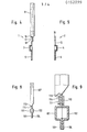
- the handle part 1 and the slot part 2 consist of stiffening strips 3, 4 with a U-shaped profile.
- Strips 5, 6 are formed at right angles to the lower legs of these profiles.
- One profile is provided at intervals with approximately rectangular projections 7, while the other profile to these has complementary recesses 8 so that the profiled strips 3, 4 can latch together.
- the bar 3 is provided with a bow-shaped handle part 9, the legs 10, 11 are provided with the upper leg of the profiled handle part 3.
- the upper leg of the profiled strip 4 is provided with a flat, U-shaped, bow-shaped part which delimits the push-through slot 12.
- This bow-shaped part consists of short legs 13, 14 which are integrally connected to the bar 4 and which are connected to one another by the web part 15.
- the rectangular cross-section slot 12 corresponds in its opening cross section to the vertical projection of the handle part 9 onto the upper leg of the bar 3.
- the grip part 9 consists of an upper, approximately oval part and a lower leg part attached via a kink. These lower leg parts are provided on their outside gripped by the web 15 with a step-shaped hook-shaped parts 16, 17. These hook-shaped parts 16, as can best be seen from FIG. 4, are formed by steps 17 provided in the leg regions of the handle part 9. This step 17 can be followed by a groove-like depression 18, the width of which corresponds approximately to the width of the web 15 delimiting the slot 12.
- the position of the web 15 in the closed position has been indicated by dashed lines in FIG. 2.
- the web 15 is overlapped by the step-like projection 17 and locked by this.
- the inner sides of the short legs 13, 14 lie approximately on the outer sides of the handle legs 10, 11, so that the strips 3, 4 are locked together in the closed position via the handle and slot parts and are centered relative to one another.
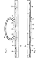
- the strips 101, 102 welded onto the opening edges of the carrier bag in a manner not shown have a U-shaped profile in cross section.
- Strips 103, 104 forming weld-on tabs are integrally formed in one piece on the lower legs of these profiles.
- the profiles are provided at intervals with approximately rectangular projections 105 which can engage in recesses 106 of the other profile which are complementary thereto for latching.
- the bar 101 is provided in one piece with a bow-shaped handle part 107, which has a double-T-shaped profile in its upper regions for its stiffening.
- the legs 108, 109 of the handle part are connected to the upper leg of the bar 101.
- the upper leg of the strip 102 is integrally connected in its central region to a web 110 which widens it and is provided on both sides with freely projecting tab-shaped extensions 111, 112.
- the tab-shaped extensions 111, 112 have to be inserted or pushed through the handle eyelet so that they engage behind the handle legs 108, 109.
- the legs 108, 109 of the bow-shaped handle part 107 can be provided in the manner shown in FIG. 8 with a hook-shaped projection or a groove 114 forming a projection 113, into which the tab-shaped extensions 111, 112 latch intervention.
- the strips 101, 102 have been shown in an aligned position without the lobe-shaped Extensions 111, 112 reach behind the legs.
- the tab-shaped extensions 111, 112 are connected to the central web part 110 by an offset.
Landscapes
- Engineering & Computer Science (AREA)
- Mechanical Engineering (AREA)
- Purses, Travelling Bags, Baskets, Or Suitcases (AREA)
Priority Applications (1)
| Application Number | Priority Date | Filing Date | Title |
|---|---|---|---|
| AT85101502T ATE47107T1 (de) | 1984-02-20 | 1985-02-12 | Tragetasche aus kunststoffolie. |
Applications Claiming Priority (6)
| Application Number | Priority Date | Filing Date | Title |
|---|---|---|---|
| DE8405096U | 1984-02-20 | ||
| DE19848405096 DE8405096U1 (de) | 1984-02-20 | 1984-02-20 | Tragetasche aus Kunststoffolie |
| DE8409385U | 1984-03-27 | ||
| DE19848409385 DE8409385U1 (de) | 1984-03-27 | 1984-03-27 | Tragetasche aus Kunststoffolie |
| DE8419598U | 1984-06-29 | ||
| DE19848419598 DE8419598U1 (de) | 1984-06-29 | 1984-06-29 | Tragetasche aus Kunststoff-Folie |
Publications (3)
| Publication Number | Publication Date |
|---|---|
| EP0152899A2 true EP0152899A2 (fr) | 1985-08-28 |
| EP0152899A3 EP0152899A3 (en) | 1987-12-02 |
| EP0152899B1 EP0152899B1 (fr) | 1989-10-11 |
Family
ID=27207580
Family Applications (1)
| Application Number | Title | Priority Date | Filing Date |
|---|---|---|---|
| EP85101502A Expired EP0152899B1 (fr) | 1984-02-20 | 1985-02-12 | Sac en matière plastique à poignée |
Country Status (3)
| Country | Link |
|---|---|
| US (1) | US4641360A (fr) |
| EP (1) | EP0152899B1 (fr) |
| DE (1) | DE3573584D1 (fr) |
Cited By (4)
| Publication number | Priority date | Publication date | Assignee | Title |
|---|---|---|---|---|
| FR2617806A1 (fr) * | 1987-07-06 | 1989-01-13 | Cgl Thermoformage Sa | Dispositif de verrouillage et d'accrochage pour boites thermoformees |
| AT390937B (de) * | 1986-11-17 | 1990-07-25 | Jacques Mueller Ag | Tragtaschengriff |
| FR2736521A1 (fr) * | 1995-07-12 | 1997-01-17 | Frank Helmut | Sac a poignee et a dispositif de fermeture de securite |
| ITBS20120026A1 (it) * | 2012-02-21 | 2013-08-22 | Viemme Due S R L | Procedimento per la realizzazione di un involucro ed involucro |
Families Citing this family (9)
| Publication number | Priority date | Publication date | Assignee | Title |
|---|---|---|---|---|
| US4871264A (en) * | 1988-01-05 | 1989-10-03 | Edward S. Robbins, Iii | Bag closure device and methods of fabricating the same |
| CA2032699A1 (fr) * | 1989-12-21 | 1991-06-22 | Hans Dieter Flieger | Dispositif d'assemblage demontable de deux elements jointifs; procede de fabrication dudit dispositif |
| WO1996029277A1 (fr) * | 1995-03-21 | 1996-09-26 | Newlands Paulo Roberto Jannott | Sachet valvulaire etanche a l'air |
| US5813092A (en) * | 1996-02-02 | 1998-09-29 | Monaco, Llc | Hanger handle for a recloseable bag |
| US5944423A (en) * | 1998-04-03 | 1999-08-31 | Monaco, Llc | Bag file for suspension filing system |
| FR2828677B1 (fr) * | 2001-08-17 | 2003-11-14 | Valembal S A | Dispositif de fermeture pour sac |
| DE60321976D1 (de) * | 2003-10-24 | 2008-08-14 | Tama Plastic Ind | Einstellbares kunststofftragband mit seitlich auskragenden falt-griffen |
| US20120082404A1 (en) * | 2010-09-30 | 2012-04-05 | Angela Weir | Ease Open Storage Bag Container |
| US9365325B2 (en) | 2014-06-11 | 2016-06-14 | Michelle Bodner | Child proof containers |
Family Cites Families (12)
| Publication number | Priority date | Publication date | Assignee | Title |
|---|---|---|---|---|
| DE1841040U (de) * | 1960-02-19 | 1961-11-09 | Erik Damgaard Beck | Handtasche. |
| DK110192C (da) * | 1964-12-09 | 1970-05-04 | Svend Georg Hansen | Hank til bæreposer. |
| US3311144A (en) * | 1965-04-06 | 1967-03-28 | Cellu Craft Products Corp | Combined handle and closure member |
| US3353741A (en) * | 1965-08-09 | 1967-11-21 | Thru Products Inc C | Handle for synthetic resinous bags |
| FI46245C (fi) * | 1967-01-04 | 1973-02-12 | Suominen | Hitsattavasta muovikalvosta valmistetun pussin tai kassin suun sulkula ite. |
| FR1527518A (fr) * | 1967-06-16 | 1968-05-31 | Procédé de confection d'un renfort formant des poignées sur un sachet en matière plastique, et sachet obtenu par ce procédé | |
| DE1632564B1 (de) * | 1967-11-03 | 1970-10-01 | Windmoeller & Hoelscher | Tragtaschengriff aus thermoplastischem Kunststoff |
| DE1954944A1 (de) * | 1969-10-31 | 1971-05-06 | Windmoeller & Hoelscher | Traggriff-Tragetasche aus Kunststoffolie |
| US3987958A (en) * | 1975-08-15 | 1976-10-26 | Ctp Industries, Inc. | Hook and handle combination |
| DK347276A (da) * | 1976-08-02 | 1978-02-03 | Int Finanz Gewerbe Und Handels | Berepose |
| GB1575657A (en) * | 1978-05-17 | 1980-09-24 | Peake N | Closure means for a bag |
| US4387846A (en) * | 1981-03-30 | 1983-06-14 | Ducorday Gerard M | Bag handle |
-
1985
- 1985-02-12 EP EP85101502A patent/EP0152899B1/fr not_active Expired
- 1985-02-12 DE DE8585101502T patent/DE3573584D1/de not_active Expired
- 1985-02-20 US US06/703,399 patent/US4641360A/en not_active Expired - Fee Related
Cited By (4)
| Publication number | Priority date | Publication date | Assignee | Title |
|---|---|---|---|---|
| AT390937B (de) * | 1986-11-17 | 1990-07-25 | Jacques Mueller Ag | Tragtaschengriff |
| FR2617806A1 (fr) * | 1987-07-06 | 1989-01-13 | Cgl Thermoformage Sa | Dispositif de verrouillage et d'accrochage pour boites thermoformees |
| FR2736521A1 (fr) * | 1995-07-12 | 1997-01-17 | Frank Helmut | Sac a poignee et a dispositif de fermeture de securite |
| ITBS20120026A1 (it) * | 2012-02-21 | 2013-08-22 | Viemme Due S R L | Procedimento per la realizzazione di un involucro ed involucro |
Also Published As
| Publication number | Publication date |
|---|---|
| EP0152899B1 (fr) | 1989-10-11 |
| US4641360A (en) | 1987-02-03 |
| EP0152899A3 (en) | 1987-12-02 |
| DE3573584D1 (en) | 1989-11-16 |
Similar Documents
| Publication | Publication Date | Title |
|---|---|---|
| DE2609000A1 (de) | Zangenprofilleisten-reissverschluss | |
| AT402189B (de) | Schliessvorrichtung | |
| DE4339436C2 (de) | Seitenfaltenbeutel und Verfahren zu dessen Herstellung | |
| DE2804344C2 (fr) | ||
| EP0152899B1 (fr) | Sac en matière plastique à poignée | |
| DE3531900A1 (de) | Schliess- und oeffnenbarer flexibler behaelter | |
| DE3347367A1 (de) | Zusammenklappbarer transportkasten | |
| DE2539403A1 (de) | Brueckenartiger oberer endanschlag fuer reissverschluesse | |
| CH437673A (de) | Handgriff an einem Tragbeutel | |
| EP0261321A2 (fr) | Fermeture de ceinture ou analogue | |
| EP1669302B1 (fr) | Fermeture éclair, bande de fermeture éclair et sachet refermable | |
| DE4447110A1 (de) | Latzhosenschnalle | |
| DE3840879C2 (fr) | ||
| DE1586695B1 (de) | Steckverschluss fuer Verpackung | |
| EP0058640A1 (fr) | Découpe pour une boîte pliante | |
| EP0529228B1 (fr) | Sachet d'emballage avec crochet de suspension | |
| DE202017106084U1 (de) | Verschlusseinrichtung für einen Beutel | |
| DE1959698C3 (de) | Tragetasche aus thermoplastischer Kunststoffolle | |
| DE8409385U1 (de) | Tragetasche aus Kunststoffolie | |
| DE1435792A1 (de) | Reissverschluss | |
| DE3600489A1 (de) | Kindergesicherter verschluss einer tragepackung | |
| DE8405096U1 (de) | Tragetasche aus Kunststoffolie | |
| DE29510992U1 (de) | Tragetasche aus Kunststoffolie | |
| AT302882B (de) | Tragbeutel | |
| DE8419598U1 (de) | Tragetasche aus Kunststoff-Folie |
Legal Events
| Date | Code | Title | Description |
|---|---|---|---|
| PUAI | Public reference made under article 153(3) epc to a published international application that has entered the european phase |
Free format text: ORIGINAL CODE: 0009012 |
|
| AK | Designated contracting states |
Designated state(s): AT BE CH DE FR IT LI LU NL |
|
| 17P | Request for examination filed |
Effective date: 19870728 |
|
| PUAL | Search report despatched |
Free format text: ORIGINAL CODE: 0009013 |
|
| AK | Designated contracting states |
Kind code of ref document: A3 Designated state(s): AT BE CH DE FR IT LI LU NL |
|
| 17Q | First examination report despatched |
Effective date: 19880607 |
|
| GRAA | (expected) grant |
Free format text: ORIGINAL CODE: 0009210 |
|
| ITF | It: translation for a ep patent filed | ||
| AK | Designated contracting states |
Kind code of ref document: B1 Designated state(s): AT BE CH DE FR IT LI LU NL |
|
| REF | Corresponds to: |
Ref document number: 47107 Country of ref document: AT Date of ref document: 19891015 Kind code of ref document: T |
|
| REF | Corresponds to: |
Ref document number: 3573584 Country of ref document: DE Date of ref document: 19891116 |
|
| ET | Fr: translation filed | ||
| PG25 | Lapsed in a contracting state [announced via postgrant information from national office to epo] |
Ref country code: AT Effective date: 19900212 |
|
| PG25 | Lapsed in a contracting state [announced via postgrant information from national office to epo] |
Ref country code: LU Free format text: LAPSE BECAUSE OF NON-PAYMENT OF DUE FEES Effective date: 19900228 Ref country code: LI Effective date: 19900228 Ref country code: CH Effective date: 19900228 |
|
| PLBE | No opposition filed within time limit |
Free format text: ORIGINAL CODE: 0009261 |
|
| STAA | Information on the status of an ep patent application or granted ep patent |
Free format text: STATUS: NO OPPOSITION FILED WITHIN TIME LIMIT |
|
| 26N | No opposition filed | ||
| REG | Reference to a national code |
Ref country code: CH Ref legal event code: PL |
|
| ITTA | It: last paid annual fee | ||
| PGFP | Annual fee paid to national office [announced via postgrant information from national office to epo] |
Ref country code: NL Payment date: 19960202 Year of fee payment: 12 Ref country code: BE Payment date: 19960202 Year of fee payment: 12 |
|
| PGFP | Annual fee paid to national office [announced via postgrant information from national office to epo] |
Ref country code: DE Payment date: 19970226 Year of fee payment: 13 |
|
| PG25 | Lapsed in a contracting state [announced via postgrant information from national office to epo] |
Ref country code: BE Effective date: 19970228 |
|
| BERE | Be: lapsed |
Owner name: MANZINGER PAPIERWERKE G.M.B.H. Effective date: 19970228 |
|
| PG25 | Lapsed in a contracting state [announced via postgrant information from national office to epo] |
Ref country code: NL Effective date: 19970901 |
|
| NLV4 | Nl: lapsed or anulled due to non-payment of the annual fee |
Effective date: 19970901 |
|
| PGFP | Annual fee paid to national office [announced via postgrant information from national office to epo] |
Ref country code: FR Payment date: 19980213 Year of fee payment: 14 |
|
| PG25 | Lapsed in a contracting state [announced via postgrant information from national office to epo] |
Ref country code: DE Free format text: LAPSE BECAUSE OF NON-PAYMENT OF DUE FEES Effective date: 19981103 |
|
| PG25 | Lapsed in a contracting state [announced via postgrant information from national office to epo] |
Ref country code: FR Free format text: LAPSE BECAUSE OF NON-PAYMENT OF DUE FEES Effective date: 19991029 |
|
| REG | Reference to a national code |
Ref country code: FR Ref legal event code: ST |