EP0152928A2 - Procédé et installation de serrage de matière de moulage de fonderie - Google Patents
Procédé et installation de serrage de matière de moulage de fonderie Download PDFInfo
- Publication number
- EP0152928A2 EP0152928A2 EP85101687A EP85101687A EP0152928A2 EP 0152928 A2 EP0152928 A2 EP 0152928A2 EP 85101687 A EP85101687 A EP 85101687A EP 85101687 A EP85101687 A EP 85101687A EP 0152928 A2 EP0152928 A2 EP 0152928A2
- Authority
- EP
- European Patent Office
- Prior art keywords
- press plate
- molding material
- pressure
- hydraulic
- piston
- Prior art date
- Legal status (The legal status is an assumption and is not a legal conclusion. Google has not performed a legal analysis and makes no representation as to the accuracy of the status listed.)
- Granted
Links
Images



Classifications
-
- B—PERFORMING OPERATIONS; TRANSPORTING
- B22—CASTING; POWDER METALLURGY
- B22C—FOUNDRY MOULDING
- B22C15/00—Moulding machines characterised by the compacting mechanism; Accessories therefor
-
- B—PERFORMING OPERATIONS; TRANSPORTING
- B22—CASTING; POWDER METALLURGY
- B22C—FOUNDRY MOULDING
- B22C15/00—Moulding machines characterised by the compacting mechanism; Accessories therefor
- B22C15/02—Compacting by pressing devices only
- B22C15/08—Compacting by pressing devices only involving pneumatic or hydraulic mechanisms
Definitions
- the invention relates to a method and a device for compacting foundry molding material, in particular molding sand, by means of a pressing plate lying directly on the molding material surface, which is accelerated to a lifting speed of up to 20 m / s.
- press members such as press plates, press rams.
- membranes or the like By gas pressure, but these methods have not gained any practical importance, obviously because the compression effect did not exceed the range of known hydraulic or pneumatic pressing methods.
- the causes should not only be the above-mentioned disadvantages, but also the fact that with the usual overall height of mold boxes and a correspondingly large compression stroke, explosive explosives with the corresponding energy content would have to be used, which naturally also entail safety-related risks. After all, the achievable mold hardness must be regarded as positive with this dynamic pressing.
- the invention has for its object to further develop the latter method in such a way that a uniform and reproducible compression is achieved.
- this object is achieved in that the pressure plate accelerates progressively up to 50% of the total stroke time up to the maximum lifting speed in the start-up phase, moves with an almost constant lifting speed in the subsequent movement phase and in the run-down phase with up to a maximum of 30 % of the total stroke time is degressively delayed.
- the method according to the invention initially results in a soft initial acceleration of the press plate and thus also of the molding material, as a result of which excessive compression in the region of the mold back is avoided.
- the compression continues in the main phase, in which the maximum lifting speed is reached and remains almost constant, and leads to an increasing compression of the molding material over the entire molding material height.
- the advantage is achieved that the compression pressure persists for a long time due to the speed curve and is only gradually reduced in the run-down phase. This pressure adjustment leads to a uniform mold hardness over the entire height of the molding material.
- the absolute value of the mold hardness can be predetermined by setting the maximum lifting speed.
- Another solution of the invention which can be used in particular in connection with the aforementioned method, but also in the case of pure gas pressure and shock compression methods, is that the lifting speed of the press plate is selected inversely proportional to the height of the molding material.
- the lifting speed is advantageously between 20 and 12 m / s for molds up to 200 mm high and between 12 and 7 m / s for molds with 200 to 400 mm high and between 7 and 2 m / s for molds larger than 400 mm. This allows reproducible
- the press plate is driven by means of a prestressed spring drive, preferably by means of a gas spring in the form of a closed, high-tensioned compressed gas volume.
- the driving force generated by the compressed gas volume is therefore transmitted directly to the press plate and is not, as in the prior art of the generic type, first converted into the acceleration of a push piston, which is then braked on the press plate.
- the compressed gas is advantageously recompressed after the expansion, so that the drive gas always remains in the drive system.
- the explosion process eliminates the need for exhaust gas removal and ventilation.
- the press plate is adjusted by the height of the gas pressure and the time the gas pressure drop and thus the timing of the stroke speed of the press plate controlled by hydraulic counter-pressure.
- the level of the gas pressure determines the maximum lifting speed and is set according to the height of the molding material and / or the desired compression. The rule to be followed is that the higher the desired compression and the lower the height of the molding material, the higher the gas pressure must be.
- the drop in gas pressure over time which determines the course of the acceleration or deceleration of the press plate, can be controlled by means of the hydraulic counterpressure with the least expenditure on machinery and equipment.
- another control option for the speed curve results from the fact that the compressed gas volume is connected to one or more closed, high-tensioned gas volumes which are switched on in the course of the pressure drop.
- the maximum stroke speed can be maintained over a longer period of time or a longer stroke without requiring large pressure accumulators.
- Such a series connection of several gas volumes enables simple control by switching individual gas volumes on and off.
- the press plate is decoupled from the driving force of the gas volume in the phase of the lifting movement and decelerated to its end position solely because of the resistance of the molding material to counteract its inertia.
- the method according to the invention can also be implemented in that the press plate is driven electromagnetically, since fast accelerations and high speeds are also possible with such a drive.
- magnetic fields of controllable intensity can be brought into effect along the stroke of the press plate.
- the invention is based on a device which, in a conventional manner, consists of a model plate, a the molding material-receiving mold box with filling frame and a press plate arranged above it with a drive, under whose effect the press plate is immersed in the filling frame with compression of the molding material.
- a device which, in a conventional manner, consists of a model plate, a the molding material-receiving mold box with filling frame and a press plate arranged above it with a drive, under whose effect the press plate is immersed in the filling frame with compression of the molding material.
- Such known devices are used, for example, for static pressing with a hydraulic drive.
- such a device is characterized in that a storage device with high-pressure compressed gas serves as the drive, the boundary of which is formed by a drive piston to which the press plate is connected, and in that the drive piston is on its opposite side under the action of a hydraulic counter-load.
- the hydraulic counter-load can be reduced by the outflow speed of the hydraulic medium corresponding to the desired course of the lifting speed of the press plate.
- the discharge speed should be in the range> 10 m / s in order to reach the maximum lifting speed of up to 20 m / s.
- the outflow speed of the hydraulic medium is controllable.
- the volume of the compressed gas store can be preset so that the total stroke and the pressure height can be adapted to the height of the molding material.
- the pressure profile over the entire stroke can also be influenced in that the compressed gas storage device is connected to at least one switchable external compressed gas storage device.
- the pressure plate is guided axially displaceably on the drive piston. This gives the possibility to directly drive the pressure plate when the gas volume is released and to move it further after relaxation due to its kinetic energy in order to effect the residual compression in the run-down phase.
- the press plate is profiled in accordance with the model contour.
- it can have individual elevations in order to achieve uniform compression over the entire height of the molding material, regardless of the respective model height.
- the mass of the press plate is preferably selected inversely proportional to the height of the molding material or the molding material mass.
- the mass of molding material and press plate to be decelerated is also decisive. Due to the inverse proportionality of the mass, the proportionally higher plate mass acts instead of the lower molding material mass at a low molding material height and, together with the desired higher lifting speed at low molding material heights, leads to a comparatively higher compression impulse with a correspondingly high compression intensity.
- the pressure plate mass and the molding material mass are in a ratio between 1: 1 and 1:10.
- the lifting speed and the speed curve can also be influenced in a simple manner by selecting the pressure plate mass. With the same driving force, a shorter press-on phase with a higher lifting speed is achieved with a smaller press plate mass.
- a device suitable for carrying out the method is characterized in that the drive consists of a plurality of electromagnetic coils arranged axially one behind the other and the pressing plate has a coil body immersed in it.
- the press plate can thus be accelerated in accordance with the desired speed profile.
- the current strength of each coil can be controlled in order to influence the height of the lifting speed and its course over time. This can also be achieved by switching the coils on and off separately.
- the bobbin is arranged free-floating within the coils and held in the raised starting position by a centering and retention coil.
- curve a shows the course of a movement accelerated by impact according to the prior art; which is known as so-called "high speed pressing" reproduced. From the course of the curve it can be seen that the stroke per unit of time increases rapidly, but decreases steadily over the entire course.
- Curve b shows the course in the method according to the invention in that the press plate initially starts up slowly and is moved at an approximately constant speed in the main phase, in order to finally be decelerated in the deceleration phase.
- the start-up phase takes up about 10 to 50% of the total stroke time, while the run-down phase is up to a maximum of 30%, preferably between 10 and 20% of the total stroke time
- the diagram according to FIG. 2 provides information about the course of the speed of the press plate which occurs in the known and the method according to the invention.
- the stroke speed peaks at the moment of the impact of the impact piston and thereafter decreases linearly over a larger area and decreases degressively in the run-down phase.
- the speed increases slowly and progressively until the maximum lifting speed is reached, which then remains approximately constant over a larger area, the main phase, in order finally to change relatively suddenly into a declining deceleration in the phase-out phase.
- the maximum lifting speed is adapted to the height of the molding material and the desired degree of compaction.
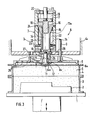
- Figure 3 shows an embodiment of a device solution.
- a model 2 sits on a plate 1 that can be raised and lowered, and a molding box 3 surrounding it, onto which a filling frame 4 is placed.
- Molding box 3 and filling frame 4 are conventionally prior to compression with molding material, for.
- a compression unit Arranged above this molding unit is a compression unit, generally designated 6, which essentially consists of a pressure cylinder 7 and a press plate 8.
- the pressing plate 8 has a peripheral edge 8a drawn downwards and is guided in the stationary part 6a of the compression unit 6 by means of guide rods 9.
- the press plate 8 is further guided at its center on a pin 10 by means of an extension 8b and axially movable on it to a limited extent, a collar 11 arranged at the end of the guide pin 10 serving as the limit stop and having the bottom 12 of a recess 12a in the press plate 8 cooperates.
- the guide pin 10 sits on the piston rod 13 of a drive piston 15, which - like the piston rod 13 - is provided with a cylindrical cavity 14.
- the piston rod 13 and the piston 15 represent the lower limit of a cylinder space 16, which serves as a gas pressure accumulator.
- the upper limit of the volume of the gas pressure accumulator 16 is formed by an actuating piston 17 which projects with an extension 18 into the cylindrical space 14 of the piston 15.
- the actuating piston 17 in turn delimits a pressure chamber 19 which is acted upon hydraulically via an opening 20.
- On the piston 17 also engages a shift rod 21 which passes through the upper cover of the pressure cylinder 7.
- a hydraulic chamber 22 is delimited by the drive piston 15, the piston rod 13, the pressure cylinder 7 and the lower cylinder cover and can be acted upon by hydraulic oil via connections 23 which also serve as a drain.
- the gas pressure accumulator 16 can be connected via connections 24 to one or more further gas pressure accumulators of constant volume can be used to track Lekageluft or as gas volumes that can be switched on and off to change the overall stroke.
- the starting position before a compression stroke is shown in FIG.
- the press plate 8 has previously been placed on the surface of the molding material filling 5 together with the molding box 3 and the filling frame 4 by lifting the model plate 1 into its upper position, being on the guide pin 10 until the upper end face 25 stops centric approach 8b on a stop disc 26 of the piston rod 13 has been performed.
- the drive piston 15 is under a gas prestress in the cylinder space 16 and a hydraulic back pressure in the hydraulic space 22.
- the cross section of the outflow 23 is designed so that the outflow speed is in any case above 10 m / s, so that piston speeds between 2 and 20 m / s can be generated.
- the temporal degradation of the gas pressure in the gas pressure accumulator 16, the effective area of the drive piston 15, the piston mass, the mass of the pressure plate 8, the hydraulic drainage capacity and the mold box area and the height of the compression stroke determine the compression speed and thus the compression result.
- the drive piston 15 Before reaching its end position, the drive piston 15 is braked.
- the piston rod 13 has a conical extension 13a at its upper end.
- a damping ring 7a is in the lower end of the cylinder 7 used, through the opening 7b, the piston rod 13 engages.
- the cross section of the annular space present between the piston rod 13 and the wall of the opening 7b is appreciably larger than the cross section of the outlets 23. As soon as the extension 13a on the piston rod 13 begins to dip into the opening 7b, the cross section thereof narrows increasingly, so that the hydraulic fluid is throttled until the drive piston finally stops.
- the limited displaceability of the press plate 8 on the guide pin 10 leads to a free stroke, which is indicated by 27 in FIG. In this way, fluctuating properties of the molding material and the associated different compression strokes can be automatically compensated. If the working piston 15 has reached its end position, the pressure plate 8 will continue to move due to its inertia up to the end position, which is determined by the fluidity of the molding material particles still present, and will also produce an additional compression effect on the back of the mold.
- the pressure plate 8 Since air can be trapped within the molding column and below the pressure plate 8 at high compression speeds, the pressure plate 8 is provided with slots, holes or nozzles 28 to avoid shape errors.
- the volume of the gas pressure accumulator 16 which also includes the volume of the cylindrical cavity 14, which is provided for reasons of weight saving, can be adjusted via the actuating piston 17. This allows the output pressure and thus the initial acceleration of the working piston to be varied. The final pressure remains constant regardless of the arrangement of the control piston 17 with a constant piston stroke. The timing of the acceleration can, however, as already indicated, vary by connecting external gas storage via the connections 24. These additional gas accumulators are compressed again to their initial pressure when the working piston 15 is reset by means of the hydraulic medium.
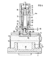
- FIG. 4 an embodiment is shown, the adjustment of the compression stroke, for. B. to adapt to different model geometries.
- a damping sleeve 29 is arranged, which is offset from the pressure cylinder 7 by an annular space 30 on part of its outer surface.
- the damping sleeve 29 is also provided with a plurality of openings 31 which establish the connection between the hydraulic space and the connections 23.
- the damping sleeve 29 can be axially raised and adjusted via a hydraulic system acting on its underside with a connection 32, while the lowering takes place in the hydraulic chamber 22 by the hydraulic fluid.
- the stroke length of the damping sleeve 29 should be approximately 20 to 30% of the compression stroke.
- the molding material is first pre-accelerated below the additional pressure plate mass 35 until finally the remaining lower surface of the pressure plate runs onto the molding material back. The entire molding material mass is then accelerated further.
- the pressure plate 8 and the additional pressure plate mass 35 will each continue to run into their respective end positions independently of one another and depending on the compression of the molding material that is achieved in some areas.
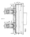
- Figure 6 shows a variant which is particularly suitable for larger molded boxes.
- Two compression units 6, each with a press plate 8 are arranged next to one another on a common carrier 39, each press plate 8 covering approximately half the cross section of the molding box 3 or the filling frame 4.
- the compression stroke of the two compression units 6 can be triggered together, but does not require an exact synchronization movement.
- the switching elements that control the outflow of the hydraulic medium from the hydraulic chamber 22 of the pressure cylinder 7 are expediently arranged in parallel and a pressure compensation line is provided in front of the switching elements.
- the variant according to FIG. 6 can also be modified in such a way that the upper and lower boxes of a complete box shape can be produced in a single work cycle.
- FIG. 5 shows an advantageous exemplary embodiment of the hydraulic control.
- the connections 23 are in a hydraulic high-pressure circuit, the source of which, for. B. a hydraulic pump, designated 41. It is fed from a tank 46. From the high-pressure source 41, the pressure medium passes through a control slide 42 and a check valve 43 into branch lines 44, which lead the pressure medium to the lead both connections 23 of the hydraulic chamber 22.
- the branch lines 44 are connected via a controllable check valve 45 to an outlet tank 47, the outlet 48 of which opens into the tank 46 and which also has a vent 50.
- the check valve 45 is connected to the control slide 42 via a control line 49 and can therefore be acted upon by the hydraulic pump 41. If necessary, the hydraulic chamber 22 can also be connected to the branch lines 44 via a line 51 and a throttle 52 for fine adjustment.
- FIG. 7 finally shows an embodiment of a compression unit 6 with an inductive drive.
- a coil former 54 with a plurality of axially one above the other, Separately excitable and controllable coils 55, 56, 57 and 58 are arranged. Furthermore, a stabilizing and holding coil 59 is present above the coil package 55 to 58.
- the press plate 8 is fastened by means of rods 60 to a coil core 61 which is penetrated by the piston rod 62 with a terminal driver 63 of a log cylinder 64.
- the cylindrical coils 55 to 59 generate a homogeneous, directed electromagnetic force field which automatically aligns the coil core 41 in the rest position, as well as during the movement.
- the compression stroke can be changed in stages by the number of coils 55 to 58 connected.
- the course of acceleration is influenced by the field strength acting on the coil core 61 and, for a given dimension, depends on the current strength within the saturation range of the material of the coil core.
- the compression result can thus be varied not only by varying the compression stroke, but also by changing the current strength of the coils.
- the press plate 8 After compression has taken place, the press plate 8 is brought back into its starting position by means of the remindholzyl Indian 64 and fixed by activating the retention coil 59. Before each compression stroke, the piston rod 62 is extended to the position shown in FIG. 7.
Landscapes
- Engineering & Computer Science (AREA)
- Mechanical Engineering (AREA)
- Casting Devices For Molds (AREA)
- Press Drives And Press Lines (AREA)
- Control Of Presses (AREA)
Applications Claiming Priority (2)
| Application Number | Priority Date | Filing Date | Title |
|---|---|---|---|
| DE3406466A DE3406466A1 (de) | 1984-02-23 | 1984-02-23 | Verfahren und vorrichtung zum verdichten von giessereiformstoff |
| DE3406466 | 1984-02-23 |
Publications (3)
| Publication Number | Publication Date |
|---|---|
| EP0152928A2 true EP0152928A2 (fr) | 1985-08-28 |
| EP0152928A3 EP0152928A3 (en) | 1986-06-04 |
| EP0152928B1 EP0152928B1 (fr) | 1988-01-20 |
Family
ID=6228536
Family Applications (1)
| Application Number | Title | Priority Date | Filing Date |
|---|---|---|---|
| EP85101687A Expired EP0152928B1 (fr) | 1984-02-23 | 1985-02-15 | Procédé et installation de serrage de matière de moulage de fonderie |
Country Status (5)
| Country | Link |
|---|---|
| US (1) | US4617978A (fr) |
| EP (1) | EP0152928B1 (fr) |
| JP (1) | JPH078411B2 (fr) |
| DD (1) | DD235197A5 (fr) |
| DE (2) | DE3406466A1 (fr) |
Cited By (1)
| Publication number | Priority date | Publication date | Assignee | Title |
|---|---|---|---|---|
| GB2199523A (en) * | 1986-11-25 | 1988-07-13 | Doyle Ltd C F | Compacting a moulding mixture by a pressurised gas wave |
Families Citing this family (7)
| Publication number | Priority date | Publication date | Assignee | Title |
|---|---|---|---|---|
| CH672270A5 (fr) * | 1986-12-17 | 1989-11-15 | Fischer Ag Georg | |
| DE3740185A1 (de) * | 1987-06-13 | 1989-06-08 | Badische Maschf Gmbh | Verfahren und vorrichtung zum verdichten von formstoff in giesserei-formmaschinen |
| DE3719846A1 (de) * | 1987-06-13 | 1988-12-22 | Badische Maschf Gmbh | Verfahren und vorrichtung zum verdichten von formstoff in giesserei-formmaschinen |
| US5070928A (en) * | 1990-02-28 | 1991-12-10 | General Motors Corporation | Forming press with quick-change tool-to-bolster locking mechanism |
| CH686412A5 (de) * | 1992-03-10 | 1996-03-29 | Fischer Georg Giessereianlagen | Verfahren zum Verdichten von Formsand fuer Giessformen. |
| US5535809A (en) * | 1993-11-24 | 1996-07-16 | Grand Haven Brass Foundry | Method and apparatus for packing a granular material for foundry use |
| AU2000232748A1 (en) * | 2000-03-20 | 2001-10-03 | Georg Fischer Disa A/S | Method and apparatus for producing two-part moulds |
Family Cites Families (5)
| Publication number | Priority date | Publication date | Assignee | Title |
|---|---|---|---|---|
| US3233291A (en) * | 1960-09-26 | 1966-02-08 | Osborn Mfg Co | Explosive force molding machine and method |
| DE7602966U1 (de) * | 1976-02-03 | 1976-06-24 | Badische Maschinenfabrik Gmbh, 7500 Karlsruhe | Giesserei-formmaschine fuer kastenformen |
| DE2844464C2 (de) * | 1978-10-12 | 1983-03-24 | Bühler, Eugen, Dipl.-Ing., 8871 Burtenbach | Verfahren und Vorrichtung zum Verdichten von Gießformen |
| JPS55120450A (en) * | 1979-03-08 | 1980-09-16 | Sintokogio Ltd | Mold molding apparatus |
| DE3002702C2 (de) * | 1980-01-25 | 1983-09-22 | Alfelder Maschinen- und Modell-Fabrik Künkel, Wagner & Co KG, 3220 Alfeld | Vorrichtung zum Zuführen des Formsandes in den in einer Sandformmaschine in Bereitschaft gehaltenen Formkasten |
-
1984
- 1984-02-23 DE DE3406466A patent/DE3406466A1/de active Granted
-
1985
- 1985-02-15 DE DE8585101687T patent/DE3561444D1/de not_active Expired
- 1985-02-15 EP EP85101687A patent/EP0152928B1/fr not_active Expired
- 1985-02-22 DD DD85273482A patent/DD235197A5/de unknown
- 1985-02-23 JP JP60035192A patent/JPH078411B2/ja not_active Expired - Lifetime
- 1985-02-25 US US06/704,774 patent/US4617978A/en not_active Expired - Lifetime
Cited By (1)
| Publication number | Priority date | Publication date | Assignee | Title |
|---|---|---|---|---|
| GB2199523A (en) * | 1986-11-25 | 1988-07-13 | Doyle Ltd C F | Compacting a moulding mixture by a pressurised gas wave |
Also Published As
| Publication number | Publication date |
|---|---|
| DE3406466A1 (de) | 1985-08-29 |
| JPH078411B2 (ja) | 1995-02-01 |
| JPS60255237A (ja) | 1985-12-16 |
| DE3406466C2 (fr) | 1989-02-02 |
| DD235197A5 (de) | 1986-04-30 |
| EP0152928A3 (en) | 1986-06-04 |
| US4617978A (en) | 1986-10-21 |
| EP0152928B1 (fr) | 1988-01-20 |
| DE3561444D1 (en) | 1988-02-25 |
Similar Documents
| Publication | Publication Date | Title |
|---|---|---|
| DE2819167A1 (de) | Verfahren zur herstellung eines werkstueckes durch fliesspressen, anwendung des verfahrens und vorrichtung zur durchfuehrung des verfahrens | |
| DE3909757A1 (de) | Presse mit einem in die presse einsetzbaren werkzeuggestell | |
| EP0152928B1 (fr) | Procédé et installation de serrage de matière de moulage de fonderie | |
| EP2280178A1 (fr) | Dispositif et méthode de contôle pour un ensemble piston-cylindre | |
| EP0170765A1 (fr) | Dispositif pour comprimer du matériel de moulage pour fonderies | |
| EP0127069B1 (fr) | Dispositif pour serrer le sable de fonderie en procédant par pression de gaz | |
| DE3014068A1 (de) | Verfahren zur herstellung feuerfester steine | |
| EP0185951B1 (fr) | Presse pour compacter de la poudre métallique | |
| EP0417753B1 (fr) | Presse mécanique ou hydraulique avec dispositif d'étirage ou d'emboutissage pour presse à plusieurs étapes | |
| EP0131723B1 (fr) | Dispositif pour le serrage de matière de moulage de fonderie à l'aide de gaz comprimé | |
| EP0139119B2 (fr) | Procédé et installation pour la compression de matériaux de moulage en forme de grain, par exemple sable de fonderie | |
| DE3532190C2 (fr) | ||
| EP1053801B1 (fr) | Dispositif de fermeture hydraulique pour l'extrusion latérale de pièces | |
| DE2165929B2 (de) | Einrichtung zum beschleunigten aufbau und zur regulierung des nachdruckes an druckgiessmaschinen, insbesondere kaltkammer-druckgiessmaschinen | |
| DE3518980C2 (fr) | ||
| EP0152573B1 (fr) | Dispositif pour compacter du matériau de moulage de fonderie à l'aide d'un gaz de compression | |
| DE3123498C1 (de) | Vorrichtung zum beschleunigten Aufbau und zur Regulierung des Nachdruckes an Druckgiessmaschinen | |
| EP1155761A1 (fr) | Procédé et dispositif pour la densification de matériaux de moulage p.e. sable de moulage | |
| DE4028920A1 (de) | Mechanische oder hydraulische presse mit zieheinrichtung oder ziehstufe einer stufenpresse | |
| EP0262519A2 (fr) | Procédé et dispositif pour l'amortissement de la pointe de pression à la fin de la phase de remplissage du moule des machines à couler sous pression | |
| DE3904617A1 (de) | Presse zum kaltformen von formmassen zu formkoerpern, insbesondere keramischen steinen | |
| DE2701693A1 (de) | Formmaschine zur herstellung von giessformhaelften in formkaesten | |
| DE19545753B4 (de) | Regelung von Rahmenposition und Preßdruck in Formanlagen | |
| DE3801497A1 (de) | Schiesskopf fuer eine saug-press-formmaschine und verfahren zu deren betrieb | |
| AT268010B (de) | Auswerfereinrichtung für Schlagverformungsmaschinen |
Legal Events
| Date | Code | Title | Description |
|---|---|---|---|
| PUAI | Public reference made under article 153(3) epc to a published international application that has entered the european phase |
Free format text: ORIGINAL CODE: 0009012 |
|
| AK | Designated contracting states |
Designated state(s): CH DE FR GB LI |
|
| PUAL | Search report despatched |
Free format text: ORIGINAL CODE: 0009013 |
|
| AK | Designated contracting states |
Kind code of ref document: A3 Designated state(s): CH DE FR GB LI |
|
| 17P | Request for examination filed |
Effective date: 19860524 |
|
| 17Q | First examination report despatched |
Effective date: 19861016 |
|
| GRAA | (expected) grant |
Free format text: ORIGINAL CODE: 0009210 |
|
| AK | Designated contracting states |
Kind code of ref document: B1 Designated state(s): CH DE FR GB LI |
|
| REF | Corresponds to: |
Ref document number: 3561444 Country of ref document: DE Date of ref document: 19880225 |
|
| ET | Fr: translation filed | ||
| GBT | Gb: translation of ep patent filed (gb section 77(6)(a)/1977) | ||
| PLBE | No opposition filed within time limit |
Free format text: ORIGINAL CODE: 0009261 |
|
| STAA | Information on the status of an ep patent application or granted ep patent |
Free format text: STATUS: NO OPPOSITION FILED WITHIN TIME LIMIT |
|
| 26N | No opposition filed | ||
| PGFP | Annual fee paid to national office [announced via postgrant information from national office to epo] |
Ref country code: FR Payment date: 19980127 Year of fee payment: 14 |
|
| PGFP | Annual fee paid to national office [announced via postgrant information from national office to epo] |
Ref country code: GB Payment date: 19980205 Year of fee payment: 14 |
|
| PGFP | Annual fee paid to national office [announced via postgrant information from national office to epo] |
Ref country code: DE Payment date: 19980225 Year of fee payment: 14 |
|
| PG25 | Lapsed in a contracting state [announced via postgrant information from national office to epo] |
Ref country code: GB Free format text: LAPSE BECAUSE OF NON-PAYMENT OF DUE FEES Effective date: 19990215 |
|
| PGFP | Annual fee paid to national office [announced via postgrant information from national office to epo] |
Ref country code: CH Payment date: 19990316 Year of fee payment: 15 |
|
| PG25 | Lapsed in a contracting state [announced via postgrant information from national office to epo] |
Ref country code: DE Free format text: LAPSE BECAUSE OF THE APPLICANT RENOUNCES Effective date: 19990506 |
|
| GBPC | Gb: european patent ceased through non-payment of renewal fee |
Effective date: 19990215 |
|
| PG25 | Lapsed in a contracting state [announced via postgrant information from national office to epo] |
Ref country code: FR Free format text: LAPSE BECAUSE OF NON-PAYMENT OF DUE FEES Effective date: 19991029 |
|
| REG | Reference to a national code |
Ref country code: FR Ref legal event code: ST |
|
| PG25 | Lapsed in a contracting state [announced via postgrant information from national office to epo] |
Ref country code: CH Free format text: LAPSE BECAUSE OF NON-PAYMENT OF DUE FEES Effective date: 20000229 Ref country code: LI Free format text: LAPSE BECAUSE OF NON-PAYMENT OF DUE FEES Effective date: 20000229 |
|
| REG | Reference to a national code |
Ref country code: CH Ref legal event code: PL |