EP0152936B1 - Entraînement rotatif mécanique - Google Patents
Entraînement rotatif mécanique Download PDFInfo
- Publication number
- EP0152936B1 EP0152936B1 EP85101722A EP85101722A EP0152936B1 EP 0152936 B1 EP0152936 B1 EP 0152936B1 EP 85101722 A EP85101722 A EP 85101722A EP 85101722 A EP85101722 A EP 85101722A EP 0152936 B1 EP0152936 B1 EP 0152936B1
- Authority
- EP
- European Patent Office
- Prior art keywords
- drive
- output
- transmissions
- preloading
- input shaft
- Prior art date
- Legal status (The legal status is an assumption and is not a legal conclusion. Google has not performed a legal analysis and makes no representation as to the accuracy of the status listed.)
- Expired
Links
Images
Classifications
-
- B—PERFORMING OPERATIONS; TRANSPORTING
- B25—HAND TOOLS; PORTABLE POWER-DRIVEN TOOLS; MANIPULATORS
- B25J—MANIPULATORS; CHAMBERS PROVIDED WITH MANIPULATION DEVICES
- B25J17/00—Joints
- B25J17/02—Wrist joints
- B25J17/0241—One-dimensional joints
-
- B—PERFORMING OPERATIONS; TRANSPORTING
- B25—HAND TOOLS; PORTABLE POWER-DRIVEN TOOLS; MANIPULATORS
- B25J—MANIPULATORS; CHAMBERS PROVIDED WITH MANIPULATION DEVICES
- B25J9/00—Program-controlled manipulators
- B25J9/10—Program-controlled manipulators characterised by positioning means for manipulator elements
- B25J9/102—Gears specially adapted therefor, e.g. reduction gears
- B25J9/1025—Harmonic drives
-
- F—MECHANICAL ENGINEERING; LIGHTING; HEATING; WEAPONS; BLASTING
- F16—ENGINEERING ELEMENTS AND UNITS; GENERAL MEASURES FOR PRODUCING AND MAINTAINING EFFECTIVE FUNCTIONING OF MACHINES OR INSTALLATIONS; THERMAL INSULATION IN GENERAL
- F16H—GEARING
- F16H49/00—Other gearings
- F16H49/001—Wave gearings, e.g. harmonic drive transmissions
-
- Y—GENERAL TAGGING OF NEW TECHNOLOGICAL DEVELOPMENTS; GENERAL TAGGING OF CROSS-SECTIONAL TECHNOLOGIES SPANNING OVER SEVERAL SECTIONS OF THE IPC; TECHNICAL SUBJECTS COVERED BY FORMER USPC CROSS-REFERENCE ART COLLECTIONS [XRACs] AND DIGESTS
- Y10—TECHNICAL SUBJECTS COVERED BY FORMER USPC
- Y10T—TECHNICAL SUBJECTS COVERED BY FORMER US CLASSIFICATION
- Y10T74/00—Machine element or mechanism
- Y10T74/19—Gearing
Definitions
- the invention relates to a mechanical rotary drive, preferably a reduction drive, in particular for industrial robots, for example a manipulator arm rotary drive, with a drive and an output side, a drive shaft and at least two gears which are coupled to one another and arranged thereon, braced against one another, preferably reduction gears, on their output side are coupled to the output element.
- a mechanical rotary drive preferably a reduction drive, in particular for industrial robots, for example a manipulator arm rotary drive, with a drive and an output side, a drive shaft and at least two gears which are coupled to one another and arranged thereon, braced against one another, preferably reduction gears, on their output side are coupled to the output element.
- the gears are torsionally elastic connected on the drive side in order to achieve a gear reduction that is as free of play as possible and on the output side directly connected to the manipulator arm that can be rotated by the gear, the torsionally rigid is carried out, so that there is overall a torsionally rigid coupling of the reduction gears on the output side.
- the torsionally elastic coupling of the gears on the drive side of the rotary drive is associated with the disadvantage that, in particular when the rotary drive is driven on one side, movement uniformities occur as a function of the direction of rotation, which lead to undesirably large fluctuations in terms of positioning accuracy.
- the invention is therefore based on the object of specifying a mechanical rotary drive, in particular for an industrial robot, with which a high positioning accuracy can be achieved, but which is nevertheless structurally simple as possible and also inexpensive to manufacture.
- the above-mentioned object is initially essentially achieved in that the drive-side clutch is torsionally rigid and the transmission bracing is carried out on the output side via a torsionally elastic coupling between the transmission output sides and the output element.
- the measure according to the invention of designing the transmission bracing on the output side to be torsionally elastic leads to the surprising advantage that structurally very simple measures lead to the desired result.
- a symmetrical delivery of the torque introduced on the drive side is no longer problematic, since the torque is divided on the drive side and the same torque is applied to the two reduction gears on the output side, with practically the same rotation angles of the drive shaft regardless of the direction of rotation of the drive shaft. Since there are no special requirements to be met by the drive shaft with the exception of the torsional rigidity, a machine part that is simple in terms of material and production, and therefore inexpensive, can be used as the drive shaft.
- the drive shaft is acted upon on one side by a drive torque.
- a drive motor connected to the drive shaft on one side can be provided, or the torque can be introduced via a power transmission by means of a toothed belt, for which purpose a corresponding drive pinion is also provided on the drive shaft.
- Harmonic drive transmissions are known as such in the prior art, for which purpose reference is only made, for example, to “Gear Handbook”, 1st Edition, McGraw-Hill Book Company, Inc., 1962, pages 3-35 to 3-44.
- Such essential harmonic drive gears have an internally toothed rigid ring (circular spline), an externally toothed flexible cylinder (flexspline) and an elliptical inner body.
- the output side the flexspline be held and the circular spline can move, as can the circular spline and the flexspline can move.
- the circular spline is preferably held and the output torque is removed on the flexspline. This utilizes the property of the harmonic drive transmission that the flexspline, which is designed as a flexible component due to the nature of the transmission, provides a torsionally elastic element.
- the reduction gears can be braced in a simple manner by rotating the drive wheels or the elliptical inner bodies on the drive shaft. Special measures for bracing the gears against each other are therefore not necessary.
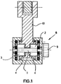
- a mechanical rotary drive generally designated 8, with which, in the exemplary embodiment shown, a manipulator arm 10 is rotated by means of a torque applied via a drive motor 9 via the reduction gears 2 and 3.
- the reduction gears 2, 3 are torsionally stiff and on the output side via the hollow shafts 6 are torsionally elastic, so that the advantages explained in more detail above result in the tensioned state.
- the drive shaft 1 is a simple series component which is only characterized by a high torsional rigidity.
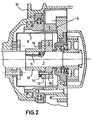
- the reduction gears 2 and 3 are designed as harmonic drive gears 4, which as essential elements are an internally toothed ring or circular spline 5, an externally toothed flexible cylinder or flexspline 6 and an elliptical inner body 7.
- the flexspline 6 is used for the transmission of the torques on the output side, which results in the described torsional elastic coupling between the manipulator arm 10 and the harmonic transmission 4.
- the elliptical inner body 7 can be rotated on the drive shaft 1 and locked in any position against a stationary sleeve 12 provided on the drive shaft 1 by means of a feather key 11, so that the mentioned bracing of the reduction gears 2, 3 against one another can be carried out in a simple manner.
- a hub 13 of the locking sleeve 12 is provided with, for example, two circular-shaped elongated holes 14, and a clamping disk 15 is additionally provided, with the aid of which the locking sleeve 12 or the hub 13 of the locking sleeve 12 is frictionally engaged with the help of approximately one Bracing screw 16 can be held relative to the elliptical inner body 7.
Landscapes
- Engineering & Computer Science (AREA)
- Mechanical Engineering (AREA)
- General Engineering & Computer Science (AREA)
- Robotics (AREA)
- Retarders (AREA)
- Manipulator (AREA)
- Gear Transmission (AREA)
- Valve Device For Special Equipments (AREA)
- Surgical Instruments (AREA)
- Transmission Devices (AREA)
Claims (5)
Priority Applications (1)
| Application Number | Priority Date | Filing Date | Title |
|---|---|---|---|
| AT85101722T ATE35725T1 (de) | 1984-02-21 | 1985-02-16 | Mechanischer drehantrieb. |
Applications Claiming Priority (2)
| Application Number | Priority Date | Filing Date | Title |
|---|---|---|---|
| DE3406262 | 1984-02-21 | ||
| DE19843406262 DE3406262A1 (de) | 1984-02-21 | 1984-02-21 | Mechanischer drehantrieb |
Publications (2)
| Publication Number | Publication Date |
|---|---|
| EP0152936A1 EP0152936A1 (fr) | 1985-08-28 |
| EP0152936B1 true EP0152936B1 (fr) | 1988-07-13 |
Family
ID=6228406
Family Applications (1)
| Application Number | Title | Priority Date | Filing Date |
|---|---|---|---|
| EP85101722A Expired EP0152936B1 (fr) | 1984-02-21 | 1985-02-16 | Entraînement rotatif mécanique |
Country Status (7)
| Country | Link |
|---|---|
| US (1) | US4770059A (fr) |
| EP (1) | EP0152936B1 (fr) |
| JP (1) | JPS6159043A (fr) |
| AT (1) | ATE35725T1 (fr) |
| DE (2) | DE3406262A1 (fr) |
| SU (1) | SU1478999A3 (fr) |
| WO (1) | WO1985003753A1 (fr) |
Families Citing this family (14)
| Publication number | Priority date | Publication date | Assignee | Title |
|---|---|---|---|---|
| US4973215A (en) * | 1986-02-18 | 1990-11-27 | Robotics Research Corporation | Industrial robot with servo |
| JPS63180751A (ja) * | 1987-01-19 | 1988-07-25 | Mitsubishi Electric Corp | 調和減速機 |
| JP3768261B2 (ja) * | 1995-05-19 | 2006-04-19 | 株式会社ハーモニック・ドライブ・システムズ | 偏平型波動歯車装置 |
| JPH0989053A (ja) * | 1995-09-29 | 1997-03-31 | Harmonic Drive Syst Ind Co Ltd | 波動歯車装置 |
| JP3585008B2 (ja) * | 1996-02-15 | 2004-11-04 | 株式会社ハーモニック・ドライブ・システムズ | 密閉型波動歯車装置 |
| JP2000009191A (ja) | 1998-06-19 | 2000-01-11 | Harmonic Drive Syst Ind Co Ltd | カップ型波動歯車装置 |
| DE19835571A1 (de) * | 1998-08-06 | 2000-02-17 | Ims Morat Soehne Gmbh | Wellgetriebe und Verfahren zu dessen Zahnoptimierung |
| JP2002243000A (ja) * | 2001-02-19 | 2002-08-28 | Harmonic Drive Syst Ind Co Ltd | 波動歯車減速機を備えたアクチュエータ |
| JP4737695B2 (ja) * | 2005-12-20 | 2011-08-03 | 株式会社ハーモニック・ドライブ・システムズ | 指関節機構 |
| CN105358870B (zh) * | 2013-07-04 | 2017-12-05 | 谐波传动系统有限公司 | 将被驱动构件紧固于波动齿轮装置单元的紧固方法及波动齿轮装置单元 |
| CN103486225B (zh) * | 2013-09-25 | 2015-12-02 | 深圳先进技术研究院 | 具有力矩感知功能的谐波减速器 |
| WO2017041800A1 (fr) * | 2015-09-10 | 2017-03-16 | Schaeffler Technologies AG & Co. KG | Transmission à roue dentée élastique |
| DE102016223474B3 (de) * | 2016-11-25 | 2018-03-08 | Schaeffler Technologies AG & Co. KG | Verstellgetriebevorrichtung für eine Welle sowie Fahrzeug mit der Verstellgetriebevorrichtung |
| CN112743567B (zh) * | 2020-12-28 | 2022-05-17 | 深圳市优必选科技股份有限公司 | 舵机模组及机器人 |
Citations (1)
| Publication number | Priority date | Publication date | Assignee | Title |
|---|---|---|---|---|
| DE3115061A1 (de) * | 1980-05-29 | 1982-02-04 | Industrie-Werke Karlsruhe Augsburg AG Zweigniederlassung Keller & Knappich Augsburg, 8900 Augsburg | Schwenkantrieb fuer schwenkbar gelagerte maschinenteile, insbesondere bei manipulatoren |
Family Cites Families (8)
| Publication number | Priority date | Publication date | Assignee | Title |
|---|---|---|---|---|
| US3214999A (en) * | 1964-04-09 | 1965-11-02 | Roger H Lapp | Harmonic drive |
| US3482770A (en) * | 1968-04-10 | 1969-12-09 | Laval Separator Co De | Variable speed power transmission |
| US3555929A (en) * | 1968-08-02 | 1971-01-19 | Usm Corp | Extended root flexsplines |
| FR2314390A1 (fr) * | 1975-06-13 | 1977-01-07 | Sofermo | Articulation modulaire autonome pour mecanismes divers et en particulier pour robots |
| JPS6039518B2 (ja) * | 1980-09-30 | 1985-09-06 | ファナック株式会社 | 工業用ロボットの手首機構 |
| US4518308A (en) * | 1982-03-01 | 1985-05-21 | Acrobe Technology Inc. | Manipulator apparatus |
| JPS58211892A (ja) * | 1982-05-31 | 1983-12-09 | 松下電器産業株式会社 | 工業用ロボツト |
| DE3308413C1 (de) * | 1983-03-09 | 1984-10-04 | Kuka Schweissanlagen + Roboter Gmbh, 8900 Augsburg | Spielfrei einstellbarer Schwenkantrieb fuer mindestens eine Hauptachse von Manipulatoren |
-
1984
- 1984-02-21 DE DE19843406262 patent/DE3406262A1/de active Granted
-
1985
- 1985-02-16 AT AT85101722T patent/ATE35725T1/de not_active IP Right Cessation
- 1985-02-16 DE DE8585101722T patent/DE3563781D1/de not_active Expired
- 1985-02-16 EP EP85101722A patent/EP0152936B1/fr not_active Expired
- 1985-02-20 JP JP60033609A patent/JPS6159043A/ja active Pending
- 1985-02-21 US US06/798,890 patent/US4770059A/en not_active Expired - Fee Related
- 1985-02-21 WO PCT/DE1985/000050 patent/WO1985003753A1/fr not_active Ceased
- 1985-10-11 SU SU853970610A patent/SU1478999A3/ru active
Patent Citations (1)
| Publication number | Priority date | Publication date | Assignee | Title |
|---|---|---|---|---|
| DE3115061A1 (de) * | 1980-05-29 | 1982-02-04 | Industrie-Werke Karlsruhe Augsburg AG Zweigniederlassung Keller & Knappich Augsburg, 8900 Augsburg | Schwenkantrieb fuer schwenkbar gelagerte maschinenteile, insbesondere bei manipulatoren |
Also Published As
| Publication number | Publication date |
|---|---|
| SU1478999A3 (ru) | 1989-05-07 |
| DE3406262A1 (de) | 1985-09-05 |
| EP0152936A1 (fr) | 1985-08-28 |
| US4770059A (en) | 1988-09-13 |
| WO1985003753A1 (fr) | 1985-08-29 |
| DE3563781D1 (en) | 1988-08-18 |
| JPS6159043A (ja) | 1986-03-26 |
| ATE35725T1 (de) | 1988-07-15 |
| DE3406262C2 (fr) | 1987-11-12 |
Similar Documents
| Publication | Publication Date | Title |
|---|---|---|
| EP0152936B1 (fr) | Entraînement rotatif mécanique | |
| EP2666600B1 (fr) | Robot industriel doté d'entraînements s'étendant dans un boîtier de base manuel | |
| DE2751579C2 (de) | Motorgetriebener Manipulator | |
| DE3441332C2 (fr) | ||
| DE69601213T2 (de) | Handgelenk für industrieroboter | |
| EP0021223B1 (fr) | Engrenage avec compensation de forces axiales | |
| WO2003106114A1 (fr) | Manipulateur parallele comportant des engrenages sans jeu | |
| DE69206072T2 (de) | Zykloidengetriebe. | |
| DE2539029A1 (de) | Getriebe zur verwendung als kraftuebertragungskupplung | |
| DE102014109490B4 (de) | Handgelenkskonstruktion für einen Industrieroboter | |
| DE69512525T2 (de) | Antriebseinheit für einen industrieroboter | |
| DE3130518C2 (de) | Steuer- und Antriebsvorrichtung, bestehend aus einem Planetengetriebe und einem mit diesem verbundenen Antrieb | |
| DE112022000154T5 (de) | Beschleunigungsmechanismus für einen SCARA-Roboter und SCARA-Roboter mit einem derartigen Beschleunigungsmechanismus | |
| DE19534063C2 (de) | Winkelmeßeinrichtung | |
| DE3513056A1 (de) | Gelenk-antriebsanordnung | |
| DE102021124205A1 (de) | Untersetzungsvorrichtung und Antrieb | |
| DE3530365A1 (de) | Handgelenk fuer industrieroboter | |
| DE102024121420A1 (de) | Werkzeugmodul zur Anordnung an ein Robotersystem und Robotersystem | |
| DE102020113426A1 (de) | Parallelroboter | |
| DE60301648T2 (de) | Antriebsvorrichtung für Werkzeugmaschinen | |
| DE29812177U1 (de) | Antriebsaggregat, insbesondere Schließbolzen-Antriebsaggregat | |
| EP3833891A1 (fr) | Engrenage à crémaillère à étages multiples | |
| DE3704951A1 (de) | Antriebsmodul fuer arbeitsgelenke von industrierobotern | |
| EP0100810A2 (fr) | Réducteur de vitesse | |
| DE19512996C2 (de) | Drehwerksantrieb mit einem Motor, einem Planetengetriebe und einem Drehwerksritzel |
Legal Events
| Date | Code | Title | Description |
|---|---|---|---|
| PUAI | Public reference made under article 153(3) epc to a published international application that has entered the european phase |
Free format text: ORIGINAL CODE: 0009012 |
|
| AK | Designated contracting states |
Designated state(s): AT BE CH DE FR GB IT LI NL SE |
|
| RAP1 | Party data changed (applicant data changed or rights of an application transferred) |
Owner name: EKE ROBOTERSYSTEME GMBH |
|
| 17P | Request for examination filed |
Effective date: 19860131 |
|
| 17Q | First examination report despatched |
Effective date: 19870410 |
|
| GRAA | (expected) grant |
Free format text: ORIGINAL CODE: 0009210 |
|
| ITF | It: translation for a ep patent filed | ||
| AK | Designated contracting states |
Kind code of ref document: B1 Designated state(s): AT BE CH DE FR GB IT LI NL SE |
|
| PG25 | Lapsed in a contracting state [announced via postgrant information from national office to epo] |
Ref country code: NL Effective date: 19880713 Ref country code: BE Effective date: 19880713 |
|
| REF | Corresponds to: |
Ref document number: 35725 Country of ref document: AT Date of ref document: 19880715 Kind code of ref document: T |
|
| GBT | Gb: translation of ep patent filed (gb section 77(6)(a)/1977) | ||
| REF | Corresponds to: |
Ref document number: 3563781 Country of ref document: DE Date of ref document: 19880818 |
|
| ET | Fr: translation filed | ||
| NLV1 | Nl: lapsed or annulled due to failure to fulfill the requirements of art. 29p and 29m of the patents act | ||
| PG25 | Lapsed in a contracting state [announced via postgrant information from national office to epo] |
Ref country code: AT Effective date: 19890216 |
|
| PGFP | Annual fee paid to national office [announced via postgrant information from national office to epo] |
Ref country code: FR Payment date: 19890222 Year of fee payment: 5 |
|
| PGFP | Annual fee paid to national office [announced via postgrant information from national office to epo] |
Ref country code: SE Payment date: 19890227 Year of fee payment: 5 |
|
| ITTA | It: last paid annual fee | ||
| PG25 | Lapsed in a contracting state [announced via postgrant information from national office to epo] |
Ref country code: LI Effective date: 19890228 Ref country code: CH Effective date: 19890228 |
|
| PGFP | Annual fee paid to national office [announced via postgrant information from national office to epo] |
Ref country code: GB Payment date: 19890228 Year of fee payment: 5 |
|
| PGFP | Annual fee paid to national office [announced via postgrant information from national office to epo] |
Ref country code: DE Payment date: 19890323 Year of fee payment: 5 |
|
| PLBE | No opposition filed within time limit |
Free format text: ORIGINAL CODE: 0009261 |
|
| STAA | Information on the status of an ep patent application or granted ep patent |
Free format text: STATUS: NO OPPOSITION FILED WITHIN TIME LIMIT |
|
| 26N | No opposition filed | ||
| REG | Reference to a national code |
Ref country code: CH Ref legal event code: PL |
|
| PG25 | Lapsed in a contracting state [announced via postgrant information from national office to epo] |
Ref country code: GB Effective date: 19900216 |
|
| PG25 | Lapsed in a contracting state [announced via postgrant information from national office to epo] |
Ref country code: SE Effective date: 19900217 |
|
| GBPC | Gb: european patent ceased through non-payment of renewal fee | ||
| PG25 | Lapsed in a contracting state [announced via postgrant information from national office to epo] |
Ref country code: FR Effective date: 19901031 |
|
| PG25 | Lapsed in a contracting state [announced via postgrant information from national office to epo] |
Ref country code: DE Effective date: 19901101 |
|
| REG | Reference to a national code |
Ref country code: FR Ref legal event code: ST |
|
| EUG | Se: european patent has lapsed |
Ref document number: 85101722.8 Effective date: 19901107 |