EP0152980A1 - Faisceau de tuyaux et bâtiment équipé de ce faisceau - Google Patents
Faisceau de tuyaux et bâtiment équipé de ce faisceau Download PDFInfo
- Publication number
- EP0152980A1 EP0152980A1 EP85200126A EP85200126A EP0152980A1 EP 0152980 A1 EP0152980 A1 EP 0152980A1 EP 85200126 A EP85200126 A EP 85200126A EP 85200126 A EP85200126 A EP 85200126A EP 0152980 A1 EP0152980 A1 EP 0152980A1
- Authority
- EP
- European Patent Office
- Prior art keywords
- bundle
- conduits
- duct
- building
- annular
- Prior art date
- Legal status (The legal status is an assumption and is not a legal conclusion. Google has not performed a legal analysis and makes no representation as to the accuracy of the status listed.)
- Withdrawn
Links
- XLYOFNOQVPJJNP-UHFFFAOYSA-N water Substances O XLYOFNOQVPJJNP-UHFFFAOYSA-N 0.000 claims abstract description 5
- 239000012530 fluid Substances 0.000 claims abstract description 3
- 238000005192 partition Methods 0.000 claims description 3
- 230000005611 electricity Effects 0.000 description 2
- 238000010438 heat treatment Methods 0.000 description 2
- 238000000034 method Methods 0.000 description 2
- 238000009423 ventilation Methods 0.000 description 1
Images
Classifications
-
- E—FIXED CONSTRUCTIONS
- E04—BUILDING
- E04B—GENERAL BUILDING CONSTRUCTIONS; WALLS, e.g. PARTITIONS; ROOFS; FLOORS; CEILINGS; INSULATION OR OTHER PROTECTION OF BUILDINGS
- E04B1/00—Constructions in general; Structures which are not restricted either to walls, e.g. partitions, or floors or ceilings or roofs
- E04B1/0023—Building characterised by incorporated canalisations
-
- E—FIXED CONSTRUCTIONS
- E03—WATER SUPPLY; SEWERAGE
- E03C—DOMESTIC PLUMBING INSTALLATIONS FOR FRESH WATER OR WASTE WATER; SINKS
- E03C1/00—Domestic plumbing installations for fresh water or waste water; Sinks
- E03C1/02—Plumbing installations for fresh water
- E03C1/021—Devices for positioning or connecting of water supply lines
- E03C1/023—Devices for positioning or connecting of water supply lines with flow distribution, e.g. diverters
-
- F—MECHANICAL ENGINEERING; LIGHTING; HEATING; WEAPONS; BLASTING
- F16—ENGINEERING ELEMENTS AND UNITS; GENERAL MEASURES FOR PRODUCING AND MAINTAINING EFFECTIVE FUNCTIONING OF MACHINES OR INSTALLATIONS; THERMAL INSULATION IN GENERAL
- F16L—PIPES; JOINTS OR FITTINGS FOR PIPES; SUPPORTS FOR PIPES, CABLES OR PROTECTIVE TUBING; MEANS FOR THERMAL INSULATION IN GENERAL
- F16L3/00—Supports for pipes, cables or protective tubing, e.g. hangers, holders, clamps, cleats, clips, brackets
Definitions
- the invention relates to a bundle of conduits of different kinds for use in a building such as a house, a ship and so on, said bundle comprising inter alia conduits for fluids such as gas and water.
- a building such as a house, a ship and so on
- said bundle comprising inter alia conduits for fluids such as gas and water.
- the invention has for its object to obviate said inconvenience and provides to this end a bundle which is distinguished in that at predetermined areas the bundle is surrounded by an annular, closed duct communicating on the one hand with a similar duct in the bundle and on the other hand with a branch duct or a stub.
- the branch duct can be connected with the bundle at arbitrary areas of the circumference without the need for taking other types of conduits in the bundle into account.
- annular duct It is preferred to previously provide the annular duct with standard connections such as stubs, thinned places for removing wall parts and so on.
- the annular duct can serve.at the same time as a support for covering or ornamental plates to be fixed afterwards.
- the invention furthermore relates to a building such as a house or a ship provided with a prefabricated bundle of conduits of the kind set forth above.
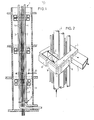
- reference numeral 1 designates the bundle of conduits comprising, for example, an inlet and an outlet conduit 2, 3 for air heating or ventilation, water pipes and electricity conduits 4 and 5 respectively.
- the bundle of conduits is surrounded by an annular duct communicating at each area with the same kind of conduit of the bundle.
- the annular duct 6 is connected with the conduit 2 and the passage thereof is at least half that of the conduit 2.
- the annular duct 6 has a polygonal shape, in this case, for example, a quadrangular shape, the cross-section being rectangular.
- the pace of the branch duct 7 with respect to the inlet conduit 2 in the bundle can be arbitrarily chosen in the "four winds".
- the annular duct 6 may be provided for this purpose with standard connecting points 8, which can be readily broken up.
- the annular duct 6 is connected through a connecting duct 9 with the conduit 2, said duct 9 being connected with the inner side of the annular duct. It will be obvious that also the wall of the conduit 2 can be directly connected with the wall of the duct 6 without the use of an intermediate duct 9.
- the bundle of conduits 1 may be provided with connecting means 10, for example, flanges or sockets, where the connection with the conduits previously provided in the foundation or conduits from a heating system can be established.
- the building may have a shaft 11 into which the bundle of conduits 1 as a whole can be introduced from the top during the mounting operations. Therefore, the bundle of conduits can be prepared in advance in the factory.
- the annular duct 6 may have any desired shape. As stated above, the annular duct 6 of figs. 1 and 2 is polygonal, which is particularly suitable for transporting gas, for example, hot air. Nevertheless the water and electricity conduits may also be coupled with an annular duct 12 with which a branch duct 13 can be suitably connected.
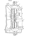
- Fig. 3 shows that the annular duct 6 has the shape of a circle in this case; the branch duct 7' can be connected with the outer face of the duct 6' as well as with the bottom and top sides respectively. Obviously a high degree of freedom is thus obtained without disturbance of the conduits in the bundle 1 by the connections.
- a conduit for example, 14 directly, without annular duct, with a branch stub 15, which can be connected by means of a socket 16 with a branch duct 17.
- a high-pressure tube 18, for example, for vapour provided with a branch stub 19 having a standard connecting flange 20.
- the annular duct of fig. 3 also serve as fastening supports for covering or ornamental plates 21.
Landscapes
- Engineering & Computer Science (AREA)
- General Engineering & Computer Science (AREA)
- Architecture (AREA)
- Health & Medical Sciences (AREA)
- Life Sciences & Earth Sciences (AREA)
- Hydrology & Water Resources (AREA)
- Public Health (AREA)
- Water Supply & Treatment (AREA)
- Physics & Mathematics (AREA)
- Mechanical Engineering (AREA)
- Electromagnetism (AREA)
- Civil Engineering (AREA)
- Structural Engineering (AREA)
- Quick-Acting Or Multi-Walled Pipe Joints (AREA)
- Rigid Pipes And Flexible Pipes (AREA)
Applications Claiming Priority (2)
| Application Number | Priority Date | Filing Date | Title |
|---|---|---|---|
| NL8400348A NL8400348A (nl) | 1984-02-03 | 1984-02-03 | Leidingenbundel, en bouwwerk voorzien van een dergelijke bundel. |
| NL8400348 | 1984-02-03 |
Publications (1)
| Publication Number | Publication Date |
|---|---|
| EP0152980A1 true EP0152980A1 (fr) | 1985-08-28 |
Family
ID=19843427
Family Applications (1)
| Application Number | Title | Priority Date | Filing Date |
|---|---|---|---|
| EP85200126A Withdrawn EP0152980A1 (fr) | 1984-02-03 | 1985-02-01 | Faisceau de tuyaux et bâtiment équipé de ce faisceau |
Country Status (2)
| Country | Link |
|---|---|
| EP (1) | EP0152980A1 (fr) |
| NL (1) | NL8400348A (fr) |
Cited By (2)
| Publication number | Priority date | Publication date | Assignee | Title |
|---|---|---|---|---|
| DE102005021737A1 (de) * | 2005-05-11 | 2006-11-16 | Weber, Werner, Dipl.-Ing. | Verfahren zur flexiblen Grundrissgestaltung von Gewerbegrossflächen im Bereich Gebäudetechnik |
| CN114251518A (zh) * | 2021-12-20 | 2022-03-29 | 陕西建工第三建设集团有限公司 | 一种无层板封闭式管井的管道安装结构及其施工方法 |
Citations (3)
| Publication number | Priority date | Publication date | Assignee | Title |
|---|---|---|---|---|
| US4052090A (en) * | 1976-03-31 | 1977-10-04 | Chicago Bridge & Iron Company | Multiport swivel joint |
| EP0006015A1 (fr) * | 1978-05-31 | 1979-12-12 | Ernest Joseph Kump | Module spatial |
| US4353608A (en) * | 1979-06-21 | 1982-10-12 | Massau Julien G | System of collectors for conduits in a dwelling |
-
1984
- 1984-02-03 NL NL8400348A patent/NL8400348A/nl not_active Application Discontinuation
-
1985
- 1985-02-01 EP EP85200126A patent/EP0152980A1/fr not_active Withdrawn
Patent Citations (3)
| Publication number | Priority date | Publication date | Assignee | Title |
|---|---|---|---|---|
| US4052090A (en) * | 1976-03-31 | 1977-10-04 | Chicago Bridge & Iron Company | Multiport swivel joint |
| EP0006015A1 (fr) * | 1978-05-31 | 1979-12-12 | Ernest Joseph Kump | Module spatial |
| US4353608A (en) * | 1979-06-21 | 1982-10-12 | Massau Julien G | System of collectors for conduits in a dwelling |
Cited By (3)
| Publication number | Priority date | Publication date | Assignee | Title |
|---|---|---|---|---|
| DE102005021737A1 (de) * | 2005-05-11 | 2006-11-16 | Weber, Werner, Dipl.-Ing. | Verfahren zur flexiblen Grundrissgestaltung von Gewerbegrossflächen im Bereich Gebäudetechnik |
| CN114251518A (zh) * | 2021-12-20 | 2022-03-29 | 陕西建工第三建设集团有限公司 | 一种无层板封闭式管井的管道安装结构及其施工方法 |
| CN114251518B (zh) * | 2021-12-20 | 2022-09-27 | 陕西建工第三建设集团有限公司 | 一种无层板封闭式管井的管道安装结构及其施工方法 |
Also Published As
| Publication number | Publication date |
|---|---|
| NL8400348A (nl) | 1985-09-02 |
Similar Documents
| Publication | Publication Date | Title |
|---|---|---|
| US5420376A (en) | Plastic electrical box for installation in poured concrete | |
| US4735235A (en) | Insulated duct end system | |
| JP2001512226A (ja) | 空気調和装置の室内ユニットを接続するための箱 | |
| US3442058A (en) | Concrete floor construction with duct-forming voids | |
| US3202077A (en) | Expansion channel | |
| EP0152980A1 (fr) | Faisceau de tuyaux et bâtiment équipé de ce faisceau | |
| US4890864A (en) | Insulated duct end system | |
| CN111021785A (zh) | 一种便捷拆装的箱式房及其安装方法 | |
| GB2342786A (en) | Installation conduit for gas intake couplings | |
| EP0006015A1 (fr) | Module spatial | |
| JP2579706B2 (ja) | 設備配管ユニット式建物構造 | |
| EP0271830A2 (fr) | Installation pour équipement électrique | |
| EP0006016A1 (fr) | Structures modulaires de construction | |
| EP1174557A1 (fr) | Procédé de construction d'un bâtiment et élément de construction | |
| US3677285A (en) | Duct assembly unit for air-water induction system of air conditioning in multi-story buildings | |
| US4224926A (en) | In-line manifold solar heat collectors | |
| JPS55121343A (en) | Chamber-less duct branch pipe and application of the same | |
| EP4614085A1 (fr) | Kit pour l'obtention d'un plénum de distribution d'air à configuration rapide, plénum et procédé d'assemblage du kit pour l'obtention du plénum | |
| JPH06146558A (ja) | 共同住宅用建物 | |
| US2841070A (en) | Outlet for use in an air distributing system | |
| JPH052702Y2 (fr) | ||
| JP2563775B2 (ja) | 先行配管方法 | |
| JPS6237365Y2 (fr) | ||
| JPS6226395Y2 (fr) | ||
| JP2001140312A (ja) | 集合住宅における設備配管の設置構造 |
Legal Events
| Date | Code | Title | Description |
|---|---|---|---|
| PUAI | Public reference made under article 153(3) epc to a published international application that has entered the european phase |
Free format text: ORIGINAL CODE: 0009012 |
|
| AK | Designated contracting states |
Designated state(s): BE DE GB LU NL SE |
|
| 17P | Request for examination filed |
Effective date: 19850924 |
|
| 17Q | First examination report despatched |
Effective date: 19860718 |
|
| RAP1 | Party data changed (applicant data changed or rights of an application transferred) |
Owner name: WILMA BOUW B.V. |
|
| STAA | Information on the status of an ep patent application or granted ep patent |
Free format text: STATUS: THE APPLICATION IS DEEMED TO BE WITHDRAWN |
|
| 18D | Application deemed to be withdrawn |
Effective date: 19870903 |
|
| RIN1 | Information on inventor provided before grant (corrected) |
Inventor name: HEEREN, ROLAND CORNELIS Inventor name: SOEDERHUIZEN, ROBBERT JAN |