EP0153092A2 - Filtre passe bande à ondes acoustiques de surface - Google Patents
Filtre passe bande à ondes acoustiques de surface Download PDFInfo
- Publication number
- EP0153092A2 EP0153092A2 EP85300808A EP85300808A EP0153092A2 EP 0153092 A2 EP0153092 A2 EP 0153092A2 EP 85300808 A EP85300808 A EP 85300808A EP 85300808 A EP85300808 A EP 85300808A EP 0153092 A2 EP0153092 A2 EP 0153092A2
- Authority
- EP
- European Patent Office
- Prior art keywords
- input
- array
- amplitude
- weighted
- bandpass filter
- Prior art date
- Legal status (The legal status is an assumption and is not a legal conclusion. Google has not performed a legal analysis and makes no representation as to the accuracy of the status listed.)
- Withdrawn
Links
Images
Classifications
-
- H—ELECTRICITY
- H03—ELECTRONIC CIRCUITRY
- H03H—IMPEDANCE NETWORKS, e.g. RESONANT CIRCUITS; RESONATORS
- H03H9/00—Networks comprising electromechanical or electro-acoustic elements; Electromechanical resonators
- H03H9/46—Filters
- H03H9/64—Filters using surface acoustic waves
- H03H9/6423—Means for obtaining a particular transfer characteristic
- H03H9/6433—Coupled resonator filters
-
- H—ELECTRICITY
- H03—ELECTRONIC CIRCUITRY
- H03H—IMPEDANCE NETWORKS, e.g. RESONANT CIRCUITS; RESONATORS
- H03H9/00—Networks comprising electromechanical or electro-acoustic elements; Electromechanical resonators
- H03H9/02—Details
- H03H9/125—Driving means, e.g. electrodes, coils
- H03H9/145—Driving means, e.g. electrodes, coils for networks using surface acoustic waves
- H03H9/14544—Transducers of particular shape or position
- H03H9/14561—Arched, curved or ring shaped transducers
-
- H—ELECTRICITY
- H03—ELECTRONIC CIRCUITRY
- H03H—IMPEDANCE NETWORKS, e.g. RESONANT CIRCUITS; RESONATORS
- H03H9/00—Networks comprising electromechanical or electro-acoustic elements; Electromechanical resonators
- H03H9/02—Details
- H03H9/125—Driving means, e.g. electrodes, coils
- H03H9/145—Driving means, e.g. electrodes, coils for networks using surface acoustic waves
- H03H9/14544—Transducers of particular shape or position
- H03H9/14547—Fan shaped; Tilted; Shifted; Slanted; Tapered; Arched; Stepped finger transducers
-
- H—ELECTRICITY
- H03—ELECTRONIC CIRCUITRY
- H03H—IMPEDANCE NETWORKS, e.g. RESONANT CIRCUITS; RESONATORS
- H03H9/00—Networks comprising electromechanical or electro-acoustic elements; Electromechanical resonators
- H03H9/02—Details
- H03H9/125—Driving means, e.g. electrodes, coils
- H03H9/145—Driving means, e.g. electrodes, coils for networks using surface acoustic waves
- H03H9/14544—Transducers of particular shape or position
- H03H9/1455—Transducers of particular shape or position constituted of N parallel or series transducers
Definitions
- SAW devices employ substrates of a piezoelectric material, across which elastic surface waves are propagated between sets of electro-acoustic transducers disposed on the substrate surface.
- the devices employ so-called Rayleigh waves, which can be propagated along a free surface of a solid, and have an amplitude of displacement that is largest right at the substrate surface.
- Rayleigh waves which can be propagated along a free surface of a solid, and have an amplitude of displacement that is largest right at the substrate surface.
- deformations produced by such waves induce local electric fields, which are propagated with the acoustic waves and extend into space above the surface of the material. These electric fields will interact with electrodes disposed on the surface of the material, which serve as electrical input and output transducers for the surface acoustic wave device.
- SAW bandpass filters usually include one input transducer and one output transducer, both of the interdigital type with straight fingers.
- the transducers are placed in alignment with the principal propagation axis of the substrate.
- the sidelobe rejection associated with such in-line filters is typically no more than 60 dB.
- Conventional in-line filters also suffer from effects of diffraction, feed-through, and wavefront distortion due to line- width variations in the device. The reason for this is that spurious bulk waves can also be efficiently excited by the input transducer and detected by the output transducer.
- Various techniques have been developed to eliminate the spurious bulk waves. Some of these approaches involve the incorporation of a multistrip coupler, or the use of a tapered substrate or a roughened substrate surface on the underside.
- a multistrip coupler is suitable for use in only highly piezoelectric substrates, and is very lossy at frequencies over 500 MHz.
- the use of tapered or roughened substrates requires additional processing and is not suitable for thin substrates.
- SAW technology can also be applied to diffraction-effect devices, such as spectrum analyzers.
- a SAW spectrum analyzer is disclosed in a copending application of Robert E. Brooks, Serial No. 529,066, filed on September 2, 1983, and entitled “Signal Processing System and Method.”. The Brooks application describes the basis on which a SAW spectrum analyzer operates. In essence, the principle of operation is closely analogous to that of an optical diffraction grating. When a collimated beam of light is incident on a plane grating, the scattered light is dispersed into monochromatic waves propagating at angles dependent on their wavelength.
- the scattered waves are imaged to points or lines by a focusing lens, a number of diffraction orders will be seen. In each order except the zero order, the light is dispersed into its spectral components.
- This basic property is used in the optical spectrograph, in which the grating is curved to eliminate the need for a focusing lens, and is "blazed" to provide a multiplicity of flat reflective scattering strips. By this means, the grating scatters light only in a single diffraction order, and no energy is lost to the unused orders.
- the SAW counterpart of the optical spectrograph is closely analagous to a curved and blazed diffraction grating.
- the device is constructed so that almost all of the energy is confined to the first order.
- the SAW device comprises a curved input transducer array having a large number of wideband interdigital transducers connected in parallel, and an array of output transducers.
- Each input transducer is so small that it behaves very much like a point source of energy, which can be considered to radiate circular wavefronts if the anisotropic nature of most SAW substrate materials is neglected.
- the curvature of the input transducer array causes the energy from the array to focus at a focal point located at a predetermined focal distance from the array.
- a focal point located at a predetermined focal distance from the array.
- wavefronts from all of the input transducers arrive simultaneously and reinforce each other.
- the zero-order focal point is, therefore, at the center of curvature of the array, and each wavefront arriving at the focal point has traversed the same distance from an input transducer.
- a first-order focal point is laterally spaced from the zero-order focal point. Waves from two adjacent transducers still arrive at the first-order focal point in phase with each other, but their path lengths differ by one wavelength, or some other integral number of wavelengths.
- the first-order focal point is shifted laterally with respect to the zero-order focal point. If a wideband input signal is applied to the input array, the first-order focal point becomes a focal arc, each point on the arc representing a different input frequency.
- the output transducers are arrayed along the focal arc, to provide a set of output signals that are representative of a frequency spectrum. This, then, is the basis for spectral analysis using SAW techniques.
- the present invention resides in a SAW bandpass filter having a phased input array, like the input array of a SAW spectrum analyzer, and a single output transducer positioned at a desired frequency- dependent location on a first-order focal arc associated with the input array.
- both the input and output transducers may be made more frequency selective, by conventional techniques, to further improve the filter characteristics. Further improvement results from the amplitude weighting of the input transducer array, to suppress spatial sidelobes in the focused beam.
- the input transducer array is amplitude-weighted to improve beam focusing and reduce beam sidelobes, by means of one or more of a number of disclosed techniques.
- the input tranducer array is amplitude-weighted by means of series capacitance coupling of the input signals to selected ones of the input transducers.
- amplitude weighting is effected by selectively coupling the input transducers in series and parallel relationships to vary the amplitude of the resultant acoustic radiation across the array.
- Yet another approach is to effect amplitude weighting by selective removal of some of the input tranducers from the array.
- Overlap weighting wherein the degree of overlap of the fingers in a transducer is selectively varied to control the amplitude of the generated acoustic signal, may be usefully combined with one of the foregoing coarser techniquies, such as selective series-parallel connection or transducer source withdrawal.
- resistive weighting any of the aforementioned techniques may be usefully combined with resistive weighting, wherein selected ones of the input transducers have the input signals coupled to them through series resistors.
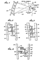
- a SAW bandpass filter includes a phased array of input tranducers, indicated generally by reference numeral 20, and a single interdigital output transducer 22, both input and output transducers being disposed on the surface of a piezoelectric substrate 24.
- An electrical input signal typically having a wide band of frequency components is applied to the input transducer array 20, and the device functions to provide a selected band of output signals from the output transducer 22.
- the principle of operation of the phased input array 20 is analagous to that of an optical diffraction grating.
- the input transducer array includes a relatively large number of individual transducers, each of which, at least in theory, functions as a point source of acoustic energy. If the substrate material is isotropic, the point sources of radiation give rise to circular wavefronts emanating from each input transducer. In practice, many SAW substrates are anisotropic, and the wavefront velocity is dependent on the direction of propagation.
- the transducers in the input array 20 are positioned on a circular arc, and the separate wavefronts from all of the transducers will reinforce each other at a zero-order focal point, indicated at 26, which is equidistant from all of the transducers.
- the zero-order focal point will be the same regardless of the frequency of the signals.
- there is a first-order focal point such as is shown at 28, where the acoustic waves from all of the input tranducers also combine to reinforce each other, but there is a one-wavelength difference in the path lengths to the focal point from any two adjacent transducers.
- the position of this first-order focal point shifts laterally along a focal arc, indicated at 30.
- the output transducer 22 is positioned at a point on the focal arc 30 corresponding to the center frequency of the bandpass filter.
- the device as described may be further improved by the use of amplitude weighting in the input transducer array, as will now be described in more detail with reference to FIGS. 2-6.
- FIG. 2 shows how the input transducer array 20 is amplitude-weighted by varying the width of each transducer.
- the transducer structure illustrated includes two electrodes 34 and 36 arranged in an approximately parallel relationship and having sum bars 38 and 40 extending toward each other in an overlapping relationship, referred to as an interdigital relationship. Extending from each of the sum bars are transducer elements or fingers 42. These are also arranged in an interdigital relationship.
- Each interdigital set of fingers 42 constitutes a transducer cell, and it will be seen that the three cells shown have different apertures or widths, i.e. the transducer fingers overlap by different amounts. This provides a continuously variable control over the transducer cell amplitude, so that the array 20 may be amplitude weighted in any desired manner to minimize sidelobes from the acoustic beam emanating from the array.
- FIG. 3 shows another type of amplitude weighting, employing series capacitance elements.
- two electrodes 46 and 48 are shown as substantially parallel.
- each electrode has sum bars 50 and 52 that are interdigital in form, but the sum bars 50 do not connect directly with the main electrode 46. Instead, they terminate in enlarged pads 54 beneath the electrode 46, and are separated therefrom by a dielectric layer, such as silicon dioxide (Si0 2 ), which is not shown in FIG. 3.
- a dielectric layer such as silicon dioxide (Si0 2 )
- Si0 2 silicon dioxide
- FIG. 4 illustrates a form of resistive weighting for the same general purpose.
- there are two substantially parallel electrodes 56 and 58 each of which has sum bars 60 and 62.
- the sum bars 60 do not overlap the sum bars 62. Instead, they overlap subsidiary sum bars 60a, which are joined to the main sum bars 60 by relatively thin conductive strips 64.
- the subsidiary sum bars 60a overlap the opposing sum bars 62, and there are interdigital fingers 66 extending from both the sum bars 62 and the subsidiary sum bars 60a.
- the conductive strips 64 are used as adjustable resistive elements, and may be trimmed by laser or other methods, for any needed fine-tuning prior to completion of the fabrication process.
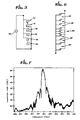
- FIG. 5 shows another technique for amplitude weighting of the input transducer array 20.
- Six transducer cells 70-75 are shown by way of example, connected to an input signal source 76.
- Transducers that are the first two in the array, i.e. those referred to by numerals 70 and 71, are connected in series with the signal source 76.
- the last two transducers 74 and 75 in the array are also connected in series.
- the two transducers 72 and 73 in the middle of the array are connected in parallel directly to the signal source 76. This provides a coarse form of amplitude weighting, since it will be seen that the amplitude resulting from the middle transducers 72 and 73 will be twice that of the outer transducers 70, 71, 74 and 75.
- FIG. 6 Another coarse form of amplitude weighting is shown in FIG. 6. Basically, transducers near the center of the array 20 are closely spaced as usual, as indicated at 80, but are spaced less closely as the ends of the array are approached. Numeral 82 indicates spaces in the array that would normally accommodate one additional transducer, and numeral 84 indicates spaces that would normally accommodate two additional transducers. In practice, these last-described coarse weighting techniques can be best applied in combination with another approach, such as aperture width weighting, for fine-tuning the array to provide a desired output pattern.
- the improved bandpass filter of the invention has good frequency characteristics even when the transducers are not designed to be frequency selective. With appropriate frequency- selective tranducers, the device can achieve up to 90 dB out-of-band rejection.
- the present invention represents a significant advance in the field of surface acoustic wave devices.
- the invention provides improved performance in a SAW bandpass filter.
- the new filter has improved sidelobe rejection and practically eliminates problems due to bulk waves, and other effects such as diffraction, feedthrough and wavefront distortion.
- the preferred embodiment of the invention has been described in detail for purposes of illustration, various modifications may be made without departing from the spirit and scope of the invention. Accordingly, the invention is not to be limited except as by the appended claims.
Landscapes
- Physics & Mathematics (AREA)
- Acoustics & Sound (AREA)
- Surface Acoustic Wave Elements And Circuit Networks Thereof (AREA)
Applications Claiming Priority (2)
| Application Number | Priority Date | Filing Date | Title |
|---|---|---|---|
| US58041884A | 1984-02-15 | 1984-02-15 | |
| US580418 | 1984-02-15 |
Publications (2)
| Publication Number | Publication Date |
|---|---|
| EP0153092A2 true EP0153092A2 (fr) | 1985-08-28 |
| EP0153092A3 EP0153092A3 (fr) | 1987-02-04 |
Family
ID=24321030
Family Applications (1)
| Application Number | Title | Priority Date | Filing Date |
|---|---|---|---|
| EP85300808A Withdrawn EP0153092A3 (fr) | 1984-02-15 | 1985-02-07 | Filtre passe bande à ondes acoustiques de surface |
Country Status (2)
| Country | Link |
|---|---|
| EP (1) | EP0153092A3 (fr) |
| JP (1) | JPS60242716A (fr) |
Cited By (4)
| Publication number | Priority date | Publication date | Assignee | Title |
|---|---|---|---|---|
| US5189330A (en) * | 1989-08-16 | 1993-02-23 | Clarion Co., Ltd. | Surface acoustic wave device |
| US5815055A (en) * | 1995-07-24 | 1998-09-29 | Canon Kabushiki Kaisha | Matched filter with improved synchronous characteristics, and reception device and communication system using the same |
| DE10155570B4 (de) * | 2001-11-13 | 2011-06-22 | Epcos Ag, 81669 | Interdigitalwandler mit verringerter Beugung von Oberflächenwellen |
| DE10159449B4 (de) * | 2001-12-04 | 2012-05-03 | Epcos Ag | Schaltbares Oberflächenwellenfilter |
Family Cites Families (3)
| Publication number | Priority date | Publication date | Assignee | Title |
|---|---|---|---|---|
| DE2431620A1 (de) * | 1974-07-02 | 1976-01-22 | Fraunhofer Ges Forschung | Schallwandler fuer akustische oberflaechenwellen |
| US4114116A (en) * | 1977-08-01 | 1978-09-12 | United Technologies Corporation | Two-dimensional surface acoustic wave signal processor |
| US4321567A (en) * | 1980-03-24 | 1982-03-23 | Raytheon Company | Combining series sections weighting with withdrawal weighting in SAW transducers |
-
1985
- 1985-02-07 EP EP85300808A patent/EP0153092A3/fr not_active Withdrawn
- 1985-02-15 JP JP60028110A patent/JPS60242716A/ja active Pending
Cited By (4)
| Publication number | Priority date | Publication date | Assignee | Title |
|---|---|---|---|---|
| US5189330A (en) * | 1989-08-16 | 1993-02-23 | Clarion Co., Ltd. | Surface acoustic wave device |
| US5815055A (en) * | 1995-07-24 | 1998-09-29 | Canon Kabushiki Kaisha | Matched filter with improved synchronous characteristics, and reception device and communication system using the same |
| DE10155570B4 (de) * | 2001-11-13 | 2011-06-22 | Epcos Ag, 81669 | Interdigitalwandler mit verringerter Beugung von Oberflächenwellen |
| DE10159449B4 (de) * | 2001-12-04 | 2012-05-03 | Epcos Ag | Schaltbares Oberflächenwellenfilter |
Also Published As
| Publication number | Publication date |
|---|---|
| EP0153092A3 (fr) | 1987-02-04 |
| JPS60242716A (ja) | 1985-12-02 |
Similar Documents
| Publication | Publication Date | Title |
|---|---|---|
| EP0309003B1 (fr) | Analyseur de spectre d'ondes de surface acoustiques | |
| EP0161040B1 (fr) | Analyseur spectral employant des ondes superficielles acoustiques | |
| EP0850510B1 (fr) | Dispositif spudt saw conique pondere | |
| CA1180436A (fr) | Resonateur pour ondes acoustiques de surface | |
| US4642506A (en) | Surface acoustic wave device with reflectors in inter-electrode location | |
| US4910839A (en) | Method of making a single phase unidirectional surface acoustic wave transducer | |
| US3970970A (en) | Multiple acoustically coupled surface acoustic wave resonators | |
| US6791236B1 (en) | Method utilizing the saw velocity dispersion effect for weighting by shaping the electrode fingers of a saw interdigital transducer and apparatus produced thereby | |
| US5289073A (en) | Unidirectional surface acoustic wave transducer | |
| US4296348A (en) | Interdigitated electrode ultrasonic transducer | |
| US4827229A (en) | Broad band bulk acoustic wave spectrum analyzer/channelizer | |
| US5818310A (en) | Series-block and line-width weighted saw filter device | |
| EP0153092A2 (fr) | Filtre passe bande à ondes acoustiques de surface | |
| US4947073A (en) | Saw channelized filters | |
| US4365220A (en) | Surface wave circuit device | |
| EP0136114B1 (fr) | Système de traitement de signal | |
| US3968461A (en) | Acoustic surface-wave devices | |
| US4527866A (en) | Acousto-optic transducer | |
| JPH0450564B2 (fr) | ||
| US4393321A (en) | Surface acoustic wave transducer | |
| US4074213A (en) | Elastic bulk wave frequency filter | |
| JP2685537B2 (ja) | 弾性表面波装置、その製作方法、その調整方法、及びそれを用いた通信装置 | |
| US4101852A (en) | Microacoustic shear bulk wave device | |
| US4146852A (en) | Phase weighted acoustic reflective array compressor | |
| US4206426A (en) | Multiple pole surface wave acoustic filters employing angled grooved distributed reflector arrays |
Legal Events
| Date | Code | Title | Description |
|---|---|---|---|
| PUAI | Public reference made under article 153(3) epc to a published international application that has entered the european phase |
Free format text: ORIGINAL CODE: 0009012 |
|
| AK | Designated contracting states |
Designated state(s): DE FR GB IT |
|
| PUAL | Search report despatched |
Free format text: ORIGINAL CODE: 0009013 |
|
| AK | Designated contracting states |
Kind code of ref document: A3 Designated state(s): DE FR GB IT |
|
| STAA | Information on the status of an ep patent application or granted ep patent |
Free format text: STATUS: THE APPLICATION IS DEEMED TO BE WITHDRAWN |
|
| 18D | Application deemed to be withdrawn |
Effective date: 19871006 |
|
| RIN1 | Information on inventor provided before grant (corrected) |
Inventor name: LAU, KEI FUNG Inventor name: KAGIWADA, REYNOLD SHIGERU Inventor name: STOKES, ROBERT BRUCE Inventor name: YEN, KUO-HSIUNG |