EP0153225A2 - Wärmetauscher mit einem Notkühlsystem und schneller Kernreaktor mit einem derartigen Wärmetauscher - Google Patents
Wärmetauscher mit einem Notkühlsystem und schneller Kernreaktor mit einem derartigen Wärmetauscher Download PDFInfo
- Publication number
- EP0153225A2 EP0153225A2 EP85400211A EP85400211A EP0153225A2 EP 0153225 A2 EP0153225 A2 EP 0153225A2 EP 85400211 A EP85400211 A EP 85400211A EP 85400211 A EP85400211 A EP 85400211A EP 0153225 A2 EP0153225 A2 EP 0153225A2
- Authority
- EP
- European Patent Office
- Prior art keywords
- exchanger
- inlet
- outlet
- reactor
- liquid metal
- Prior art date
- Legal status (The legal status is an assumption and is not a legal conclusion. Google has not performed a legal analysis and makes no representation as to the accuracy of the status listed.)
- Granted
Links
Images

Classifications
-
- F—MECHANICAL ENGINEERING; LIGHTING; HEATING; WEAPONS; BLASTING
- F28—HEAT EXCHANGE IN GENERAL
- F28D—HEAT-EXCHANGE APPARATUS, NOT PROVIDED FOR IN ANOTHER SUBCLASS, IN WHICH THE HEAT-EXCHANGE MEDIA DO NOT COME INTO DIRECT CONTACT
- F28D1/00—Heat-exchange apparatus having stationary conduit assemblies for one heat-exchange medium only, the media being in contact with different sides of the conduit wall, in which the other heat-exchange medium is a large body of fluid, e.g. domestic or motor car radiators
- F28D1/02—Heat-exchange apparatus having stationary conduit assemblies for one heat-exchange medium only, the media being in contact with different sides of the conduit wall, in which the other heat-exchange medium is a large body of fluid, e.g. domestic or motor car radiators with heat-exchange conduits immersed in the body of fluid
- F28D1/0206—Heat exchangers immersed in a large body of liquid
- F28D1/0213—Heat exchangers immersed in a large body of liquid for heating or cooling a liquid in a tank
-
- G—PHYSICS
- G21—NUCLEAR PHYSICS; NUCLEAR ENGINEERING
- G21C—NUCLEAR REACTORS
- G21C15/00—Cooling arrangements within the pressure vessel containing the core; Selection of specific coolants
- G21C15/18—Emergency cooling arrangements; Removing shut-down heat
-
- F—MECHANICAL ENGINEERING; LIGHTING; HEATING; WEAPONS; BLASTING
- F28—HEAT EXCHANGE IN GENERAL
- F28D—HEAT-EXCHANGE APPARATUS, NOT PROVIDED FOR IN ANOTHER SUBCLASS, IN WHICH THE HEAT-EXCHANGE MEDIA DO NOT COME INTO DIRECT CONTACT
- F28D21/00—Heat-exchange apparatus not covered by any of the groups F28D1/00 - F28D20/00
- F28D2021/0019—Other heat exchangers for particular applications; Heat exchange systems not otherwise provided for
- F28D2021/0054—Other heat exchangers for particular applications; Heat exchange systems not otherwise provided for for nuclear applications
-
- Y—GENERAL TAGGING OF NEW TECHNOLOGICAL DEVELOPMENTS; GENERAL TAGGING OF CROSS-SECTIONAL TECHNOLOGIES SPANNING OVER SEVERAL SECTIONS OF THE IPC; TECHNICAL SUBJECTS COVERED BY FORMER USPC CROSS-REFERENCE ART COLLECTIONS [XRACs] AND DIGESTS
- Y02—TECHNOLOGIES OR APPLICATIONS FOR MITIGATION OR ADAPTATION AGAINST CLIMATE CHANGE
- Y02E—REDUCTION OF GREENHOUSE GAS [GHG] EMISSIONS, RELATED TO ENERGY GENERATION, TRANSMISSION OR DISTRIBUTION
- Y02E30/00—Energy generation of nuclear origin
- Y02E30/30—Nuclear fission reactors
Definitions
- the present invention relates to a heat exchanger comprising means for emergency cooling of the primary fluid.
- the invention also relates to a fast neutron nuclear reactor incorporating one or more exchangers of this type.
- the reactor core In a fast neutron nuclear reactor, the reactor core is immersed in a liquid metal such as sodium contained in a vessel with a vertical axis closed at its upper part by a horizontal closing slab.
- a liquid metal such as sodium contained in a vessel with a vertical axis closed at its upper part by a horizontal closing slab.
- the heat released by the fission reaction in the reactor core is absorbed by the liquid metal contained in the tank.
- This heat is then transmitted by heat exchangers to a secondary fluid generally consisting of liquid sodium.
- the circulation of the primary liquid metal contained in the reactor vessel between the core and the exchangers is controlled by pumps.
- the entire primary circuit, including pumps and exchangers, is located inside the reactor vessel.
- part of the primary circuit comprising the exchangers and sometimes also the pumps is located outside the reactor vessel.
- cooling loops of the reactor For this purpose, it is customary to equip fast neutron nuclear reactors with cooling loops of the reactor when it is stopped. As illustrated in particular by French patent application No. 78 06435 in the name of the French Atomic Energy Commission, these cooling loops generally include heat exchangers immersing directly in the liquid metal contained in the tank and pumps ensuring circulation liquid metal (usually sodium) flowing through these loops. The residual power of the core is thus removed by liquid metal / air exchangers.
- the subject of the present invention is precisely a heat exchanger incorporating emergency cooling means making it possible to replace the emergency cooling exchangers usually used in fast neutron reactors.
- the elimination of the latter makes it possible to avoid all the drawbacks resulting from their presence in the reactor vessel.
- the emergency cooling means incorporated in the exchanger according to the invention are designed so as to be able to operate in natural convection.
- the invention is particularly suitable for use in a fast type neutron reactor of the integrated type, it is not limited to this application and can be used in all cases where it is necessary to add to a conventional heat exchanger an emergency cooling system.
- the invention is particularly suitable for the case of fast-type integrated neutron nuclear reactors, it can also be used in fast-loop type neutron reactors.
- the present invention specifically relates to a heat exchanger comprising a cylindrical casing with a vertical axis, in which is housed a bundle of vertical tubes, the ends of which are fixed respectively to a lower tube plate and to an upper tube plate and open out. respectively in an inlet chamber and in a secondary fluid outlet chamber, an inlet manifold and a second fluid outlet manifold re communicating respectively with the inlet chamber and with the outlet chamber, and an inlet orifice and an outlet orifice for primary fluid formed in the part of the envelope surrounding the bundle of tubes, the exchanger being characterized in what it further comprises means for emergency cooling of the primary fluid comprising an inlet pipe and an outlet pipe suitable for being connected to external cooling means and opening respectively into the inlet chamber and into the chamber secondary fluid outlet, below said pipes.
- the inlet piping is connected to a distribution ramp housed under the lower tube plate and the outlet piping is connected to a manifold located above the plate upper tubes.
- the invention also relates to a fast neutron nuclear reactor comprising a tank filled with liquid metal and closed at its upper end by a slab, at least one pump ensuring the circulation of the liquid metal between the reactor core and at least one exchanger of heat suspended from the slab, this reactor being characterized in that the heat exchanger comprises a device for discharging residual power integrated in accordance with the invention, the primary fluid circulating in the exchanger being the liquid metal contained in the tank and the reactor further comprising external cooling means such as a liquid metal / air exchanger connected between the inlet and outlet pipes of the exchanger.
- the means for cooling the shutdown reactor may operating in natural convection
- pumping means can also be interposed between the exchanger and the external cooling means.
- FIG. 1 shows schematically an integrated type fast neutron nuclear reactor.
- the core 10 of the reactor is immersed in a liquid cooling metal 12 (usually sodium) contained inside a tank 14 with a vertical axis.
- the upper part of the tank 14 is closed by a horizontal closing slab 16 resting on its periphery on a tank well 18.
- the tank 14, called the main tank, is lined inside the tank well 18 by a tank security 20 which is generally suspended from the slab 16, like the tank 14.
- the slab 16 is crossed by a series of components necessary for the operation of the reactor.
- the slab supports in particular in its central part a system of revolving plugs 22 and, in its peripheral part, heat exchangers 24 and primary pumps 26 regularly distributed around the core, and of which only one component of each type is shown in the figure.
- An internal tank 28 defines inside the tank 14 a hot collector 30 containing the hot liquid metal opening at the upper end of the core 10 and a cold collector 32 in which is collected the liquid metal leaving the exchangers 24.
- the metal liquid is then taken up by the pumps 26 to be discharged through lines 34 into a bed base 36 ensuring both the supply of the core 10 with liquid metal and the support of the core on the bottom of the tank 14, by the intermediate of a deck 38.
- the liquid metal thus continuously circulates through the core and the exchangers. These ensure the extraction of the heat given off by the fission reaction. This heat is then transferred to a secondary circuit (not shown) before being exploited in the turbines of a water / steam circuit, to produce electricity.
- a system 40 for cooling the reactor when stopped is introduced inside each of the heat exchangers 13. This system is intended, as already mentioned above, to ensure the evacuation of the residual calorific power that continues to release the reactor core in the event of the primary pumps 26 stopping, despite the fall of the safety bars.
- each of the exchangers 24 of the reactor of FIG. 1 comprises an external cylindrical casing 42, of vertical axis.
- the envelope 42 crosses in a known manner a passage 43 formed in the slab 16 and rests on the upper face thereof by a flange 44.
- the space left free between the passage 43 and the casing 42 to allow the exchanger to be dismantled is filled by an insulation system thermal diagram shown in 45.
- the part of the exchanger 24 situated below the slab 16 constitutes the exchanger proper, while the part of the exchanger situated above the slab constitutes the head of the exchanger, by which the latter is connected to the other components of the corresponding secondary loop.
- the exchanger proper which is immersed in the primary liquid metal 12, comprises a bundle of vertical straight tubes 46 housed in the casing 42.
- the ends of the tubes 46 are fixed in a known manner respectively to a lower horizontal tube plate 48 and to an upper horizontal tube plate 50.
- These two plates 48 and 50 are themselves fixed by their external periphery to the envelope 42 and by their internal periphery to a tube 52, of vertical axis coincident with that of the envelope 42 and which extends from the lower tube plate 48 to above the slab 16.
- Inlet 72 and outlet 74 openings of the primary liquid metal 12 are formed in the casing 42 respectively below the upper tube plate 50 and above the lower tube plate 48. These openings allow the metal liquid 12 to flow from top to bottom around the tubes 46 in the annular space formed between the envelope 42 and the tube 52.
- the tubes 46 open into an inlet chamber 54 for the secondary fluid.
- This room 54 is delimited teeed at its lower end by the bottom of the casing 42. It extends upwards inside a vertical chimney 56 arranged coaxially in the tube 52.
- the chimney 56 is bent at right angles to connect to an inlet pipe 58 of the secondary fluid.
- This tubing 58 passes through the casing 42 of the exchanger.
- the tubes 46 open above the upper tube plate 50 into an annular outlet chamber 60.
- This chamber 60 extends upwards to above the slab 16 in the form of a space annular formed between the tube 52 and an internal envelope 62.
- the envelope 62 is arranged coaxially between the tube 52 and the external envelope 42 and its frustoconical lower end is fixed to the latter above the upper tube plate 50.
- the casing 62 terminates below the inlet pipe 58 in the form of a flat upper face connected by deformable sealing bellows 64 and 66 respectively to the upper end of the tube 52 and to the chimney 56 .
- the upper end of the manifold 60 opens into an outlet pipe 68 passing tightly through the casing 42 of the exchanger.
- a mixer 71 can be fixed to the tube 52, inside the outlet manifold 60, just above the tube plate 50.
- the secondary liquid metal (usually sodium) introduced by the tubing 58 descends into the exchanger through the chimney 56 of the inlet chamber 54. It then rises in the bundle of tubes 46 to accumulate the heat which is transmitted to it by the primary liquid metal 12 circulating around the tubes. It finally rises in the outlet chamber 60 to exit the exchanger through the pipe 68.
- the secondary liquid metal usually sodium
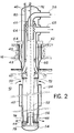
- the exchanger shown in FIG. 2 further comprises means 40 for emergency cooling of the primary liquid metal 12 which circulates around the tubes 46.
- These emergency cooling means 40 comprise a first vertical tube 76 disposed along the axis of the exchanger.
- the tube 76 successively crosses the upper dome of the envelope 42 and the bent part of the chimney 56 to descend inside the latter to the part of the inlet chamber 54 located below the plate with lower tubes 48.
- the vertical tube 76 is connected to a distribution ramp 78 located below the lower tube plate 48.
- the ramp 78 is pierced with orifices on its upper face opposite the plate with tubes 48.
- the emergency cooling means 40 further comprise a vertical outlet pipe 80 offset relative to the axis of the exchanger and successively passing through the upper dome of the casing 42 and the planar upper face of the casing 62.
- L the lower end of the outlet pipe 80 is situated approximately at the level of the lower face of the slab 16.
- the pipe 80 is connected at this level to an annular manifold 82 whose lower part is pierced with orifices around the entire periphery of the outlet chamber 60.
- the inlet 76 and outlet 80 pipes both open out- below the level of the outlet pipe 68 of the secondary loop, the latter itself being located below the inlet pipe 58.
- the secondary part of the exchanger 24 in which the pipes 76 and 80 are immersed remains immersed in the secondary liquid metal, even when the corresponding secondary loop is drained.
- the cooling loop 84 of the shutdown reactor comprises, outside the exchanger 24, a liquid metal / air exchanger of known type, which is shown schematically at 86.
- This loop 84 may further include a circulation pump, for example electromagnetic.
- the circulation of the secondary liquid metal inside the loop 84 is ensured automatically by natural convection, so that such a pump is not essential to the invention.
- the characteristics of the invention it can be seen that in the event of the primary pumps stopping and the safety bars falling into the reactor core, the residual power which the reactor core continues to generate is evacuated by a circulation in natural convection or, possibly, forced by means of a pump, of the secondary liquid metal contained in the exchanger. In fact, as indicated by the arrows in FIG. 2, this liquid metal then flows from bottom to top between the distribution ramp 78 and the collecting ramp 82 inside the tubes 46 of the exchanger to extract the heat conveyed by the primary liquid metal, which itself circulates around the tubes between the inlet 72 and outlet 74 ports.
- the heated liquid metal taken off by the manifold 82 is conveyed by the outlet piping 80 and by the external loop 84 to the interchange liquid metal / air 86 where it is again cooled.
- the liquid metal then returns via the inlet piping 76 to the distribution ramp 78, to start a new cycle.
- the cooling system of the stopped reactor thus produced can be used even in the event of unavailability of the secondary circuits of the reactor.
- the description which has just been made shows that this system is particularly simple.
- it has great reliability if all the exchangers 24 are equipped with it.
- it also has the advantage of being able to operate in natural convection, which constitutes an important advantage from the point of view of safety.
- the invention is not limited to the embodiment which has just been described by way of example, but covers all its variants.
- the invention is not limited to a heat exchanger intended to be used between the primary and secondary circuits of an integrated type fast neutron nuclear reactor. Indeed, it is easily understood that such a system could also be used in an exchanger placed between the primary and secondary circuits of a fast loop type neutron reactor. More generally, an exchanger according to the invention could also be used in any other application requiring emergency cooling means of the primary fluid having a reduced capacity compared to the heat exchange capacity presented by the exchanger in operation normal.
- the exchanger according to the invention can optionally They should also be combined with exchangers of conventional design.
- the invention can be applied to all exchangers in which the inlet and outlet pipes for the secondary fluid are located at the upper part of the casing of the 'exchanger. Indeed, it is then always possible to clear the inlet and outlet pipes of the emergency cooling means below these pipes in order to ensure the operation of the emergency cooling system, even in the event of draining of the secondary circuit. Similarly, the distribution ramp and the manifold could be modified or even deleted without departing from the scope of the invention.
Landscapes
- Engineering & Computer Science (AREA)
- Physics & Mathematics (AREA)
- General Engineering & Computer Science (AREA)
- Plasma & Fusion (AREA)
- High Energy & Nuclear Physics (AREA)
- Thermal Sciences (AREA)
- Mechanical Engineering (AREA)
- Heat-Exchange Devices With Radiators And Conduit Assemblies (AREA)
- Structure Of Emergency Protection For Nuclear Reactors (AREA)
Applications Claiming Priority (2)
| Application Number | Priority Date | Filing Date | Title |
|---|---|---|---|
| FR8402214A FR2561367B1 (fr) | 1984-02-14 | 1984-02-14 | Echangeur de chaleur equipe de moyens de refroidissement de secours et reacteur nucleaire a neutrons rapides comportant un tel echangeur |
| FR8402214 | 1984-02-14 |
Publications (3)
| Publication Number | Publication Date |
|---|---|
| EP0153225A2 true EP0153225A2 (de) | 1985-08-28 |
| EP0153225A3 EP0153225A3 (en) | 1985-09-25 |
| EP0153225B1 EP0153225B1 (de) | 1988-02-03 |
Family
ID=9301026
Family Applications (1)
| Application Number | Title | Priority Date | Filing Date |
|---|---|---|---|
| EP85400211A Expired EP0153225B1 (de) | 1984-02-14 | 1985-02-08 | Wärmetauscher mit einem Notkühlsystem und schneller Kernreaktor mit einem derartigen Wärmetauscher |
Country Status (5)
| Country | Link |
|---|---|
| US (1) | US4698201A (de) |
| EP (1) | EP0153225B1 (de) |
| JP (1) | JPS60188888A (de) |
| DE (1) | DE3561568D1 (de) |
| FR (1) | FR2561367B1 (de) |
Cited By (4)
| Publication number | Priority date | Publication date | Assignee | Title |
|---|---|---|---|---|
| GB2189339A (en) * | 1986-04-21 | 1987-10-21 | Ansaldo Spa | Reactor block of a fast reactor for evacuation by natural circulation of the residual power of the core |
| EP0541297A1 (de) * | 1991-11-08 | 1993-05-12 | Westinghouse Electric Corporation | Wärmetauscher |
| FR2693309A1 (fr) * | 1992-07-01 | 1994-01-07 | Framatome Sa | Procédé et dispositif d'évacuation de la puissance résiduelle d'un réacteur nucléaire à neurton rapides à l'arrêt. |
| WO2008125963A3 (en) * | 2007-04-16 | 2008-12-11 | Del Nova Vis S R L | System for evacuating the residual heat from a liquid metal or molten salts cooled nuclear reactor |
Families Citing this family (6)
| Publication number | Priority date | Publication date | Assignee | Title |
|---|---|---|---|---|
| JPH0593794A (ja) * | 1991-10-01 | 1993-04-16 | Toshiba Corp | ナトリウム冷却型高速炉 |
| US6763645B2 (en) * | 2003-05-14 | 2004-07-20 | Stanley F. Hunter | Protecting building frames from fire and heat to avoid catastrophic failure |
| FR2997542A1 (fr) * | 2012-10-26 | 2014-05-02 | Commissariat Energie Atomique | Dispositif d'evacuation de la puissance residuelle d'un reacteur nucleaire a neutrons rapides, integre a un echangeur de chaleur intermediaire, et reacteur comportant ce dispositif |
| CN103366838B (zh) * | 2013-07-17 | 2015-08-12 | 中国科学院上海应用物理研究所 | 一种熔盐堆缓冲盐自然循环冷却系统 |
| RU2554082C2 (ru) * | 2013-07-18 | 2015-06-27 | Георгий Эрикович Лазаренко | Канал аварийного расхолаживания ядерного реактора |
| RU2670428C1 (ru) * | 2017-08-07 | 2018-10-23 | Общество с ограниченной ответственностью "Научно-технический центр инноваций" | Система и способ аварийного расхолаживания ядерного реактора |
Family Cites Families (6)
| Publication number | Priority date | Publication date | Assignee | Title |
|---|---|---|---|---|
| US2800307A (en) * | 1954-06-04 | 1957-07-23 | Stratford Eng Corp | Apparatus for controlling temperature change of blends of fluids or fluids and finely divided solids |
| FR2335916A1 (fr) * | 1975-12-18 | 1977-07-15 | Stein Industrie | Dispositif auxiliaire de refroidissement pour echangeur de chaleur a fluide primaire rechauffe dans un reacteur nucleaire |
| US4235284A (en) * | 1976-12-16 | 1980-11-25 | The United States Of America As Represented By The United States Department Of Energy | Heat exchanger with auxiliary cooling system |
| FR2419565A1 (fr) * | 1978-03-07 | 1979-10-05 | Commissariat Energie Atomique | Echangeur d'ultime secours, notamment pour reacteur nucleaire a neutrons rapides |
| FR2466841A1 (fr) * | 1979-09-28 | 1981-04-10 | Commissariat Energie Atomique | Reacteur nucleaire dont les generateurs de vapeur sont equipes d'une capacite reserve |
| FR2506498B1 (fr) * | 1981-05-22 | 1986-03-07 | Commissariat Energie Atomique | Reacteur nucleaire a neutrons rapides muni de dispositifs d'evacuation de la puissance residuelle |
-
1984
- 1984-02-14 FR FR8402214A patent/FR2561367B1/fr not_active Expired
-
1985
- 1985-01-31 US US06/696,732 patent/US4698201A/en not_active Expired - Fee Related
- 1985-02-08 DE DE8585400211T patent/DE3561568D1/de not_active Expired
- 1985-02-08 EP EP85400211A patent/EP0153225B1/de not_active Expired
- 1985-02-14 JP JP60025323A patent/JPS60188888A/ja active Granted
Cited By (6)
| Publication number | Priority date | Publication date | Assignee | Title |
|---|---|---|---|---|
| GB2189339A (en) * | 1986-04-21 | 1987-10-21 | Ansaldo Spa | Reactor block of a fast reactor for evacuation by natural circulation of the residual power of the core |
| GB2189339B (en) * | 1986-04-21 | 1989-11-29 | Ansaldo Spa | Nuclear reactor. |
| EP0541297A1 (de) * | 1991-11-08 | 1993-05-12 | Westinghouse Electric Corporation | Wärmetauscher |
| FR2693309A1 (fr) * | 1992-07-01 | 1994-01-07 | Framatome Sa | Procédé et dispositif d'évacuation de la puissance résiduelle d'un réacteur nucléaire à neurton rapides à l'arrêt. |
| US5392324A (en) * | 1992-07-01 | 1995-02-21 | Framatome | Device for and method of removing the residual power from a fast-neutron nuclear reactor at shutdown |
| WO2008125963A3 (en) * | 2007-04-16 | 2008-12-11 | Del Nova Vis S R L | System for evacuating the residual heat from a liquid metal or molten salts cooled nuclear reactor |
Also Published As
| Publication number | Publication date |
|---|---|
| EP0153225B1 (de) | 1988-02-03 |
| US4698201A (en) | 1987-10-06 |
| DE3561568D1 (en) | 1988-03-10 |
| FR2561367B1 (fr) | 1986-08-29 |
| FR2561367A1 (fr) | 1985-09-20 |
| JPH0531750B2 (de) | 1993-05-13 |
| JPS60188888A (ja) | 1985-09-26 |
| EP0153225A3 (en) | 1985-09-25 |
Similar Documents
| Publication | Publication Date | Title |
|---|---|---|
| EP0004218B1 (de) | Schneller Kernreaktor mit mindestens einem Hilfs-Wärmetauscher | |
| EP0153225B1 (de) | Wärmetauscher mit einem Notkühlsystem und schneller Kernreaktor mit einem derartigen Wärmetauscher | |
| EP0246969B1 (de) | Kleiner Druckwasserkernreaktor mit Naturumlauf | |
| WO2013107817A1 (fr) | Système d'évacuation de la puissance résiduelle d'un réacteur nucléaire à eau sous pression | |
| FR2462002A1 (fr) | Reacteur nucleaire refroidi par un metal liquide et muni d'un systeme d'evacuation de la puissance residuelle | |
| FR2763168A1 (fr) | Reacteur nucleaire a eau, dont la cuve contient un dispositif de recuperation du coeur apres sa fusion accidentelle | |
| FR2620559A1 (fr) | Reacteur nucleaire a metal liquide supporte par le fond | |
| EP0068913B1 (de) | Schneller Brüter mit Einrichtung zur Abführung von Restwärme | |
| EP0006802A1 (de) | Mit flüssigem Metall gekühlter schneller Kernreaktor | |
| FR2506063A1 (fr) | Reacteur nucleaire comportant un refroidissement des structures peripheriques par convection naturelle d'air | |
| EP0083545B1 (de) | Sicherheitsvorrichtung zur Ableitung der entstehenden Wärme beim Abschalten eines schnellen Brüters | |
| EP0018262B1 (de) | Schneller Kernreaktor mit einem zylindrischen Innenbehälter | |
| EP0163564A1 (de) | Schneller Neutronenkernreaktor mit Dampferzeuger, integriert im Behälter | |
| EP0055963B1 (de) | Flüssigmetallgekühlter Kernreaktor mit einem am Boden gekühlten Behälter | |
| EP0067103B1 (de) | Schneller Brutreaktor | |
| EP0048672B1 (de) | Atomkernreaktor mit Wärmetauschern in integrierter Bauweise | |
| EP0258131B1 (de) | Notkühleinrichtung für schnellen Neutronenreaktor | |
| EP3945531B1 (de) | Reaktor und sicherheitsverfahren für reaktor im falle einer kernschmelze | |
| EP0156689B1 (de) | Schneller Kernreaktor mit hängendem Hauptbecken und Deckel | |
| FR2555794A1 (fr) | Reacteur nucleaire a neutrons rapides equipe de moyens de refroidissement de secours | |
| EP0206921B1 (de) | Wärmetauscher mit koaxialen U-Rohren und Zwischenkreislauf von neutralem Gas und schneller Neutronenreaktor mit solchem Wärmetauscher | |
| EP4639582A1 (de) | Modular aufgebauter druckwasserkernreaktor (prpr) mit druckhalter ohne wasserbesprühung | |
| EP0161949B1 (de) | Mit flüssigem Metall gekühlter Kernreaktor | |
| WO2024133281A1 (fr) | Installation nucléaire comprenant au moins un réacteur nucléaire modulaire (smr) et un puits de cuve délimitant un bassin d'eau dans lequel le bloc réacteur smr est immergé | |
| FR2561811A1 (fr) | Reacteur surregenerateur rapide a refroidissement par metal liquide |
Legal Events
| Date | Code | Title | Description |
|---|---|---|---|
| PUAI | Public reference made under article 153(3) epc to a published international application that has entered the european phase |
Free format text: ORIGINAL CODE: 0009012 |
|
| PUAL | Search report despatched |
Free format text: ORIGINAL CODE: 0009013 |
|
| AK | Designated contracting states |
Designated state(s): BE DE GB IT NL |
|
| AK | Designated contracting states |
Designated state(s): BE DE GB IT NL |
|
| 17P | Request for examination filed |
Effective date: 19860227 |
|
| 17Q | First examination report despatched |
Effective date: 19870414 |
|
| GRAA | (expected) grant |
Free format text: ORIGINAL CODE: 0009210 |
|
| RAP1 | Party data changed (applicant data changed or rights of an application transferred) |
Owner name: ELECTRICITE DE FRANCE SERVICE NATIONAL Owner name: COMMISSARIAT A L'ENERGIE ATOMIQUE |
|
| AK | Designated contracting states |
Kind code of ref document: B1 Designated state(s): BE DE GB IT NL |
|
| REF | Corresponds to: |
Ref document number: 3561568 Country of ref document: DE Date of ref document: 19880310 |
|
| ITF | It: translation for a ep patent filed | ||
| GBT | Gb: translation of ep patent filed (gb section 77(6)(a)/1977) | ||
| PLBE | No opposition filed within time limit |
Free format text: ORIGINAL CODE: 0009261 |
|
| STAA | Information on the status of an ep patent application or granted ep patent |
Free format text: STATUS: NO OPPOSITION FILED WITHIN TIME LIMIT |
|
| 26N | No opposition filed | ||
| PGFP | Annual fee paid to national office [announced via postgrant information from national office to epo] |
Ref country code: BE Payment date: 19900131 Year of fee payment: 6 |
|
| ITTA | It: last paid annual fee | ||
| PGFP | Annual fee paid to national office [announced via postgrant information from national office to epo] |
Ref country code: NL Payment date: 19900228 Year of fee payment: 6 |
|
| PG25 | Lapsed in a contracting state [announced via postgrant information from national office to epo] |
Ref country code: BE Effective date: 19910228 |
|
| PG25 | Lapsed in a contracting state [announced via postgrant information from national office to epo] |
Ref country code: NL Effective date: 19910901 |
|
| NLV4 | Nl: lapsed or anulled due to non-payment of the annual fee | ||
| PGFP | Annual fee paid to national office [announced via postgrant information from national office to epo] |
Ref country code: GB Payment date: 19930202 Year of fee payment: 9 |
|
| PGFP | Annual fee paid to national office [announced via postgrant information from national office to epo] |
Ref country code: DE Payment date: 19930203 Year of fee payment: 9 |
|
| PG25 | Lapsed in a contracting state [announced via postgrant information from national office to epo] |
Ref country code: GB Effective date: 19940208 |
|
| GBPC | Gb: european patent ceased through non-payment of renewal fee |
Effective date: 19940208 |
|
| PG25 | Lapsed in a contracting state [announced via postgrant information from national office to epo] |
Ref country code: DE Effective date: 19941101 |