EP0163564A1 - Schneller Neutronenkernreaktor mit Dampferzeuger, integriert im Behälter - Google Patents
Schneller Neutronenkernreaktor mit Dampferzeuger, integriert im Behälter Download PDFInfo
- Publication number
- EP0163564A1 EP0163564A1 EP85400878A EP85400878A EP0163564A1 EP 0163564 A1 EP0163564 A1 EP 0163564A1 EP 85400878 A EP85400878 A EP 85400878A EP 85400878 A EP85400878 A EP 85400878A EP 0163564 A1 EP0163564 A1 EP 0163564A1
- Authority
- EP
- European Patent Office
- Prior art keywords
- tubes
- reactor
- steam
- water
- liquid metal
- Prior art date
- Legal status (The legal status is an assumption and is not a legal conclusion. Google has not performed a legal analysis and makes no representation as to the accuracy of the status listed.)
- Granted
Links
- XLYOFNOQVPJJNP-UHFFFAOYSA-N water Substances O XLYOFNOQVPJJNP-UHFFFAOYSA-N 0.000 claims abstract description 72
- 229910001338 liquidmetal Inorganic materials 0.000 claims abstract description 37
- 230000007935 neutral effect Effects 0.000 claims abstract description 37
- 230000004087 circulation Effects 0.000 claims description 13
- 239000012530 fluid Substances 0.000 claims description 7
- 238000001816 cooling Methods 0.000 claims description 4
- 230000000295 complement effect Effects 0.000 claims description 2
- 230000003068 static effect Effects 0.000 claims 1
- 239000001307 helium Substances 0.000 abstract description 37
- 229910052734 helium Inorganic materials 0.000 abstract description 37
- SWQJXJOGLNCZEY-UHFFFAOYSA-N helium atom Chemical compound [He] SWQJXJOGLNCZEY-UHFFFAOYSA-N 0.000 abstract description 37
- 239000007789 gas Substances 0.000 abstract description 28
- DGAQECJNVWCQMB-PUAWFVPOSA-M Ilexoside XXIX Chemical compound C[C@@H]1CC[C@@]2(CC[C@@]3(C(=CC[C@H]4[C@]3(CC[C@@H]5[C@@]4(CC[C@@H](C5(C)C)OS(=O)(=O)[O-])C)C)[C@@H]2[C@]1(C)O)C)C(=O)O[C@H]6[C@@H]([C@H]([C@@H]([C@H](O6)CO)O)O)O.[Na+] DGAQECJNVWCQMB-PUAWFVPOSA-M 0.000 description 32
- 239000011734 sodium Substances 0.000 description 32
- 229910052708 sodium Inorganic materials 0.000 description 32
- KEAYESYHFKHZAL-BJUDXGSMSA-N sodium-22 Chemical compound [22Na] KEAYESYHFKHZAL-BJUDXGSMSA-N 0.000 description 5
- XKRFYHLGVUSROY-UHFFFAOYSA-N Argon Chemical compound [Ar] XKRFYHLGVUSROY-UHFFFAOYSA-N 0.000 description 4
- 239000007788 liquid Substances 0.000 description 4
- 238000004519 manufacturing process Methods 0.000 description 4
- 238000005192 partition Methods 0.000 description 4
- 238000006243 chemical reaction Methods 0.000 description 3
- 230000002349 favourable effect Effects 0.000 description 3
- 238000010438 heat treatment Methods 0.000 description 3
- 238000009413 insulation Methods 0.000 description 3
- 229910052751 metal Inorganic materials 0.000 description 3
- 239000002184 metal Substances 0.000 description 3
- 230000003071 parasitic effect Effects 0.000 description 3
- 230000000630 rising effect Effects 0.000 description 3
- CURLTUGMZLYLDI-UHFFFAOYSA-N Carbon dioxide Chemical compound O=C=O CURLTUGMZLYLDI-UHFFFAOYSA-N 0.000 description 2
- 229910052786 argon Inorganic materials 0.000 description 2
- 230000008901 benefit Effects 0.000 description 2
- 238000007689 inspection Methods 0.000 description 2
- 230000010354 integration Effects 0.000 description 2
- 230000008439 repair process Effects 0.000 description 2
- 241000233805 Phoenix Species 0.000 description 1
- 229910000831 Steel Inorganic materials 0.000 description 1
- 241000274584 Virola Species 0.000 description 1
- 229910002092 carbon dioxide Inorganic materials 0.000 description 1
- 239000001569 carbon dioxide Substances 0.000 description 1
- 230000008859 change Effects 0.000 description 1
- 238000001514 detection method Methods 0.000 description 1
- 238000001035 drying Methods 0.000 description 1
- 230000005611 electricity Effects 0.000 description 1
- 230000008030 elimination Effects 0.000 description 1
- 238000003379 elimination reaction Methods 0.000 description 1
- 238000000605 extraction Methods 0.000 description 1
- 230000004992 fission Effects 0.000 description 1
- 238000002513 implantation Methods 0.000 description 1
- 238000009434 installation Methods 0.000 description 1
- 238000000034 method Methods 0.000 description 1
- 239000000203 mixture Substances 0.000 description 1
- 238000012544 monitoring process Methods 0.000 description 1
- 230000002093 peripheral effect Effects 0.000 description 1
- 230000005855 radiation Effects 0.000 description 1
- 230000002285 radioactive effect Effects 0.000 description 1
- 230000001869 rapid Effects 0.000 description 1
- 230000009467 reduction Effects 0.000 description 1
- 230000000284 resting effect Effects 0.000 description 1
- 238000007789 sealing Methods 0.000 description 1
- 230000035939 shock Effects 0.000 description 1
- NASFKTWZWDYFER-UHFFFAOYSA-N sodium;hydrate Chemical compound O.[Na] NASFKTWZWDYFER-UHFFFAOYSA-N 0.000 description 1
- 239000010959 steel Substances 0.000 description 1
- 239000008400 supply water Substances 0.000 description 1
- 239000000725 suspension Substances 0.000 description 1
- 230000001131 transforming effect Effects 0.000 description 1
Images



Classifications
-
- G—PHYSICS
- G21—NUCLEAR PHYSICS; NUCLEAR ENGINEERING
- G21C—NUCLEAR REACTORS
- G21C1/00—Reactor types
- G21C1/02—Fast fission reactors, i.e. reactors not using a moderator ; Metal cooled reactors; Fast breeders
- G21C1/03—Fast fission reactors, i.e. reactors not using a moderator ; Metal cooled reactors; Fast breeders cooled by a coolant not essentially pressurised, e.g. pool-type reactors
-
- F—MECHANICAL ENGINEERING; LIGHTING; HEATING; WEAPONS; BLASTING
- F01—MACHINES OR ENGINES IN GENERAL; ENGINE PLANTS IN GENERAL; STEAM ENGINES
- F01K—STEAM ENGINE PLANTS; STEAM ACCUMULATORS; ENGINE PLANTS NOT OTHERWISE PROVIDED FOR; ENGINES USING SPECIAL WORKING FLUIDS OR CYCLES
- F01K3/00—Plants characterised by the use of steam or heat accumulators, or intermediate steam heaters, therein
- F01K3/18—Plants characterised by the use of steam or heat accumulators, or intermediate steam heaters, therein having heaters
- F01K3/181—Plants characterised by the use of steam or heat accumulators, or intermediate steam heaters, therein having heaters using nuclear heat
-
- F—MECHANICAL ENGINEERING; LIGHTING; HEATING; WEAPONS; BLASTING
- F22—STEAM GENERATION
- F22B—METHODS OF STEAM GENERATION; STEAM BOILERS
- F22B1/00—Methods of steam generation characterised by form of heating method
- F22B1/02—Methods of steam generation characterised by form of heating method by exploitation of the heat content of hot heat carriers
- F22B1/06—Methods of steam generation characterised by form of heating method by exploitation of the heat content of hot heat carriers the heat carrier being molten; Use of molten metal, e.g. zinc, as heat transfer medium
- F22B1/063—Methods of steam generation characterised by form of heating method by exploitation of the heat content of hot heat carriers the heat carrier being molten; Use of molten metal, e.g. zinc, as heat transfer medium for metal cooled nuclear reactors
- F22B1/066—Methods of steam generation characterised by form of heating method by exploitation of the heat content of hot heat carriers the heat carrier being molten; Use of molten metal, e.g. zinc, as heat transfer medium for metal cooled nuclear reactors with double-wall tubes having a third fluid between these walls, e.g. helium for leak detection
-
- Y—GENERAL TAGGING OF NEW TECHNOLOGICAL DEVELOPMENTS; GENERAL TAGGING OF CROSS-SECTIONAL TECHNOLOGIES SPANNING OVER SEVERAL SECTIONS OF THE IPC; TECHNICAL SUBJECTS COVERED BY FORMER USPC CROSS-REFERENCE ART COLLECTIONS [XRACs] AND DIGESTS
- Y02—TECHNOLOGIES OR APPLICATIONS FOR MITIGATION OR ADAPTATION AGAINST CLIMATE CHANGE
- Y02E—REDUCTION OF GREENHOUSE GAS [GHG] EMISSIONS, RELATED TO ENERGY GENERATION, TRANSMISSION OR DISTRIBUTION
- Y02E30/00—Energy generation of nuclear origin
- Y02E30/30—Nuclear fission reactors
Definitions
- the present invention relates to a fast neutron nuclear reactor of the type comprising a primary circuit integrated into a tank filled with liquid metal and containing the reactor core as well as primary pumps for circulating this liquid metal, and means for transferring the heat conveyed by the liquid metal to the water circulating in a water / vapor circuit comprising means for transforming this heat into electricity.
- the heat conveyed by the Liquid metal of the primary circuit (generally sodium) is transferred to the water of the water / vapor circuit by an intermediate circuit, said secondary circuit.
- a liquid metal (generally sodium) circulating in the secondary circuit takes the heat conveyed by the primary liquid metal in heat exchangers integrated in the reactor vessel, to transfer it to the water of the water / steam circuit by generators. Steam external to the tank.
- the existing integrated fast neutron reactors therefore comprise an intermediate circuit of liquid metal. This obviously has the consequence of increasing the cost significantly.
- the invention specifically relates to a fast neutron nuclear reactor preserving the integration of the primary circuit inside the reactor vessel while allowing the elimination of the traditional intermediate circuit of liquid metal through the use of steam generators. of a new type which can be placed inside the reactor vessel without a sodium / water reaction being able to take place at this level.
- iL is propped according to the invention a fast neutron nuclear reactor of the type comprising a primary circuit integrated in a tank filled with liquid metal and containing the reactor core as well as means for circulating this liquid metal and Ways to Transfer Heat conveyed by the Liquid metal to the water circulating in a water / steam circuit, characterized in that said heat transfer means comprise at least one steam generator housed in the reactor vessel and comprising at least one bundle of internal tubes in The water in the water / vapor circuit circulates, at least one bundle of external tubes immersed in the primary liquid metal, The external tubes surrounding each of the internal tubes to define with them an annular space under neutral gas pressure, connected to a secondary circuit of low thermal power comprising means for circulating this neutral gas under pressure such as helium in said annular space and ensuring heat exchange.
- said heat transfer means comprise at least one steam generator housed in the reactor vessel and comprising at least one bundle of internal tubes in The water in the water / vapor circuit circulates, at least one bundle of external tubes immersed in the primary liquid metal
- Liquid-gas-neutral metal heat exchangers are actually integrated inside the reactor vessel rather than steam generators in the usual sense of the term.
- the safety requirements are thus preserved and the investment cost of such a reactor is reduced substantially.
- the reactor vessel is closed off by a horizontal closing slab which the vapor generator passes through in a leaktight manner, the latter comprising an upper tube plate above the beam supporting the beam. of internal tubes, open at their lower end, an intermediate tube plate surmounted by a vapor outlet chamber of the water / steam circuit and supporting a bundle of intermediate tubes surrounding the internal tubes, closed at their lower ends and in the bottom from which the internal tubes open, and a lower tube plate surmounted by a neutral gas outlet chamber and supporting the bundle of external tubes in rotating the intermediate tubes, the steam generator further comprising neutral gas tubes connecting the bottom of the external tubes to neutral gas inlet orifices located between the lower tube plate and the closing slab.
- each of the neutral gas tubes preferably comprises a substantially horizontal portion of sufficient length. and therefore reduced in diameter with a large expansion compensation capacity, located at the bottom of the device.
- the shell also presents, below the normal level of liquid metal in the tank of the reactor, inlet windows is normally closed, means controlling The automatic opening of these windows When the primary pumps are stopped, is calibrated so that in nominal mode, they only allow a flow reduced primary sodium.
- the steam generator comprises a removable part comprising the upper tube plate, the internal tube bundle, the intermediate tube plate, the steam outlet chamber and the intermediate tube bundle.
- This arrangement facilitates factory production, transport, assembly on site and above all service inspection, subsequent checks or repairs to the vertical external tubes which constitute the main tubes of the steam generators.
- each of the internal tubes preferably comprises two coaxial walls defining between them an annular zone closed at one of its ends and filled with a fluid forming a heat shield.
- the upper tube plate is surmounted by a water inlet chamber of the water / steam circuit.
- the annular zone formed between the walls of each of the internal tubes is then closed at its upper end, open at its lower end and filled with stagnant water / vapor therefore with low heat exchange.
- the upper tube plate forms the upper bottom of the steam generator, the internal walls of the internal tubes extending above the upper tube plate to open into inlet openings. water from the water / steam circuit.
- the annular zone formed between the walls of each of the internal tubes is then closed at its lower end, open at its upper end and filled with a stagnant gas such as air overhanging the reactor slab.
- the lower end of the inner wall of each of the inner tubes is located above the lower end of the outer wall of each of these tubes.
- the water / steam circuit usually comprising a steam turbine
- the secondary circuit preferably comprises a reheater ensuring a transfer of the heat conveyed by the neutral gas of this circuit to the steam to be reheated before it is admitted into The corresponding part of the turbine.
- the quantity of heat taken out of the main steam generator can be used for example, for additional steam production lively and for additional heating of the feed water.
- FIG. 1 schematically shows the integrated primary circuit of a fast neutron nuclear reactor produced in accordance with the invention.
- FIG. 1 In a manner known per se for an integrated type fast neutron nuclear reactor, it can be seen in FIG. 1 that the entire primary circuit of the reactor according to the invention is placed inside a cylindrical vessel 10, of vertical axis, called main tank, closed at its upper end by a closing slab 12 filled with concrete.
- the main tank 10 and its closing slab 12 are placed in a tank well 14 formed in a concrete enclosure 16.
- the support of the tank 10 can be done either by placing it on the bottom of the well tank 14, either by suspending the tank at the top of the tank well, as illustrated in Figure 1.
- the core 18 of the reactor is placed inside the tank 10, in the central part thereof and rests on the bottom of the tank 10 by means of a support structure comprising a box spring 20 serving also to supply the heart with Liquid sodium.
- the tank 10 is filled to a level N with a certain volume of liquid metal 22, generally consisting of sodium.
- the sodium 22 is surmounted by a sky of neutral gas 24 generally consisting of argon.
- a certain number of steam generators 32 pass through the closing slab 12 and plunge into the peripheral part of The main tank 10, passing through the internal tank 26.
- the hot sodium leaving the core 18 of the reactor and admitted into the hot manifold 28 enters the steam generators 32. By crossing the latter, it cools by heat exchange with the water in the water / steam circuit, before coming out in the cold collector 30.
- the reactor also comprises a certain number of primary pumps 34 placed inside the cold collector 30. These primary pumps 34 suck in the primary sodium relatively cold discharged into the collector 30 by the steam generators 32, to discharge it into the box spring 20 supplying the core 18 of the reactor via pipes 36.
- the primary circuit which has just been described with reference to FIG. 1 may include three primary pumps 34, six steam generators being associated with each of these pumps.
- this realization is obviously not limiting and a different number of pumps and steam generators can be envisaged.
- the support of the components located inside the reactor vessel that is to say here the support of the steam generators 32 and the pumps 34, can be achieved either by a suspension of these components at the closing slab 12, or by making these components rest on the bottom of the tank 10, as shown schematically in FIG. 1.
- the steam generator 32 has a generally vertical configuration and passes through a passage 38 formed in slab 12, so that the clean exchange zone The so-called plunges directly into the sodium 22 contained in the reactor vessel, while the connection of the steam generator to the water / steam circuit of the reactor and to a secondary neutral gas circuit is carried out by a part of the generator located above Slab 12.
- This part of the steam generator located above the slab 12, which constitutes the head of this component, comprises from the top a water inlet chamber 40, a steam outlet chamber 42 and an outlet chamber helium 44 in the example considered where helium constitutes the chemically neutral gas which ensures heat transfer between primary sodium and water in the water / vapor circuit.
- This chemically neutral gas can however be a different gas and even a mixture of gases.
- the water inlet chamber 40 is formed between the upper dome 46 of the steam generator and an upper horizontal tube plate 48.
- the dome 46 carries a water inlet pipe 50 used to connect the chamber 40 to the circuit water / steam as we will see later.
- the upper tube plate 48 supports a bundle of vertical straight tubes 52, open at their lower ends and extending freely downward from plate 48 to the interior of the reactor vessel.
- the steam outlet chamber 42 is formed inside a cylindrical wall 51 extending downwardly the dome 46, between the upper tube plate 48 and an intermediate horizontal tube plate 54.
- An outlet tube Steam 56 is provided in the wall 51 to allow the connection of the steam outlet chamber 42 with the water / steam circuit.
- the intermediate tube plate 54 supports a bundle of vertical straight tubes 58 called intermediate tubes, which are arranged coaxially around each of the internal tubes 52, so as to define annular passages 60 therewith.
- the intermediate tubes 58 are closed at their lower ends, close to where they open The internal tubes 52.
- a circulation of water, then steam is thus established from the inlet chamber of water 40 to the vapor outlet chamber 42.
- the water admitted into the chamber 40 descends inside the internal tubes 52, before rising through the annular spaces 60 to the outlet chamber of steam 42, as illustrated by the arrows F 1 in FIG. 3.
- the helium outlet chamber 44 is also formed inside a cylindrical wall 62 arranged in the extension of the wall 51, and it is delimited between the intermediate tube plate 54 and a lower horizontal tube plate 64.
- An outlet pipe 66 formed in the wall 62 makes it possible to connect the helium outlet chamber 44 to the helium circuit which will be described later.
- the lower tube plate 64 supports a third bundle of vertical straight tubes 68 disposed coaxially around each of the intermediate tubes 58, so as to define therewith a second series of annular spaces 70.
- the outer tubes 68 extend downward slightly beyond the bottom of the intermediate tubes 58, so as to be connected to helium inlet tubes 72 of reduced diameter used to introduce the helium through the bottom of each of the tubes 68, so that this neutral gas rises through the annular spaces 70 into the helium outlet chamber 44.
- the most realistic solution represented in FIG. 3 consists in raising the tubes 72, outside the actual exchange bundle, above the slab 12 to ensure the independence of the generator from the main tank.
- the steam generator has for this purpose an enlarged zone delimited by a flared wall 74 which extends downwards from the lower tube plate 64 to near the upper face of The closing della 12.
- a number of helium inlet tubes 76 (twelve in the embodiment shown in FIG. 6) are installed on this wall 74 and support small tube plates 78 on each of which are connected a certain number of tubes 72.
- These tubes 72 are then grouped together to descend along the exchange beam by a vertical straight part 72a.
- This straight part 72a extends to below the lower end of the external tubes 68. It is connected to the lower end of the external tubes 68 by a substantially horizontal part 72b, located below the lower end. tubes 68.
- This part 72b allows a certain differential expansion between the external tubes 68 and the helium inlet tubes 72.
- the circulation of helium in the steam generator is, represented schematically by arrows F 2 in Figure 3.
- the exchange structures of the steam generators 32 used in the reactor according to the invention therefore consist of a bundle of tubular cells Vertical elementary cells immersed in the Sodium Liquid 22 contained in the tank 10 of the reactor.
- the tubes 52, 58 and 68 constituting each tubular cell are independent of each other, in particular in terms of differential expansions between tubes and between the bundle and its outer envelope. This characteristic is fundamental for the mechanical reliability of the tubes and the steam generators as a whole.
- a chemically neutral intermediate fluid such as helium circulating between sodium and water / steam and at an intermediate temperature between that of these two fluids, it makes it possible to obtain steam generators with high mechanical integrity and reliability.
- this so-called dip tube structure makes it possible to obtain an acceptable thermal efficiency for an exchange height allowing the installation of the steam generators inside the reactor vessel.
- a 1500 MWe reactor with steam generators integrated in a main tank with an internal diameter less than or equal to 25 m and a height less than or equal to 18.5 m there is available for each generator an exchange height heat between 15 and 17 m and an outside diameter of the beam of about 1.75 m.
- the lengths of the tubes would be reduced if the internal tubes 58 included fins placed in the annular spaces 60 by which the water vapor rises.
- FIG. 3 shows a single elementary tubular cell, in increasing considerably The diameter of the tubes constituting this cell compared to the dimensions of the steam generator.
- FIG. 3 shows a very large number of elementary cells of the type which is shown in FIG. 3. These different cells define the actual exchange zone of the steam generator.
- the latter further comprises a ferrule 80 encircling the bundle of tubular ceLLuLes, this ferrule can for example be connected to the flared part 74 of the head of the steam generator.
- This ferrule 80 passes tightly through the internal vessel 26 of the reactor, for example by means of an argon bell sealing system 82.
- the entry of sodium contained in the hot collector 28 inside the ferrule 80 is effected by entry orifices 84 formed therein.
- these inlet ports 84 are located above the level N of sodium 22 in the reactor vessel, so that the level of sodium N 'inside the steam generator is greater than this level N
- the length of heat exchange between sodium and water in the water / steam circuit can thus be significantly increased, which, as mentioned above, allows the height of the reactor vessel to be limited to a reasonable value. .
- the use of finned helium-vapor tubes should make it possible to maintain the sodium entry level in the steam generator immediately below the main slab in order to ensure better thermal protection of the latter.
- the circulation of sodium from the hot collector 28 to the inlet orifices 84 takes place inside a collar 86 plunging into the so dium 22 and surrounding The ferrule 80 up to the inlet openings 84.
- the sodium outlet in the cold collector 30 takes place directly through the open lower end of the ferrule 80.
- the sodium circulation in the steam generator is represented schematically by arrows F 3 on Figure 3.
- the circulation of helium in the intermediate space 70 can make it possible to remove the residual heat dissipated in the reactor core, in the event of the primary pumps 34 being stopped (FIG. 1).
- the shutdown reactor exchangers that are usually used can thus be eliminated. So that a circulation of sodium 22 can be established by natural convection inside the virola 80, there is then provided on the latter, below the sodium level N, an entrance window 85 normally closed. The opening of this window is automatically controlled when the pumps 34 are stopped.
- calibrated windows allowing only a reduced flow of primary sodium at nominal speed can be offered.
- FIG. 3 schematically shows a first possible method of supporting the steam generator 32 in which it rests directly on the bottom of the vessel 10 of the reactor.
- This support which makes it possible not to overload the closing slab 12, is effected by means of a ferrule or feet 88 fixed to the lower end of the ferrule 80 and resting directly or indirectly on the bottom of the reactor vessel.
- the watertightness at the crossing of the slab 12 by the steam generator is then carried out for example using a bellows system 90, the ends of which are fixed respectively to the slab and to the collar 86.
- the upper part of the steam generator carrying the internal tubes 52 and intermediate 58 is removable in order to make it easier to control and inspect the external tubes 68 which are the only ones to be directly in contact with Primary sodium.
- the intermediate tube plate 54 extends outwardly beyond the wall 52, to form a flange 96 which rests on a flange 98 formed at the upper end of the wall 62.
- These two flanges are fixed to each other tightly by fixing means of any known type and in particular by bolts 100 passing through holes regularly distributed over the circumference of the flanges 96 and 98.
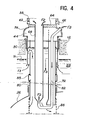
- FIG. 4 is a view comparable to FIG. 3 showing the size of the exchanger after removal of the removable upper part comprising the water inlet 40 and steam outlet 42 chambers, as well as the internal tubes 52 and intermediaries 58 associated with them. It can be seen in FIG. 4 that access to the external tubes 68 is thus completely released.
- This possibility of dismantling the steam generator also has the advantages of facilitating the manufacture of the generator in the factory, its transport, its assembly on site as well as subsequent checks or repairs.
- each of the tube plates is also made possible - by access orifices 41 43 and 45 formed respectively in the dome 46 and in the walls 51 and 62.
- the internal tube 52 has two coaxial walls 52a and 52b defining between them an annular zone 52c.
- this annular zone is closed at its upper end, at the level of the tube plate 48 and open at its lower end. It is therefore filled with water and stagnant steam, which provide satisfactory thermal insulation, especially in the upper part of the bundle in which such insulation is particularly necessary.
- the outer wall 52b of the inner tube 52 extends downward beyond its inner wall 52a, which allows the water reaching the lower end of the tubes to reduce its speed. This reduction in speed is favorable to the change of direction of the water which occurs in the bottom of the intermediate tubes 58.
- the internal tubes 52 also include an internal wall 52a and an external wall 52b separated by an annular zone 52c.
- this annular zone is closed in this case at the lower end of the inner tube 52a, which is also located above the lower end of the outer tube 52b.
- the zone 52c is open upwards at the level of the tube plate 48.
- the dome 46 of the steam generator is deleted and replaced by a cylindrical ferrule that 146 extending upwards the partition 51 and opening at its upper end in the reactor building.
- the zone 52c is therefore filled by a gas at atmospheric pressure and generally by the air which reigns above the steam generator.
- the ferrule 146 supports tube plates 151 to which the inlet pipes 150 are connected.
- the internal walls 52a of the internal tubes 52 extend above the upper tube plate 48, to be connected to the tube plates 151, a number of walls 52a being fixed on each of the plates.
- FIG. 5 a second variant of support for the steam generator has also been shown, in which it is suspended from the slab 12.
- the flared wall 74 has at its lower end a flange 92 which rests on a flange 94 fixed to slab 12 around the opening 38.
- the upper tube plate 48 is crossed by the internal tubes 52, of small diameter. It is at a moderate temperature corresponding to the temperature of the inlet supply water, i.e. about 260 ° C. Finally, it is subjected to an operating pressure corresponding to the pressure drop in the water / steam circuit. The thickness of this plate 48 is therefore moderate.
- the intermediate tube plate 54 is crossed by the intermediate tubes 58 which remain of modest size compared to the pitch of the network.
- This plate is subjected to an average operating pressure corresponding to the pressure difference between helium and vapor, for a moderate temperature of the order of 450 ° C. corresponding to the outlet temperature of the vapor. It is therefore slightly thicker than the tube plate 48.
- the lower tube plate 64 is the only one to be drilled to the diameter of the external tubes 68. It is subjected to temperature and pressure conditions close to those of the intermediate tube plate 54 (differential pressure of approximately 7 MPa and helium outlet temperature substantially below 500 ° C). In fact, it should be noted that the temperature of helium drops by about fifty degrees between the sodium level and the tube plate 64 due to the pursuit over almost three meters of the exchange of helium / vapor heat. . This phenomenon is very favorable to the behavior of the tube plate 64.
- the steam generator 32 used in the reactor according to the invention has a generally cylindrical configuration with a vertical axis.
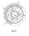
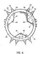
- this layout is produced by providing inside the ferrule 80, of generally cylindrical configuration, three zones 83 for passage of the tubes 72 extending over the entire height of the ferrule, at 120 ° relative to each other.
- These zones 83 of substantially triangular section are delimited by the cylindrical shell 80 and by vertical partitions 81 having a V-shaped section. More precisely, the branches of the V formed in section by each of the partitions 81 are parallel with the adjacent branches of the other two partitions 81.
- the bundle of tubular cells thus presents in section The shape of a three-pointed star. It should be noted that this distribution of the tubes on the plates 48, 54 and 64 is favorable for dimensioning.
- the zones 83 in which they are housed the tubes 72 helium inflows are maintained in an atmosphere corresponding to those of the neutral gas overhead 24 of the reactor.
- This result is obtained by closing off the lower end of each of the zones 83 with a wall leaktightly crossed by the tubes-72.
- these zones 83 can be thermally insulated with respect to the interior of the ferrule 80 by means of appropriate thermal insulation systems (not shown).
- Another solution is to Leave. The sodium flows at reduced speed in these zones by heating the descending helium. These zones hardly differ from the other zones located in the sodium vat.
- the steam generator integrated into the reactor vessel in accordance with the invention therefore has a structure such that all the fluids descending into the main tank are contained in simple tubular structures taken separately, these structures being moderately stressed under well known and highly divided conditions, which considerably reduces the risks associated with cracks and possible leaks.
- a leak detection can be easily carried out, for example by monitoring the atmosphere of neutral gas which is in the steam generator, above the level N ′ of sodium, and in which the helium should result in source of leaks or in the reactor neutral gas sky.
- helium plays the role of thermal damper between these two fluids, which is an important point for reactors with fast neutrons.
- the water / steam circuit comprises a steam pipe 102 by laqueLLe
- the steam outlet pipe 56 of each of the steam generators 32 communicates with the high pressure stage 104a of a steam turbine 104 also comprising a medium pressure stage 104b and a low pressure stage 104c.
- the steam leaving the high pressure stage 104a via a pipe 105 passes through a dryer 106, a medium pressure reheater 108 by steam extraction and a reheater 110 by helium, before being directed to the medium pressure stage 104b of the turbine.
- the steam is directed to the low pressure stage 104c by a pipe 112, before being condensed in a condenser 35.
- the condensed water returns to the inlet pipes 50 of the steam generators 32 through a pipe 116.
- the reheater 110 through which the steam admitted into the medium pressure stage 104b of the turbine simultaneously cools the helium flowing in the intermediate circuit of the steam generators 32.
- the helium circuit consists of a pipe 118 which connects the helium outlet pipes 66 of the steam generators to the inlet of the reheater 110 and a return pipe 120 which connects The outlet of the reheater 110 to the helium inlet pipes 76 of the steam generators.
- the circulation of helium is controlled by a blower 122 placed in the return pipe 120.
- a treatment system 124 and in particular for drying the helium is mounted in parallel on the blower 122.
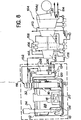
- FIG. 8 Another use of the heat transported by helium is proposed. It is represented in FIG. 8 where we notice a neutral gas circuit integrated in the reactor building and serving for additional heating of the feed water and for additional production of live steam.
- This circuit includes a water heater 126 and a complementary steam generator 128.
- helium in the intermediate circuit of steam generators is particularly interesting. In fact, this gas is chemically neutral and reacts neither with sodium nor with water. In addition, it does not require the use of steels different from those commonly used at operating temperatures. steam generator. Finally, it has good thermal and thermodynamic characteristics. In particular, its thermal conductivity is significantly higher than that of air or carbon dioxide, its specific heat is more than four times that of liquid sodium, but its specific mass is 120 to 150 times lower. Helium can be used on an industrial scale and its flow places little stress on structures. In addition, in the particular case according to the invention, in which the steam generator is integrated in the reactor vessel, it has the advantage of not absorbing the neutrons.
Landscapes
- Engineering & Computer Science (AREA)
- Physics & Mathematics (AREA)
- General Engineering & Computer Science (AREA)
- High Energy & Nuclear Physics (AREA)
- Mechanical Engineering (AREA)
- Combustion & Propulsion (AREA)
- Chemical & Material Sciences (AREA)
- Plasma & Fusion (AREA)
- Life Sciences & Earth Sciences (AREA)
- Sustainable Development (AREA)
- Sustainable Energy (AREA)
- Thermal Sciences (AREA)
- Heat-Exchange Devices With Radiators And Conduit Assemblies (AREA)
- Analysing Materials By The Use Of Radiation (AREA)
Applications Claiming Priority (2)
| Application Number | Priority Date | Filing Date | Title |
|---|---|---|---|
| FR8407332 | 1984-05-11 | ||
| FR8407332A FR2564229B1 (fr) | 1984-05-11 | 1984-05-11 | Reacteur nucleaire a neutrons rapides a generateur de vapeur integre dans la cuve |
Publications (2)
| Publication Number | Publication Date |
|---|---|
| EP0163564A1 true EP0163564A1 (de) | 1985-12-04 |
| EP0163564B1 EP0163564B1 (de) | 1988-07-27 |
Family
ID=9303897
Family Applications (1)
| Application Number | Title | Priority Date | Filing Date |
|---|---|---|---|
| EP85400878A Expired EP0163564B1 (de) | 1984-05-11 | 1985-05-06 | Schneller Neutronenkernreaktor mit Dampferzeuger, integriert im Behälter |
Country Status (5)
| Country | Link |
|---|---|
| US (1) | US4705662A (de) |
| EP (1) | EP0163564B1 (de) |
| JP (1) | JPS60244891A (de) |
| DE (1) | DE3564054D1 (de) |
| FR (1) | FR2564229B1 (de) |
Cited By (6)
| Publication number | Priority date | Publication date | Assignee | Title |
|---|---|---|---|---|
| FR2595459A1 (fr) * | 1986-03-07 | 1987-09-11 | Trepaud Echangeurs | Echangeur thermique a lame de gaz |
| EP0228722A3 (de) * | 1985-12-26 | 1988-10-26 | Stone & Webster Engineering Corporation | Doppelrohrdampferzeuger |
| EP0362155A3 (de) * | 1988-09-27 | 1990-08-22 | ANSALDO S.p.A. | Zwischenwärmeaustauscher eines schnellen Reaktors mit einer erhöhten Rohrplatte, einem Zulaufsiphon und Noteinlassfenster |
| FR2995628A1 (fr) * | 2012-09-19 | 2014-03-21 | Alstom Technology Ltd | Cycle de conversion d'energie par vapeur produite par un reacteur a neutrons rapides refroidi au sodium |
| CN107679272A (zh) * | 2017-08-28 | 2018-02-09 | 中国船舶重工集团公司第七〇九研究所 | 立式蒸汽发生器u型管倒流状态模拟中的传热管分组方法 |
| FR3079959A1 (fr) * | 2018-04-09 | 2019-10-11 | Didier Costes | Reacteur refroidi au sodium en cuve posee, chauffant un gaz pour turbo-alternateur sans circuit intermediaire |
Families Citing this family (6)
| Publication number | Priority date | Publication date | Assignee | Title |
|---|---|---|---|---|
| FR2626709B1 (fr) * | 1988-01-29 | 1992-12-31 | Novatome | Echangeur de chaleur intermediaire d'un reacteur nucleaire a neutrons rapides |
| US7139352B2 (en) * | 1999-12-28 | 2006-11-21 | Kabushiki Kaisha Toshiba | Reactivity control rod for core |
| ITMI20051752A1 (it) * | 2005-09-21 | 2007-03-22 | Ansaldo Energia Spa | Reattore nucleare in particolare reattore nucleare raffreddato a metallo liquido |
| JP2008122248A (ja) * | 2006-11-13 | 2008-05-29 | Toshiba Corp | 高速炉 |
| RU2361302C2 (ru) * | 2007-09-06 | 2009-07-10 | Федеральное государственное унитарное предприятие "Центральный научно-исследовательский институт имени А.Н. Крылова" (ФГУП "ЦНИИ им. акад. А.Н. Крылова") | Способ охлаждения активной зоны быстрого реактора и устройство его осуществления |
| US20120307956A1 (en) | 2010-02-05 | 2012-12-06 | Singh Krishna P | Nuclear reactor system having natural circulation of primary coolant |
Citations (4)
| Publication number | Priority date | Publication date | Assignee | Title |
|---|---|---|---|---|
| FR2015805A1 (de) * | 1968-08-16 | 1970-04-30 | Combustion Eng | |
| FR2055476A5 (de) * | 1969-07-22 | 1971-05-07 | Wheeler Foster Corp | |
| DE2400882A1 (de) * | 1973-02-26 | 1974-08-29 | Combustion Eng | Mantel- und rohrwaermeaustauscher |
| FR2228194A1 (de) * | 1973-02-16 | 1974-11-29 | Hitachi Ltd |
Family Cites Families (5)
| Publication number | Priority date | Publication date | Assignee | Title |
|---|---|---|---|---|
| JPS5139319B2 (de) * | 1972-03-31 | 1976-10-27 | ||
| US4140176A (en) * | 1973-03-26 | 1979-02-20 | The United States Of America As Represented By The United States Department Of Energy | Protective tubes for sodium heated water tubes |
| US3907026A (en) * | 1973-08-21 | 1975-09-23 | Westinghouse Electric Corp | Double tube heat exchanger |
| US3999602A (en) * | 1975-10-21 | 1976-12-28 | The United States Of America As Represented By The United States Energy Research And Development Administration | Matrix heat exchanger including a liquid, thermal couplant |
| US4560533A (en) * | 1984-08-30 | 1985-12-24 | The United States Of America As Represented By The United States Department Of Energy | Fast reactor power plant design having heat pipe heat exchanger |
-
1984
- 1984-05-11 FR FR8407332A patent/FR2564229B1/fr not_active Expired
-
1985
- 1985-05-06 EP EP85400878A patent/EP0163564B1/de not_active Expired
- 1985-05-06 DE DE8585400878T patent/DE3564054D1/de not_active Expired
- 1985-05-10 US US06/732,742 patent/US4705662A/en not_active Expired - Fee Related
- 1985-05-10 JP JP60098137A patent/JPS60244891A/ja active Pending
Patent Citations (4)
| Publication number | Priority date | Publication date | Assignee | Title |
|---|---|---|---|---|
| FR2015805A1 (de) * | 1968-08-16 | 1970-04-30 | Combustion Eng | |
| FR2055476A5 (de) * | 1969-07-22 | 1971-05-07 | Wheeler Foster Corp | |
| FR2228194A1 (de) * | 1973-02-16 | 1974-11-29 | Hitachi Ltd | |
| DE2400882A1 (de) * | 1973-02-26 | 1974-08-29 | Combustion Eng | Mantel- und rohrwaermeaustauscher |
Cited By (9)
| Publication number | Priority date | Publication date | Assignee | Title |
|---|---|---|---|---|
| EP0228722A3 (de) * | 1985-12-26 | 1988-10-26 | Stone & Webster Engineering Corporation | Doppelrohrdampferzeuger |
| FR2595459A1 (fr) * | 1986-03-07 | 1987-09-11 | Trepaud Echangeurs | Echangeur thermique a lame de gaz |
| EP0362155A3 (de) * | 1988-09-27 | 1990-08-22 | ANSALDO S.p.A. | Zwischenwärmeaustauscher eines schnellen Reaktors mit einer erhöhten Rohrplatte, einem Zulaufsiphon und Noteinlassfenster |
| FR2995628A1 (fr) * | 2012-09-19 | 2014-03-21 | Alstom Technology Ltd | Cycle de conversion d'energie par vapeur produite par un reacteur a neutrons rapides refroidi au sodium |
| EP2711508A1 (de) * | 2012-09-19 | 2014-03-26 | Alstom Technology Ltd | Energieumwandlungszyklus für durch einen natriumgekühlten schnellen Neutronenreaktor erzeugten Dampf |
| RU2561839C2 (ru) * | 2012-09-19 | 2015-09-10 | Альстом Текнолоджи Лтд | Цикл преобразования энергии для пара, генерируемого реактором на быстрых нейтронах с натриевым охлаждением |
| CN107679272A (zh) * | 2017-08-28 | 2018-02-09 | 中国船舶重工集团公司第七〇九研究所 | 立式蒸汽发生器u型管倒流状态模拟中的传热管分组方法 |
| CN107679272B (zh) * | 2017-08-28 | 2021-01-08 | 中国船舶重工集团公司第七一九研究所 | 立式蒸汽发生器u型管倒流状态模拟中的传热管分组方法 |
| FR3079959A1 (fr) * | 2018-04-09 | 2019-10-11 | Didier Costes | Reacteur refroidi au sodium en cuve posee, chauffant un gaz pour turbo-alternateur sans circuit intermediaire |
Also Published As
| Publication number | Publication date |
|---|---|
| US4705662A (en) | 1987-11-10 |
| FR2564229B1 (fr) | 1986-09-05 |
| EP0163564B1 (de) | 1988-07-27 |
| DE3564054D1 (en) | 1988-09-01 |
| FR2564229A1 (fr) | 1985-11-15 |
| JPS60244891A (ja) | 1985-12-04 |
Similar Documents
| Publication | Publication Date | Title |
|---|---|---|
| EP0163564B1 (de) | Schneller Neutronenkernreaktor mit Dampferzeuger, integriert im Behälter | |
| EP0688421A1 (de) | Wärmeaustauschvorrichtung und verfahren zur kühlung der aussenwand dieser vorrichtung | |
| EP0246969B1 (de) | Kleiner Druckwasserkernreaktor mit Naturumlauf | |
| EP0147304B1 (de) | Natrium-Wasser-Dampferzeuger mit geraden konzentrischen Rohren und Gaszirkulation in dem ringförmigen Raum | |
| EP0022714A1 (de) | Mit einem Flüssigmetall gekühlter schnelle Neutronen-Kernreaktor mit einem System zum Abführen der Restwärme | |
| EP0068913A1 (de) | Schneller Brüter mit Einrichtung zur Abführung von Restwärme | |
| EP0055643B1 (de) | Kernreaktor, der von einem flüssigen Metall gekühlt wird, das in einem oben angeordnete Verschlüsse aufweisenden Behälter enthalten ist | |
| EP0153225B1 (de) | Wärmetauscher mit einem Notkühlsystem und schneller Kernreaktor mit einem derartigen Wärmetauscher | |
| EP0083545B1 (de) | Sicherheitsvorrichtung zur Ableitung der entstehenden Wärme beim Abschalten eines schnellen Brüters | |
| EP0105781B1 (de) | Sekundärer Kühlkreislauf für einen Flüssigmetall-gekühlten Kernreaktor und Dampferzeuger angepasst an einen solchen Kreislauf | |
| FR2584227A1 (fr) | Dispositif de condensation de vapeur d'eau sous pression et son application au refroidissement d'un reacteur nucleaire apres un incident. | |
| EP0064920B1 (de) | Vorrichtung zur Dampferzeugung und zur Ableitung von Wärme in einem schnellen Brüter | |
| EP0018262A1 (de) | Schneller Kernreaktor mit einem zylindrischen Innenbehälter | |
| EP0258131B1 (de) | Notkühleinrichtung für schnellen Neutronenreaktor | |
| EP0206921B1 (de) | Wärmetauscher mit koaxialen U-Rohren und Zwischenkreislauf von neutralem Gas und schneller Neutronenreaktor mit solchem Wärmetauscher | |
| EP0020264B1 (de) | Wärmetauscher des Teil-Modul-Typs für Kernreaktor | |
| EP0173602A1 (de) | Notwärmetauscher zur Kühlung des Primärmittels eines Kernreaktors und Verfahren zu dessen Zusammenbau | |
| EP0108690B1 (de) | Wärmetauscher für Fluide hoher Temperatur, wobei eines der Fluide an der Oberseite des Wärmetauschers ein- und austritt | |
| EP0117191A1 (de) | Dampferzeuger für einen flüssigmetallgekühlten nuklearen Reaktor | |
| EP0064921A1 (de) | Kühlvorrichtung des Hauptbehälters eines Kernreaktors mit schnellen Neutronen | |
| FR2713752A1 (fr) | Echangeur de chaleur à fluide intermédiaire diphasique. | |
| FR2555794A1 (fr) | Reacteur nucleaire a neutrons rapides equipe de moyens de refroidissement de secours | |
| EP0216667B1 (de) | Rückhaltevorrichtung für eine Flüssigkeit um zu verhindern, dass eine offene, im wesentlichen horizontale Leitung beim Unterschreiten einer bestimmten Zuflussmenge leer läuft | |
| FR2489581A1 (fr) | Reacteur nucleaire a circulation du fluide primaire de refroidissement par convection mixte | |
| EP0161949A1 (de) | Mit flüssigem Metall gekühlter Kernreaktor |
Legal Events
| Date | Code | Title | Description |
|---|---|---|---|
| PUAI | Public reference made under article 153(3) epc to a published international application that has entered the european phase |
Free format text: ORIGINAL CODE: 0009012 |
|
| AK | Designated contracting states |
Designated state(s): BE DE GB IT NL |
|
| 17P | Request for examination filed |
Effective date: 19860509 |
|
| 17Q | First examination report despatched |
Effective date: 19870714 |
|
| RAP1 | Party data changed (applicant data changed or rights of an application transferred) |
Owner name: COMMISSARIAT A L'ENERGIE ATOMIQUE |
|
| GRAA | (expected) grant |
Free format text: ORIGINAL CODE: 0009210 |
|
| AK | Designated contracting states |
Kind code of ref document: B1 Designated state(s): BE DE GB IT NL |
|
| GBT | Gb: translation of ep patent filed (gb section 77(6)(a)/1977) | ||
| REF | Corresponds to: |
Ref document number: 3564054 Country of ref document: DE Date of ref document: 19880901 |
|
| ITF | It: translation for a ep patent filed | ||
| PGFP | Annual fee paid to national office [announced via postgrant information from national office to epo] |
Ref country code: DE Payment date: 19890429 Year of fee payment: 5 |
|
| PGFP | Annual fee paid to national office [announced via postgrant information from national office to epo] |
Ref country code: BE Payment date: 19890502 Year of fee payment: 5 |
|
| PLBE | No opposition filed within time limit |
Free format text: ORIGINAL CODE: 0009261 |
|
| STAA | Information on the status of an ep patent application or granted ep patent |
Free format text: STATUS: NO OPPOSITION FILED WITHIN TIME LIMIT |
|
| ITTA | It: last paid annual fee | ||
| PGFP | Annual fee paid to national office [announced via postgrant information from national office to epo] |
Ref country code: NL Payment date: 19890531 Year of fee payment: 5 Ref country code: GB Payment date: 19890531 Year of fee payment: 5 |
|
| 26N | No opposition filed | ||
| PG25 | Lapsed in a contracting state [announced via postgrant information from national office to epo] |
Ref country code: GB Effective date: 19900506 |
|
| PG25 | Lapsed in a contracting state [announced via postgrant information from national office to epo] |
Ref country code: BE Effective date: 19900531 |
|
| BERE | Be: lapsed |
Owner name: COMMISSARIAT A L'ENERGIE ATOMIQUE Effective date: 19900531 |
|
| PG25 | Lapsed in a contracting state [announced via postgrant information from national office to epo] |
Ref country code: NL Effective date: 19901201 |
|
| GBPC | Gb: european patent ceased through non-payment of renewal fee | ||
| NLV4 | Nl: lapsed or anulled due to non-payment of the annual fee | ||
| PG25 | Lapsed in a contracting state [announced via postgrant information from national office to epo] |
Ref country code: DE Effective date: 19910201 |