EP0153401B1 - Kilowattheuremetre statique - Google Patents
Kilowattheuremetre statique Download PDFInfo
- Publication number
- EP0153401B1 EP0153401B1 EP84903282A EP84903282A EP0153401B1 EP 0153401 B1 EP0153401 B1 EP 0153401B1 EP 84903282 A EP84903282 A EP 84903282A EP 84903282 A EP84903282 A EP 84903282A EP 0153401 B1 EP0153401 B1 EP 0153401B1
- Authority
- EP
- European Patent Office
- Prior art keywords
- voltage
- switch
- multiplicator
- output
- amplifier
- Prior art date
- Legal status (The legal status is an assumption and is not a legal conclusion. Google has not performed a legal analysis and makes no representation as to the accuracy of the status listed.)
- Expired
Links
Images


Classifications
-
- G—PHYSICS
- G01—MEASURING; TESTING
- G01R—MEASURING ELECTRIC VARIABLES; MEASURING MAGNETIC VARIABLES
- G01R21/00—Arrangements for measuring electric power or power factor
- G01R21/127—Arrangements for measuring electric power or power factor by using pulse modulation
Definitions
- the present invention concerns a static kWh meter, according to the preamble of Claim 1.
- Static kWh meters based on a pluse width-pulse height multiplicator, i.e., on a time-chopping multiplicator, are commonly known in the art, and as examples of existing design solutions may be mentioned the U.S. Patents US ⁇ A ⁇ 4,315,212 and US-A-3,794,917.
- the main components of a three-phase meter of this type known in prior art are presented in the block diagram of Figure 1.
- a sample pulse sequence is formed in which the width of the pulses is proportional to the momentary value of the voltage and the height of the pulses is proportional to the momentary value of the current, so that the area subtended by the pulse is proportional to the product of voltage and current, i.e., to the power.
- the sample pulse frequency is selected to be approximately ten times higher than the mains frequency in order to account for superharmonics as well.
- the signal modulating the pulse width modulator 1 is a signal proportional to the mains voltage, produced by the aid of voltage transformers 2.
- the pulse width modulation has usually been carried out by means of an operational amplifier acting as a comparator, to one input terminal thereof being conducted a triangular wave and to the other input terminal a modulating signal proportional to the voltage.
- the threshold level of the comparator is controlled by the modulating voltage, and at the output of the comparator is obtained a square wave having the same frequency as the triangular wave but dependent on the value of the control voltage, as regards its pulse proportions.
- the pulse width-modulated square wave obtained are controlled analog switches 4 in the secondary circuits of the current measuring transformers 3, from their outputs being obtained pulses with a height proportional to the current in the measuring circuit, and which are still modulated by the mains voltage as regards their width.
- the pulses are filtered so as to obtain a d.c. voltage proportional to the power, and this voltage is supplied to a voltage/frequency converter 5.
- the voltage/frequency converter 5 consists of an integrator amplifier integrating the output of the multiplicator and a threshold level detector, which initiates a new cycle when the output of the integrator exceeds the threshold level of the detector.
- the output of the converter delivers a pulse frequency which is proportional to the d.c. voltage supplied thereto, that is to the power, and by which the step motor actuating the counter means 7 of the meter is controlled over a divider unit 6.
- the counter means integrates the power, in other words, it displays the energy consumed.
- a power source 8 is moreover provided, producing the operating voltage from the mains voltage.
- the multiplicator circuits as well as the voltage/frequency converter comprise operational amplifiers the offset voltages of which exert an influence on the result of measurement.
- This objectionable phenomenon is particularly apparent in the product from the voltage/frequency converter when the input voltage of the integrator is low.
- the input voltage may be on the same order of magnitude as the offset voltage of the operator amplifier, whereby quite large errors of the measuring result are possible.
- the offset voltage is a function of time and temperature, thereby interfering with the maintaining of perfect offset voltage compensation in kWh meters of prior art.
- the object of the present invention is to solve the problems stated above and to accomplish a static kWh meter in a simple manner so that the harmful effect of the offset voltage due to the use of an operator amplifer on the accuracy of the voltage/frequency converter will be compensated.
- the task has been accomplished by the features mentioned in the characterising part of Claim 1.
- the integration of the output of the pulse width-pulse height multiplicator is periodically discontinued in the converter circuit producing the frequency signal, and as the integration is discontinued, the offset voltage is stored in the capacitor.
- the capacitor is again connected to the product circuit so that the effect of the offset voltage on the product current is compensated.
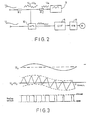
- FIG. 2 is depicted the pulse width-pulse height multiplicator of a static kWh meter.
- the multiplicator comprises a summing circuit and a sampling switch controlled by the summed voltage.
- the summing circuit comprises two resistors R1, R2 joined by one end of each.
- the signal U u which is proportional to the voltage, obtained from the measuring transformer 2 and to the other end of the second resistor R2 is carried the triangular wave U o from the triangular wave oscillator 9.
- the sum voltage U u +U o is obtained at the common point of the summing resistors R1, R2.
- the sampling switch 10 is analog switch receiving a signal U,, proportional to the current intensity from the secondary circuit of the current measuring transformer 3, the control input of said switch being connected to the summing point.
- the analog switch 10 which may for instance be a J-FET or a MOS-FET, changes its state at a given threshold value U thresh of the control voltage.
- the threshold level Uthresh of the analog switch 10then determines the width of the sampling pulse in that the switch is closed when the sum wave U u +U o is higher than the threshold level Ut h res h , and open when the sum wave is lower than the threshold level.
- the output of the sampling switch controlled in such manner will be a square wave sequence in which the width of the pulses is proportional to the voltage and the height is proportional to the current.
- the voltage/frequency converter 5 is controlled.
- FIG. 4 presents the voltage/frequency converter 5 of the meter depicted in Figure 1 and which has been provided with an offset voltage compensating circuit according to the invention.
- the voltage/frequency converter includes, in conventional manner, an operational amplifier 11 connected with the aid of a capacitor C1 and a resistor R3 to serve as integrator, a threshold level detector 12 controlled by the output of the integrator, and a timing circuit 13 whereby a constant current source connected to the output of the integrator is controlled.
- the integrator integrates the input current I in until the output of the integrator exceeds the threshold level U k of the comparator 12, when the timing circuit 13 starts to run and by the aid of a switch 14 switches a feedback current pulse lp for the duration To to the input of the integrator.
- the operating frequency f of the converter is then found by the formula
- the voltage/frequency converter comprises according to the invention, a compensating arrangement which keeps the terminal on the side of the amplifier 11 of the resistor R3, or the point A in Figure 4, at zero level during integration.
- the compensating arrangement comprises a sampling switch K1 connecting the integrator to the multiplicator, a switch K2 in series with the integrating capacitor C1, and a compensating capacitor C2 between the point A and the inverting input of the amplifier 11, a switch K4 connecting the inverting input and the output of the amplifier 11, and a switch K3 grounding the point A.
- the switches K1 and K2 allow the input current I in to be integrated when they are closed in the position as in Figure 4.
- the switches K3 and K4 are open.
- the integration is interrupted between the sampling periods of the sampling switch K1 by opening the switch K2 in series with the integrating capacitor C1.
- the output and inverting input of the amplifier 11 are connected by closing the switch K4, and the other terminal of the capacitor C2 is earthed by closing the switch K3, whereby the offset voltage U os of the amplifier 11 is charged into the compensating capacitor C2.
- the switches K1-K4 are thus controlled to be in the state as presented in Figure 4A.
- the switches K1-K4 are again controlled to be in the state of Figure 4, whereby the compensating capacitor C2 is so connected to the input circuit that during the integration phase the voltage of the point A remains on zero level, which compensates for the effect of the offset voltage on the input current.
- Figure 6 presents the power source unit 8 providing the operating voltage for the circuits of a three-phase meter.
- the power source contains capacitors C3, C4, C5 for reducing the mains voltage U R , U s , U T and rectifying diodes D1-D6 and a filtering capacitor C7 for filtering the voltage supplied to the load 17. Since the circuits of the meter are required to operate also in the case that only one phase carries a voltage, the voltage reducing capacitors have to be dimensioned to be very large, in a conventional rectifying circuit. In order to avoid this, the power source of Figure 6 has moreover been provided with a circuit by the aid of which the current passing through the diodes during the negative half-periods of the phase that has remained live can be utilized.
- This circuit comprises a capacitor C6 which has been connected between the zero lead and the anodes of the rectifying diodes D4-D6 connected together, in series with the diodes D8 and D7 so that it can take up a charge during the negative half-cycles of the live phase through the forward diodes D7, D8.
- the positive terminal of the capacitor C6 has been connected to the positive terminal of the load 17 over the diode D9, and the negative terminal of the capacitor C6 has been connected to the negative terminal of the load over the collector-emitter path of the transistor V1, the base of which has been connected to the common point of the diodes D7 and D4-D6 and over the resistor R4 to the cathodes of the diodes D1-D3.
- the voltage present across the diode D7 when the charging current of the capacitor C6 is flowing keeps the base voltage of the transistor V1 about 0.7V more negative than the emitter voltage, whereby the transistor is not conductive.
- the charging current of the capacitor C6 is interrupted.
- the base voltage of the transistor V1 will then increase to become more positive than the emitter voltage, by effect of the resistor R4.
- the transistor V1 becomes conductive and completes the discharge path of the capacitor C6.
- the charge of the capacitor C6 is discharged through the diode D9 to the capacitor C7 and further to the load 17.
- current is moreover received through the diode D1.
- the discharge current of the capacitor C6 which is added to the said current will approximately double the current going to the load, and this enables the coupling capacitors C3, C4, C5 to be reduced to about one-half and, moreover, reduces the current drawn by the meter from the mains.
Landscapes
- Engineering & Computer Science (AREA)
- Power Engineering (AREA)
- Physics & Mathematics (AREA)
- General Physics & Mathematics (AREA)
- Measurement Of Current Or Voltage (AREA)
- Amplifiers (AREA)
Abstract
Claims (2)
Priority Applications (1)
| Application Number | Priority Date | Filing Date | Title |
|---|---|---|---|
| AT84903282T ATE36076T1 (de) | 1983-08-18 | 1984-08-17 | Statischer kilowattstundenzaehler. |
Applications Claiming Priority (2)
| Application Number | Priority Date | Filing Date | Title |
|---|---|---|---|
| FI832961 | 1983-08-18 | ||
| FI832961A FI67960C (fi) | 1983-08-18 | 1983-08-18 | Kopplingsarrangemang i en statisk kwh-maetare |
Publications (2)
| Publication Number | Publication Date |
|---|---|
| EP0153401A1 EP0153401A1 (fr) | 1985-09-04 |
| EP0153401B1 true EP0153401B1 (fr) | 1988-07-27 |
Family
ID=8517617
Family Applications (1)
| Application Number | Title | Priority Date | Filing Date |
|---|---|---|---|
| EP84903282A Expired EP0153401B1 (fr) | 1983-08-18 | 1984-08-17 | Kilowattheuremetre statique |
Country Status (5)
| Country | Link |
|---|---|
| EP (1) | EP0153401B1 (fr) |
| DE (1) | DE3473045D1 (fr) |
| DK (1) | DK156332C (fr) |
| FI (1) | FI67960C (fr) |
| WO (1) | WO1985000894A1 (fr) |
Families Citing this family (7)
| Publication number | Priority date | Publication date | Assignee | Title |
|---|---|---|---|---|
| ATE66748T1 (de) * | 1986-09-19 | 1991-09-15 | Siemens Ag | Elektronischer elektrizitaetszaehler. |
| US4926131A (en) * | 1987-06-25 | 1990-05-15 | Schlumberger Industries, Inc. | Triangle waveform generator for pulse-width amplitude multiplier |
| US4786877A (en) * | 1987-06-25 | 1988-11-22 | Sangamo-Weston Incorporated | Amplifier for voltage or current to frequency converter |
| US4924412A (en) * | 1987-06-25 | 1990-05-08 | Schlumberger Industries, Inc. | Integrated poly-phase power meter |
| US4910456A (en) * | 1988-12-22 | 1990-03-20 | Asea Brown Boveri Inc. | Electronic watt-hour meter with combined multiplier/integrator circuit |
| GB2243222A (en) * | 1990-04-17 | 1991-10-23 | John Dudding | Drift correction in integrators |
| CN113589033B (zh) * | 2021-07-29 | 2024-08-13 | 昂宝电子(上海)有限公司 | 功率信号检测电路和方法 |
Family Cites Families (4)
| Publication number | Priority date | Publication date | Assignee | Title |
|---|---|---|---|---|
| US3794917A (en) * | 1972-03-09 | 1974-02-26 | Esterline Corp | Electronic watt transducer |
| DE2619734A1 (de) * | 1976-04-30 | 1977-11-17 | Heliowatt Werke | Stromversorgungen fuer elektronische messgeraete |
| JPS581388B2 (ja) * | 1978-07-06 | 1983-01-11 | 株式会社東芝 | 電力量計 |
| US4217546A (en) * | 1978-12-11 | 1980-08-12 | General Electric Company | Electronic energy consumption meter and system with automatic error correction |
-
1983
- 1983-08-18 FI FI832961A patent/FI67960C/fi not_active IP Right Cessation
-
1984
- 1984-08-17 WO PCT/FI1984/000056 patent/WO1985000894A1/fr not_active Ceased
- 1984-08-17 DE DE8484903282T patent/DE3473045D1/de not_active Expired
- 1984-08-17 EP EP84903282A patent/EP0153401B1/fr not_active Expired
-
1985
- 1985-04-17 DK DK173485A patent/DK156332C/da not_active IP Right Cessation
Also Published As
| Publication number | Publication date |
|---|---|
| WO1985000894A1 (fr) | 1985-02-28 |
| EP0153401A1 (fr) | 1985-09-04 |
| FI67960C (fi) | 1985-06-10 |
| DK173485D0 (da) | 1985-04-17 |
| DE3473045D1 (de) | 1988-09-01 |
| DK173485A (da) | 1985-04-17 |
| DK156332C (da) | 1990-01-02 |
| FI832961A0 (fi) | 1983-08-18 |
| DK156332B (da) | 1989-08-07 |
| FI67960B (fi) | 1985-02-28 |
| FI832961A7 (fi) | 1985-02-19 |
Similar Documents
| Publication | Publication Date | Title |
|---|---|---|
| US4495463A (en) | Electronic watt and/or watthour measuring circuit having active load terminated current sensor for sensing current and providing automatic zero-offset of current sensor DC offset error potentials | |
| US4066960A (en) | Electronic kilowatt-hour-meter with error correction | |
| US4182983A (en) | Electronic AC electric energy measuring circuit | |
| US4535287A (en) | Electronic watt/watthour meter with automatic error correction and high frequency digital output | |
| US3955138A (en) | Electronic energy consumption meter with input transformer having single resistance terminated secondary winding coupled to C-MOS switches driven by pulse width modulated control signals | |
| US4217546A (en) | Electronic energy consumption meter and system with automatic error correction | |
| KR840002378B1 (ko) | 전자식 전력량계 | |
| US4092592A (en) | Electronic kWh meter having virtual ground isolation | |
| GB1474236A (en) | Apparatus for metering active electrical energy | |
| US3976942A (en) | Watt/watt hour transducer having current signals and a modulator therefor | |
| US4775834A (en) | Pulse width-pulse height multiplicator in a static kWh meter | |
| EP0153401B1 (fr) | Kilowattheuremetre statique | |
| US4056775A (en) | Electronic kWh meter having internal power supply and error correction system | |
| US4485343A (en) | Electronic watt and watthour meter having analog and digital outputs with automatic error correction | |
| US3959724A (en) | Electronic wattmeter | |
| US4381677A (en) | Reactance measurement circuit | |
| US4275349A (en) | Watt and var transducer | |
| CA1187139A (fr) | Wattmetre electronique a courant de sortie continu proportionnel a la puissance | |
| US4910456A (en) | Electronic watt-hour meter with combined multiplier/integrator circuit | |
| US4707775A (en) | Free running current supply for a monitor | |
| US6178105B1 (en) | Circuit arrangement for accurately detecting a direct current derived from clocked electric input values | |
| CA1136706A (fr) | Compteur electronique de consommation d'energie, et systeme a correction automatique d'erreurs | |
| JP2893763B2 (ja) | 電力トランスデューサ | |
| FI93279B (fi) | Staattinen kWh-mittari | |
| JPH0534385A (ja) | 電力量計 |
Legal Events
| Date | Code | Title | Description |
|---|---|---|---|
| PUAI | Public reference made under article 153(3) epc to a published international application that has entered the european phase |
Free format text: ORIGINAL CODE: 0009012 |
|
| 17P | Request for examination filed |
Effective date: 19850320 |
|
| AK | Designated contracting states |
Designated state(s): AT CH DE FR GB LI NL SE |
|
| 17Q | First examination report despatched |
Effective date: 19870122 |
|
| GRAA | (expected) grant |
Free format text: ORIGINAL CODE: 0009210 |
|
| AK | Designated contracting states |
Kind code of ref document: B1 Designated state(s): AT CH DE FR GB LI NL SE |
|
| REF | Corresponds to: |
Ref document number: 36076 Country of ref document: AT Date of ref document: 19880815 Kind code of ref document: T |
|
| REF | Corresponds to: |
Ref document number: 3473045 Country of ref document: DE Date of ref document: 19880901 |
|
| ET | Fr: translation filed | ||
| PLBI | Opposition filed |
Free format text: ORIGINAL CODE: 0009260 |
|
| 26 | Opposition filed |
Opponent name: AEG AKTIENGESELLSCHAFT, BERLIN UND FRANKFURT Effective date: 19890224 |
|
| NLR1 | Nl: opposition has been filed with the epo |
Opponent name: AEG AG |
|
| PGFP | Annual fee paid to national office [announced via postgrant information from national office to epo] |
Ref country code: GB Payment date: 19900803 Year of fee payment: 7 |
|
| PGFP | Annual fee paid to national office [announced via postgrant information from national office to epo] |
Ref country code: SE Payment date: 19900807 Year of fee payment: 7 |
|
| PGFP | Annual fee paid to national office [announced via postgrant information from national office to epo] |
Ref country code: AT Payment date: 19900813 Year of fee payment: 7 |
|
| PGFP | Annual fee paid to national office [announced via postgrant information from national office to epo] |
Ref country code: FR Payment date: 19900821 Year of fee payment: 7 |
|
| PGFP | Annual fee paid to national office [announced via postgrant information from national office to epo] |
Ref country code: NL Payment date: 19900831 Year of fee payment: 7 |
|
| PGFP | Annual fee paid to national office [announced via postgrant information from national office to epo] |
Ref country code: DE Payment date: 19900928 Year of fee payment: 7 |
|
| PGFP | Annual fee paid to national office [announced via postgrant information from national office to epo] |
Ref country code: CH Payment date: 19901123 Year of fee payment: 7 |
|
| RDAG | Patent revoked |
Free format text: ORIGINAL CODE: 0009271 |
|
| STAA | Information on the status of an ep patent application or granted ep patent |
Free format text: STATUS: PATENT REVOKED |
|
| 27W | Patent revoked |
Effective date: 19900907 |
|
| GBPR | Gb: patent revoked under art. 102 of the ep convention designating the uk as contracting state | ||
| REG | Reference to a national code |
Ref country code: CH Ref legal event code: PL |
|
| NLR2 | Nl: decision of opposition | ||
| EUG | Se: european patent has lapsed |
Ref document number: 84903282.6 Effective date: 19910123 |