EP0153451A1 - Bauteil zum Befestigen eines schwer hartlötbaren Gegenstandes - Google Patents
Bauteil zum Befestigen eines schwer hartlötbaren Gegenstandes Download PDFInfo
- Publication number
- EP0153451A1 EP0153451A1 EP84113208A EP84113208A EP0153451A1 EP 0153451 A1 EP0153451 A1 EP 0153451A1 EP 84113208 A EP84113208 A EP 84113208A EP 84113208 A EP84113208 A EP 84113208A EP 0153451 A1 EP0153451 A1 EP 0153451A1
- Authority
- EP
- European Patent Office
- Prior art keywords
- fixing
- attachment
- difficult
- braze
- substrate
- Prior art date
- Legal status (The legal status is an assumption and is not a legal conclusion. Google has not performed a legal analysis and makes no representation as to the accuracy of the status listed.)
- Withdrawn
Links
Images


Classifications
-
- H—ELECTRICITY
- H05—ELECTRIC TECHNIQUES NOT OTHERWISE PROVIDED FOR
- H05K—PRINTED CIRCUITS; CASINGS OR CONSTRUCTIONAL DETAILS OF ELECTRIC APPARATUS; MANUFACTURE OF ASSEMBLAGES OF ELECTRICAL COMPONENTS
- H05K3/00—Apparatus or processes for manufacturing printed circuits
- H05K3/30—Assembling printed circuits with electric components, e.g. with resistors
- H05K3/32—Assembling printed circuits with electric components, e.g. with resistors electrically connecting electric components or wires to printed circuits
-
- H—ELECTRICITY
- H05—ELECTRIC TECHNIQUES NOT OTHERWISE PROVIDED FOR
- H05K—PRINTED CIRCUITS; CASINGS OR CONSTRUCTIONAL DETAILS OF ELECTRIC APPARATUS; MANUFACTURE OF ASSEMBLAGES OF ELECTRICAL COMPONENTS
- H05K7/00—Constructional details common to different types of electric apparatus
- H05K7/20—Modifications to facilitate cooling, ventilating, or heating
- H05K7/2039—Modifications to facilitate cooling, ventilating, or heating characterised by the heat transfer by conduction from the heat generating element to a dissipating body
- H05K7/20436—Inner thermal coupling elements in heat dissipating housings, e.g. protrusions or depressions integrally formed in the housing
- H05K7/2049—Pressing means used to urge contact, e.g. springs
-
- B—PERFORMING OPERATIONS; TRANSPORTING
- B23—MACHINE TOOLS; METAL-WORKING NOT OTHERWISE PROVIDED FOR
- B23K—SOLDERING OR UNSOLDERING; WELDING; CLADDING OR PLATING BY SOLDERING OR WELDING; CUTTING BY APPLYING HEAT LOCALLY, e.g. FLAME CUTTING; WORKING BY LASER BEAM
- B23K1/00—Soldering, e.g. brazing, or unsoldering
- B23K1/0008—Soldering, e.g. brazing, or unsoldering specially adapted for particular articles or work
- B23K1/0016—Soldering of electronic components
-
- H—ELECTRICITY
- H05—ELECTRIC TECHNIQUES NOT OTHERWISE PROVIDED FOR
- H05K—PRINTED CIRCUITS; CASINGS OR CONSTRUCTIONAL DETAILS OF ELECTRIC APPARATUS; MANUFACTURE OF ASSEMBLAGES OF ELECTRICAL COMPONENTS
- H05K7/00—Constructional details common to different types of electric apparatus
- H05K7/02—Arrangements of circuit components or wiring on supporting structure
- H05K7/12—Resilient or clamping means for holding component to structure
Definitions
- This invention relates to a structure for fixing a portion of a difficult to braze member which is suitable when fixing a member that can not easily be brazed or soldered, such as a heat radiating sheet of an electronic component, to a substrate or the like by brazing or soldering.
- a heating radiating sheet 3 is disposed around an electronic component 2 fitted to a substrate 1 of an electronic appliance or the like, as shown in Figure 1, to cool the electronic component 2.
- This heat radiating sheet 3 must be fixed to the substrate 1.
- aluminum or iron is generally used for the heat radiating sheet 3, these metals can not easily be soft brazed, hard brazed or soldered; nor can they easily be fitted to the substrate 1 by brazing or soldering.
- difficult to braze members must often be fixed to a sheet member such as the substrate 1.
- FIG. 2 illustrates an example of the prior art method of fixing a difficult to braze member such as the heat radiating sheet 3 to the substrate.
- This method has been primarily used to this date, as disclosed in Japanese Utility Model Publication Nos. 50054/1978 and 52590/1978, for example.
- a fixing portion 3a of the heat radiating sheet 3 is inserted into the substrate 1, the tip is bent as shown in the drawing, and is then fixed to the substrate 1 with a screw 4.
- the heat radiating sheet 3 can be fixed by this method, it is by no means easy to fix the sheet to the substrate with the small screw 4. When many heat radiating sheets 3 must be fitted, therefore, considerable time is necessary for fitting.
- Another fixing method is disclosed in Japanese Utility Model Publication No. 32269/1960, not shown.
- This method forms a slit at the fixing portion 3a and fixes the sheet by inserting a clip or the like into the slit, or plates the fixing portion 3a with a brazable material and then brazes or solders the sheet to the substrate 1.
- the former presents a problem in that many man-hours are spent as in the method already described and fixing is not positive, while the latter also presents a problem in that the cost of the work is high, and the plating sometimes peels off the fixing portion and drops onto the substrate, thereby causing short-circuits or making the fixing unstable.
- a heat radiating sheet such as disclosed in U.S. Patent No. 4,054,901 is known, no contrivance has been made in which the fixing method employs a tab.
- the present invention is directed to provide a structure for fixing a portion of a difficult to braze member which can provide reliable fixing and can be put into practice easily and economically.
- the present invention provides a structure for fixing a portion of a difficult to braze member in which an attachment made of a brazable material is fitted to the fixing portion of the difficult to braze member, an anchor portion for anchoring the attachment is formed in the proximity of the fixing portion so as to anchor the attachment to the anchor portion, and the anchor portion is brazed or soldered to a substrate or the like to fix the difficult to braze member.
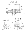
- the fixing portion 3a of a heat radiating sheet 3 is extended in tongue-like form, and an attachment 5 is fitted to this fixing portion.
- the attachment 5 consists of a cylindrical tube such as an eyelet having a flange 5a, and its inner hole 5b is preferably such that the fixing portion 3a can be inserted or fitted thereto.
- copper, brass, solder-plated or tin-plated materials are preferred as the material of the attachment 5, other materials can also be used so long as they can be soft brazed or hard brazed.
- a recess 3b is formed at the root of the fixing portion 3a of the heat radiating sheet 3 so that the flange 5a of the attachment 5 can be fitted to the same.
- a protuberance 3c as an anchor portion is formed at the end portion of the recess 3b as shown in Figure 5. The recess 3b and the protuberance 3c are shaped simultaneously with the fixing portion 3a and the like when the heat radiating sheet 3 is press-molded.
- the attachment 5 is fitted to the fixing portion 3a of the heat radiating sheet 3.
- the flange 5a of the attachment 5 enters the recess 3b.
- the protuberance 3c is bent as indicated by dotted line in Figure 5 so as to anchor the protuberance 3c to the flange 5a.
- the attachment 5 is caulked to the heat radiating sheet 3. Since the attachment is molded in the cylindrical shape as described above, the fixing portion 3a is encompassed by the attachment 5.
- the heat radiating sheet 3 is inserted into the substrate 1, and the attachment 5 and the substrate 1 are joined by solder- ing or brazing, whereby the heat radiating sheet 3 is fixed to the substrate 1 via the attachment 5.
- Brazing or soldering of the substrate 1 is the work that has been practised customarily when assembling electronic components and can be carried out easily and economically without any particular difficulty.
- the attachment 5 itself is not very expensive, and the same or similar attachments can be obtained easily and economically. No problem is encountered when molding the protuberance 3c because it is molded by simultaneous press-molding as described above, and its caulking by bending does not present any problem because the sheet is thin.
- the protuberance 3x is bent after the attachment 5 is inserted into the recess 3b.
- Figure 6 shows another example for fixing the attachment 5.
- a notch is made in the proximity of the end portion of the recess 3b with a chisel or the like to form the anchor portion 6.
- the anchor portion 6 is bent and anchored to the flange 5a of the attachment 5.
- Figure 7 shows another example of the attachment.
- This attachment does not have a flange, but is shaped in a cylindrical, sleevelike form, and the recess 7a is formed at its intermediate portion.
- This attachment 7 is fitted to the fixing portion 3a and the anchor portion 6 and the like is anchored to the recess 7a in the same way as described above, so that the attachment 7 is held in place and is thereafter brazed to the substrate 1 in the same way as described above.
- the protuberance 3c and the anchor portion 6 can be omitted by firmly fitting the attachment 5 or 7 to the fixing portion 3a.
- the present invention can make fixing more reliable and can be worked easily and economically.
Landscapes
- Engineering & Computer Science (AREA)
- Microelectronics & Electronic Packaging (AREA)
- Mechanical Engineering (AREA)
- Physics & Mathematics (AREA)
- Thermal Sciences (AREA)
- Manufacturing & Machinery (AREA)
- Mounting Components In General For Electric Apparatus (AREA)
- Cooling Or The Like Of Electrical Apparatus (AREA)
- Connection Of Plates (AREA)
- Cooling Or The Like Of Semiconductors Or Solid State Devices (AREA)
Applications Claiming Priority (2)
| Application Number | Priority Date | Filing Date | Title |
|---|---|---|---|
| JP23914/84U | 1984-02-23 | ||
| JP1984023914U JPS60137491U (ja) | 1984-02-23 | 1984-02-23 | 難ろう付部材の固定構造 |
Publications (1)
| Publication Number | Publication Date |
|---|---|
| EP0153451A1 true EP0153451A1 (de) | 1985-09-04 |
Family
ID=12123753
Family Applications (1)
| Application Number | Title | Priority Date | Filing Date |
|---|---|---|---|
| EP84113208A Withdrawn EP0153451A1 (de) | 1984-02-23 | 1984-11-02 | Bauteil zum Befestigen eines schwer hartlötbaren Gegenstandes |
Country Status (3)
| Country | Link |
|---|---|
| EP (1) | EP0153451A1 (de) |
| JP (1) | JPS60137491U (de) |
| KR (1) | KR850006298A (de) |
Cited By (3)
| Publication number | Priority date | Publication date | Assignee | Title |
|---|---|---|---|---|
| WO1992003903A1 (de) * | 1990-08-24 | 1992-03-05 | Robert Bosch Gmbh | Verfahren zum herstellen einer lötverbindung und gerät mit derartigen lötverbindungen |
| WO1993014531A1 (fr) * | 1988-12-06 | 1993-07-22 | Kormann Rene Albert | Piece en ceramique et procede de sa fabrication |
| EP1381081A4 (de) * | 2001-04-09 | 2008-02-27 | Sumitomo Metal Smi Electronics | Bga-gehäuse des strahlungstyps und herstellungsverfahren dafür |
Citations (1)
| Publication number | Priority date | Publication date | Assignee | Title |
|---|---|---|---|---|
| GB2032827A (en) * | 1978-09-20 | 1980-05-14 | Bunker Ramo | Method of mounting a lug- receiving and supporting electrical contact |
Family Cites Families (2)
| Publication number | Priority date | Publication date | Assignee | Title |
|---|---|---|---|---|
| JPS53122243A (en) * | 1977-03-31 | 1978-10-25 | Hitachi Ltd | Ventilating fan |
| JPS5843832U (ja) * | 1981-09-07 | 1983-03-24 | トヨタ自動車株式会社 | プレス機におけるプレス型の位置決め治具 |
-
1984
- 1984-02-23 JP JP1984023914U patent/JPS60137491U/ja active Pending
- 1984-10-15 KR KR1019840006417A patent/KR850006298A/ko not_active Ceased
- 1984-11-02 EP EP84113208A patent/EP0153451A1/de not_active Withdrawn
Patent Citations (1)
| Publication number | Priority date | Publication date | Assignee | Title |
|---|---|---|---|---|
| GB2032827A (en) * | 1978-09-20 | 1980-05-14 | Bunker Ramo | Method of mounting a lug- receiving and supporting electrical contact |
Cited By (3)
| Publication number | Priority date | Publication date | Assignee | Title |
|---|---|---|---|---|
| WO1993014531A1 (fr) * | 1988-12-06 | 1993-07-22 | Kormann Rene Albert | Piece en ceramique et procede de sa fabrication |
| WO1992003903A1 (de) * | 1990-08-24 | 1992-03-05 | Robert Bosch Gmbh | Verfahren zum herstellen einer lötverbindung und gerät mit derartigen lötverbindungen |
| EP1381081A4 (de) * | 2001-04-09 | 2008-02-27 | Sumitomo Metal Smi Electronics | Bga-gehäuse des strahlungstyps und herstellungsverfahren dafür |
Also Published As
| Publication number | Publication date |
|---|---|
| KR850006298A (ko) | 1985-10-02 |
| JPS60137491U (ja) | 1985-09-11 |
Similar Documents
| Publication | Publication Date | Title |
|---|---|---|
| EP0250097B1 (de) | Elektrischer Verbinder für leichte Montage auf einer Leiterplatte und Ösen dafür | |
| CA1085941A (en) | Substrate with terminal connections and method of making the same | |
| US4187972A (en) | Apparatus including general purpose desolderer and means for converting the general purpose desolderer to either a soldering iron or a special purpose desolderer | |
| EP0516023A1 (de) | Tragstift-aktivierte Verriegelungsöse | |
| US4575785A (en) | Visual indicator support on a printed circuit | |
| KR900003935B1 (ko) | 마그네트론의 양극 구조체 및 그 제조방법 | |
| US4480384A (en) | Method of attaching a resonator casing to a printed circuit | |
| JPH0960617A (ja) | アルミ板と板金の結合部材及び結合方法 | |
| CA1083196A (en) | Lanced tube joint | |
| US6225572B1 (en) | Connecting an electronic card point to a printed circuit on a metal substrate with a capsule | |
| JP2726203B2 (ja) | チップ型可変抵抗器の製造方法 | |
| JPH07122836A (ja) | ヒートシンク用ハンダ付け端子 | |
| JPH0786086A (ja) | プリント基板実装用電子部品及びその取付方法 | |
| JPS6321104Y2 (de) | ||
| JPS61193727A (ja) | 電子部品の装着方法 | |
| JPH0637482A (ja) | 電子部品組立用治具及びその製造方法 | |
| JPS6241570Y2 (de) | ||
| JPH0218525Y2 (de) | ||
| JPH0356032Y2 (de) | ||
| JPH071044B2 (ja) | 形状記憶合金取付方法および取付具 | |
| JPH04111150U (ja) | リード端子接続構造 | |
| JPH05202725A (ja) | オイルレベルゲージにおける把手部と導入線体の継手構造及びその製造方法 | |
| JPS6118301B2 (de) | ||
| JPS63192296A (ja) | リ−ド線取付方法 | |
| JP2752715B2 (ja) | 口金ピン |
Legal Events
| Date | Code | Title | Description |
|---|---|---|---|
| PUAI | Public reference made under article 153(3) epc to a published international application that has entered the european phase |
Free format text: ORIGINAL CODE: 0009012 |
|
| AK | Designated contracting states |
Designated state(s): DE FR GB NL |
|
| 17P | Request for examination filed |
Effective date: 19860114 |
|
| 17Q | First examination report despatched |
Effective date: 19861201 |
|
| STAA | Information on the status of an ep patent application or granted ep patent |
Free format text: STATUS: THE APPLICATION IS DEEMED TO BE WITHDRAWN |
|
| 18D | Application deemed to be withdrawn |
Effective date: 19870412 |
|
| RIN1 | Information on inventor provided before grant (corrected) |
Inventor name: UMEDA, TERUYUKI |