EP0153557A2 - Appareil à cycle de réfrigération - Google Patents
Appareil à cycle de réfrigération Download PDFInfo
- Publication number
- EP0153557A2 EP0153557A2 EP85100213A EP85100213A EP0153557A2 EP 0153557 A2 EP0153557 A2 EP 0153557A2 EP 85100213 A EP85100213 A EP 85100213A EP 85100213 A EP85100213 A EP 85100213A EP 0153557 A2 EP0153557 A2 EP 0153557A2
- Authority
- EP
- European Patent Office
- Prior art keywords
- compressor
- refrigerant
- refrigeration cycle
- cycle apparatus
- pressure side
- Prior art date
- Legal status (The legal status is an assumption and is not a legal conclusion. Google has not performed a legal analysis and makes no representation as to the accuracy of the status listed.)
- Granted
Links
Images
Classifications
-
- F—MECHANICAL ENGINEERING; LIGHTING; HEATING; WEAPONS; BLASTING
- F25—REFRIGERATION OR COOLING; COMBINED HEATING AND REFRIGERATION SYSTEMS; HEAT PUMP SYSTEMS; MANUFACTURE OR STORAGE OF ICE; LIQUEFACTION SOLIDIFICATION OF GASES
- F25B—REFRIGERATION MACHINES, PLANTS OR SYSTEMS; COMBINED HEATING AND REFRIGERATION SYSTEMS; HEAT PUMP SYSTEMS
- F25B13/00—Compression machines, plants or systems, with reversible cycle
-
- F—MECHANICAL ENGINEERING; LIGHTING; HEATING; WEAPONS; BLASTING
- F25—REFRIGERATION OR COOLING; COMBINED HEATING AND REFRIGERATION SYSTEMS; HEAT PUMP SYSTEMS; MANUFACTURE OR STORAGE OF ICE; LIQUEFACTION SOLIDIFICATION OF GASES
- F25B—REFRIGERATION MACHINES, PLANTS OR SYSTEMS; COMBINED HEATING AND REFRIGERATION SYSTEMS; HEAT PUMP SYSTEMS
- F25B41/00—Fluid-circulation arrangements
- F25B41/20—Disposition of valves, e.g. of on-off valves or flow control valves
- F25B41/24—Arrangement of shut-off valves for disconnecting a part of the refrigerant cycle, e.g. an outdoor part
Definitions
- the present invention relates to refrigerant cycle apparatus.
- a conventional refrigeration cycle apparatus includes a compressor, a condenser, an expansion device such as a capillary tube or an expansion valve, and an evaporator with these components sequentially coupled in series with each other.
- the compressor When the compressor is stopped, the pressure of the refrigerant on a high pressure side is balanced with the pressure of the refrigerant on the low pressure side.
- the compressor As the compressor is started, the difference between the pressures of the high pressure side and the low pressure side is gradually increased until the apparatus is brought to an ordinary operating state.
- the compressor is accordingly repeatedly started and stopped, the high pressure side refrigerant is balanced in presence with the low pressure side refrigerant each time the apparatus is stopped.
- refrigerant liquid stored on the low pressure side in an evaporator is drawn into the compressor.
- the presence of the liquid refrigerant in the condenser increases the load on the compressor at the time of restarting the compressor. This lowers the coefficient of performance (hereinafter abbreviated as "COP") of the apparatus as compared with
- An object of the invention is to simplify the construction of such apparatus thus enabling less expensive manufacture and reduction in size.
- refrigeration cycle apparatus comprising: a compressor, a condenser, an expansion means and an evaporator connected in series with each other; means for repeatedly starting and stopping said compressor; and means for isolating refrigerant on a high pressure side of said compressor from said refrigerant on a low pressure side of said compressor when said compressor is stopped, characterised in that said expansion means comprises at least one capillary tube and in that said isolating means comprises a switching element provided adjacent one said capillary tube adapted to fully close when said compressor is stopped and to fully open when said compressor is started, and a first check valve provided between an outlet of said compressor and an inlet of said condenser.
- Another object of the invention is to enable the expansion coefficient of the apparatus to be varied between the heating and cooling modes in a simple manner.
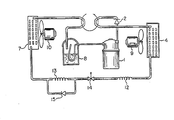
- Reference numeral 1 designates generally a compressor.
- a refrigerant gas compressed at high temperature and high pressure by the compressor 1 is fed through a check valve 2 and a four-way valve 3 into a condenser 4.
- the refrigerant dissipates heat in the condenser 4 and is condensed to a high temperature and high pressure liquid.
- the refrigerant liquid, increased in temperature and pressure by the condenser 4 is passed through a capillary tube 12 where the refrigerant becomes a low temperature, low pressure liquid and a switching element 14 which acts as a valve and from there is introduced into an evaporator 7.
- the low temperature and low pressure refrigerant liquid in the evaporator 7 absorbs heat and thus evaporates to a gas.
- This refrigerant gas is again fed through the four-way valve 3 into an accumulator 8 which isolates the refrigerant liquid which cannot be evaporated in the evaporator 7 and is retained in the liquid state and which returns only the refrigerant gas again to the compressor 1. While the compressor 1 is operating, the apparatus repeats the refrigeration cycle.
- Reference numeral 9 illustrates a fan for the condenser 4 and 10 a fan for the evaporator 7.
- the four-way valve 3 is a change-over or switching valve which operates so that the condenser 4 can be used as an evaporator and the evaporator 7 used as a condenser.
- the evaporator 7 is used as an indoor side heat exchanger
- the condenser 4 is used as an outdoor side heat exchanger.
- the apparatus is operated in a refrigeration cycle which in the heating mode is switched by the four-way valve 3 so that the indoor side heat exchanger 7 is used as a condenser and the outdoor side heat exchanger 4 is used as an evaporator.
- the air temperature conditioning system operates to detect the temperature in the room by a temperature detector or thermostat (not shown) and to start or stop the compressor 1 so as to maintain the room temperature at a set temperature by operating or stopping the refrigeration cycle apparatus.
- the switching element 14, which isolates the compressor 1, is constructed so as to open when the compressor 1 is started and to close when the compressor 1 is stopped.
- the element 14 and the check valve 2 function to isolate high pressure side refrigerant and low pressure side refrigerant when the compressor 1 is stopped.
- the high pressure side refrigerant in the refrigeration cycle is isolated from the low pressure side refrigerant. Since the element 14 is then opened, a desired pressure difference between the high and low pressure side refrigerant can be attained in short time and the apparatus can reach the ordinary operating state in short time.
- the conventional refrigerant cycle not incorporating such an isolating device requires about five minutes to reach the ordinary operation state after restarting.
- the refrigeration cycle apparatus of the invention requires only about one minute and twenty seconds to make the transition.
- the aforesaid switching element 14 may be a solenoid valve 5 or another type of switching valve and may be any type which closes when the compressor 1 is stopped and opens when the compressor 1 is started.
- a further capillary tube 13 in parallel with a check valve 15 which is constructed to pass the refrigerant in the illustrated cooling mode and to block the refrigerant in the non-illustrated heat ' ing mode with the valve 3 switched to its other position.
- the check valve 15 is provided to effectively alter the length of the total capillary tube 12, 13 since the apparatus will operate more efficiently if the expansion coefficient of the refrigerant is varied between the cooling mode and the heating mode in such a manner that the capillary tube is effectively increased in length in the heating mode.
- the apparatus can be inexpensively constructed, even if the check valve 15 is added.
- the switching element 14 is constructed to compare the pressure P 2 , determined by the output side refrigerant gas temperature of the evaporator 7 as detected by a heat sensitive tube provided between the outlet of the evaporator 7 and the inlet of the compressor 1, with the pressure P 1 of the refrigerant exhausted from the capillary tube 12, and to open when P 2 > P 1 and to close when P 2 ⁇ P 1 , in the same manner as described above.
Landscapes
- Engineering & Computer Science (AREA)
- Physics & Mathematics (AREA)
- Mechanical Engineering (AREA)
- Thermal Sciences (AREA)
- General Engineering & Computer Science (AREA)
- Compression-Type Refrigeration Machines With Reversible Cycles (AREA)
Priority Applications (2)
| Application Number | Priority Date | Filing Date | Title |
|---|---|---|---|
| EP85100213A EP0153557B1 (fr) | 1981-10-20 | 1981-10-20 | Appareil à cycle de réfrigération |
| EP87109204A EP0247638B1 (fr) | 1981-10-20 | 1981-10-20 | Appareil à cycle de réfrigération |
Applications Claiming Priority (1)
| Application Number | Priority Date | Filing Date | Title |
|---|---|---|---|
| EP85100213A EP0153557B1 (fr) | 1981-10-20 | 1981-10-20 | Appareil à cycle de réfrigération |
Related Parent Applications (1)
| Application Number | Title | Priority Date | Filing Date |
|---|---|---|---|
| EP81108580.2 Division | 1981-10-20 |
Publications (3)
| Publication Number | Publication Date |
|---|---|
| EP0153557A2 true EP0153557A2 (fr) | 1985-09-04 |
| EP0153557A3 EP0153557A3 (en) | 1986-02-19 |
| EP0153557B1 EP0153557B1 (fr) | 1989-05-17 |
Family
ID=8193223
Family Applications (1)
| Application Number | Title | Priority Date | Filing Date |
|---|---|---|---|
| EP85100213A Expired EP0153557B1 (fr) | 1981-10-20 | 1981-10-20 | Appareil à cycle de réfrigération |
Country Status (1)
| Country | Link |
|---|---|
| EP (1) | EP0153557B1 (fr) |
Cited By (2)
| Publication number | Priority date | Publication date | Assignee | Title |
|---|---|---|---|---|
| US5564280A (en) * | 1994-06-06 | 1996-10-15 | Schilling; Ronald W. | Apparatus and method for refrigerant fluid leak prevention |
| US5651267A (en) * | 1993-02-09 | 1997-07-29 | Empresa Brasileira De Compressores S/A - Embraco | Starting arrangement for small refrigeration systems |
Family Cites Families (7)
| Publication number | Priority date | Publication date | Assignee | Title |
|---|---|---|---|---|
| FR811326A (fr) * | 1936-01-21 | 1937-04-12 | Sulzer Ag | Machine frigorifique à compression |
| US2720756A (en) * | 1954-12-29 | 1955-10-18 | Gen Electric | Heat pump, including fixed flow control means |
| US2969655A (en) * | 1959-05-19 | 1961-01-31 | Ranco Inc | Reversible heat pump system |
| US3093976A (en) * | 1962-04-20 | 1963-06-18 | Carl O Walcutt | Refrigeration system including receiver |
| US3131549A (en) * | 1962-11-29 | 1964-05-05 | Carrier Corp | Heat pump control |
| US4081971A (en) * | 1976-09-17 | 1978-04-04 | The Trane Company | Air cooled centrifugal refrigeration machine with provision to prevent evaporator freezing |
| US4267702A (en) * | 1979-08-13 | 1981-05-19 | Ranco Incorporated | Refrigeration system with refrigerant flow controlling valve |
-
1981
- 1981-10-20 EP EP85100213A patent/EP0153557B1/fr not_active Expired
Cited By (2)
| Publication number | Priority date | Publication date | Assignee | Title |
|---|---|---|---|---|
| US5651267A (en) * | 1993-02-09 | 1997-07-29 | Empresa Brasileira De Compressores S/A - Embraco | Starting arrangement for small refrigeration systems |
| US5564280A (en) * | 1994-06-06 | 1996-10-15 | Schilling; Ronald W. | Apparatus and method for refrigerant fluid leak prevention |
Also Published As
| Publication number | Publication date |
|---|---|
| EP0153557A3 (en) | 1986-02-19 |
| EP0153557B1 (fr) | 1989-05-17 |
Similar Documents
| Publication | Publication Date | Title |
|---|---|---|
| KR930002429B1 (ko) | 냉동싸이클 장치 | |
| JP3341404B2 (ja) | 空気調和装置の運転制御装置 | |
| JPH04295566A (ja) | エンジン駆動式空気調和機 | |
| US4516408A (en) | Refrigeration system for refrigerant heating type air conditioning apparatus | |
| JP3291753B2 (ja) | 冷凍装置の冷媒充填量検知装置 | |
| JP3467837B2 (ja) | 空気調和装置 | |
| JP2002081769A (ja) | 空気調和機 | |
| JPH04222353A (ja) | 空気調和装置の運転制御装置 | |
| EP0077414B1 (fr) | Système de conditionnement d'air | |
| EP0153557A2 (fr) | Appareil à cycle de réfrigération | |
| JPH10205933A (ja) | 空気調和機 | |
| EP0247638B1 (fr) | Appareil à cycle de réfrigération | |
| JP2001280749A (ja) | 冷凍装置 | |
| JP2003106689A (ja) | 空気調和機 | |
| JPH02290471A (ja) | 空気調和機 | |
| JP2955401B2 (ja) | 空気調和機 | |
| JPH07243726A (ja) | 二元冷却装置 | |
| JPH03170758A (ja) | 空気調和装置 | |
| JPS6346350B2 (fr) | ||
| JP2999763B2 (ja) | マルチ型の空気調和機 | |
| JP3291886B2 (ja) | 空調装置およびその制御方法 | |
| JP3231393B2 (ja) | 冷暖房装置 | |
| JP2512072B2 (ja) | 空気調和機の冷凍サイクル | |
| JPH10141798A (ja) | ヒ−トポンプ装置 | |
| JPH0772647B2 (ja) | 空気調和機の均圧装置 |
Legal Events
| Date | Code | Title | Description |
|---|---|---|---|
| PUAI | Public reference made under article 153(3) epc to a published international application that has entered the european phase |
Free format text: ORIGINAL CODE: 0009012 |
|
| AC | Divisional application: reference to earlier application |
Ref document number: 77414 Country of ref document: EP |
|
| AK | Designated contracting states |
Designated state(s): DE FR GB IT |
|
| PUAL | Search report despatched |
Free format text: ORIGINAL CODE: 0009013 |
|
| AK | Designated contracting states |
Designated state(s): DE FR GB IT |
|
| 17P | Request for examination filed |
Effective date: 19860414 |
|
| 17Q | First examination report despatched |
Effective date: 19860826 |
|
| GRAA | (expected) grant |
Free format text: ORIGINAL CODE: 0009210 |
|
| AC | Divisional application: reference to earlier application |
Ref document number: 77414 Country of ref document: EP |
|
| AK | Designated contracting states |
Kind code of ref document: B1 Designated state(s): DE FR GB IT |
|
| REF | Corresponds to: |
Ref document number: 3177054 Country of ref document: DE Date of ref document: 19890622 |
|
| ITF | It: translation for a ep patent filed | ||
| ET | Fr: translation filed | ||
| PLBI | Opposition filed |
Free format text: ORIGINAL CODE: 0009260 |
|
| 26 | Opposition filed |
Opponent name: KKW KULMBACHER KLIMAGERAETE-WERK GMBH Effective date: 19900215 |
|
| PLAB | Opposition data, opponent's data or that of the opponent's representative modified |
Free format text: ORIGINAL CODE: 0009299OPPO |
|
| R26 | Opposition filed (corrected) |
Opponent name: KKW KULMBACHER KLIMAGERAETE-WERK GMBH Effective date: 19900215 |
|
| PLBN | Opposition rejected |
Free format text: ORIGINAL CODE: 0009273 |
|
| STAA | Information on the status of an ep patent application or granted ep patent |
Free format text: STATUS: OPPOSITION REJECTED |
|
| 27O | Opposition rejected |
Effective date: 19910308 |
|
| ITTA | It: last paid annual fee | ||
| ITPR | It: changes in ownership of a european patent |
Owner name: OFFERTA DI LICENZA AL PUBBLICO |
|
| REG | Reference to a national code |
Ref country code: GB Ref legal event code: 746 Effective date: 19960611 |
|
| REG | Reference to a national code |
Ref country code: FR Ref legal event code: D6 |
|
| PGFP | Annual fee paid to national office [announced via postgrant information from national office to epo] |
Ref country code: FR Payment date: 19991011 Year of fee payment: 19 |
|
| PGFP | Annual fee paid to national office [announced via postgrant information from national office to epo] |
Ref country code: GB Payment date: 19991020 Year of fee payment: 19 |
|
| PGFP | Annual fee paid to national office [announced via postgrant information from national office to epo] |
Ref country code: DE Payment date: 19991022 Year of fee payment: 19 |
|
| PG25 | Lapsed in a contracting state [announced via postgrant information from national office to epo] |
Ref country code: GB Free format text: LAPSE BECAUSE OF NON-PAYMENT OF DUE FEES Effective date: 20001020 |
|
| GBPC | Gb: european patent ceased through non-payment of renewal fee |
Effective date: 20001020 |
|
| PG25 | Lapsed in a contracting state [announced via postgrant information from national office to epo] |
Ref country code: FR Free format text: LAPSE BECAUSE OF NON-PAYMENT OF DUE FEES Effective date: 20010629 |
|
| PG25 | Lapsed in a contracting state [announced via postgrant information from national office to epo] |
Ref country code: DE Free format text: LAPSE BECAUSE OF NON-PAYMENT OF DUE FEES Effective date: 20010703 |
|
| REG | Reference to a national code |
Ref country code: FR Ref legal event code: ST |