EP0153592A2 - Fermeture à aiguille à action commandée pour buses d'injection de moules d'injection - Google Patents
Fermeture à aiguille à action commandée pour buses d'injection de moules d'injection Download PDFInfo
- Publication number
- EP0153592A2 EP0153592A2 EP85100808A EP85100808A EP0153592A2 EP 0153592 A2 EP0153592 A2 EP 0153592A2 EP 85100808 A EP85100808 A EP 85100808A EP 85100808 A EP85100808 A EP 85100808A EP 0153592 A2 EP0153592 A2 EP 0153592A2
- Authority
- EP
- European Patent Office
- Prior art keywords
- piston
- needle
- bore
- locking
- plate
- Prior art date
- Legal status (The legal status is an assumption and is not a legal conclusion. Google has not performed a legal analysis and makes no representation as to the accuracy of the status listed.)
- Granted
Links
Images
Classifications
-
- B—PERFORMING OPERATIONS; TRANSPORTING
- B29—WORKING OF PLASTICS; WORKING OF SUBSTANCES IN A PLASTIC STATE IN GENERAL
- B29C—SHAPING OR JOINING OF PLASTICS; SHAPING OF MATERIAL IN A PLASTIC STATE, NOT OTHERWISE PROVIDED FOR; AFTER-TREATMENT OF THE SHAPED PRODUCTS, e.g. REPAIRING
- B29C45/00—Injection moulding, i.e. forcing the required volume of moulding material through a nozzle into a closed mould; Apparatus therefor
- B29C45/17—Component parts, details or accessories; Auxiliary operations
- B29C45/26—Moulds
- B29C45/27—Sprue channels ; Runner channels or runner nozzles
- B29C45/28—Closure devices therefor
- B29C45/2806—Closure devices therefor consisting of needle valve systems
- B29C45/281—Drive means therefor
Definitions
- the invention relates to a positively controlled needle closure for spray nozzles in injection molding molds, in which the closure needle engages with its end facing away from the spray nozzle into a bore in the piston provided on both sides with piston rod attachments of a drive cylinder which can be acted upon with a pressure medium and is fastened in this.
- the piston is provided with a through bore which is provided with an internally threaded section starting from the end of the outer piston rod attachment which is accessible from the outside.
- the locking needle itself is provided with an external thread at its rear end and can be screwed into the piston from the outside. The opening and closing force is transferred via the thread. With the help of the thread is an axial Adjustment of the locking needle in the piston possible. Locking takes place via a lock nut, which rests on the face against the outer piston rod shoulder.
- a needle valve is also known in which the piston of the hydraulic cylinder is provided on one side with a piston rod extension.
- the locking needle is in this case provided at its rear end with a cylindrical head which lies in a counterbore extending from the rear end of the piston and is held therein by a threaded plug. The closing force and the opening force are transmitted to the locking needle through the threaded plug and the annular shoulder at the bottom of the countersink.
- the injection heads are each provided with separate electrical heating elements. Additional heating elements are provided in the distributor plate.
- the heating elements are duck in injection molds Verschl sandwichele E. They are therefore subject to periodic inspections.
- the hot runner area must be exposed to perform these inspections.
- the plate in or on which the individual drive cylinders are attached must be detached from the rest of the shape.
- the plate carrying the drive cylinder can only be dismantled together with the locking needles in the known needle locks with a one-sided piston rod attachment if the drive cylinders have not been individually dismantled beforehand and the needles with the pistons are removed.
- the locking needles can be removed to the outside.
- an assembly space of at least the length of the locking needles is required here. In both cases, the hot runner must be dismantled be heated.
- the object of the invention is to provide a valve gate of the type mentioned in such a way that simple disassembly and reassembly for carrying out inspection work or for eliminating errors of all kinds is possible without heating the mold.
- a stop effective in the closing direction is provided for the outer end of the locking needle in the piston bore, and in that a screw can be screwed into a threaded bore in the end of the locking needle from the outer end of the outer piston rod attachment effective stop in the opening direction.
- a particular advantage of the needle valve according to the invention can also be seen in the fact that during the disassembly and reassembly the drive cylinders, which are normally designed as hydraulic cylinders, do not need to be opened themselves and thus oil contamination is avoided.
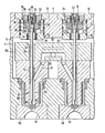
- two plates 2, 4 of a multiple injection mold which are fastened detachably to one another are shown, which abut one another in plane 6 and can be separated from one another in this plane.
- the two plates 2 and 4 normally belong to the machine-fixed part of the injection mold.
- the plate 2 can be a mounting plate at the same time.
- Hydraulic cylinders 8 are arranged in the plate 2 and are inserted into bores 10. The attachment takes place in each case with the aid of a mounting flange 12 embedded in the plate 2.
- the hydraulic cylinder 8 is provided with a piston 14 which can be acted upon on both sides and which is provided on both sides with a piston rod extension 16 or 18.
- the cylinder is provided in one piece on the inside with a cylinder cover 20.
- a cylinder cover 22 is provided on the outside, which is provided on the outside with a thread 24 with which it can be screwed into a threaded bore 2E against a stop 28.
- Piston rod seals are arranged in the cylinder covers 20 and 22 in the usual way.
- the hydraulic cylinder is provided with connections 30, 32, which lead to ring channels on the circumference of the cylinder, which are connected in a known manner to channels in the plate 2, which are not shown in the drawing.
- the ring channels are sealed against each other in the bore 10 via 0-rings.
- a bore 34 extending from the end of the inner piston rod extension 16, which ends in front of an annular shoulder 36, which here in the region of the outer piston rod extension 18 lies.
- the fastening end 38 of a locking needle 40 engages in this bore.
- the bore 34 is formed such that the fastening end 38 of the locking needle is guided radially. In the remaining section of the bore 34, the locking needle 40 is not guided radially.
- a countersunk bore 42 is provided, the bottom of which likewise forms an annular shoulder 44.
- a bore 46 is provided through which a screw 48, preferably designed as an Allen screw, can be screwed into an axial threaded bore 50 in the fastening end 38 of the locking needle.
- the spray heads 52 are accommodated in corresponding bores in a known manner. These spray heads are provided with a hot runner 54, through which the locking needle 40 is guided in the center and engages with its locking part 56 in a sprue ring 58. From the opposite side of the plate 4 are embedded in these shaped elements 59, which is provided on the outside with a mold cavity 61 in the form of a spherical cap, as is used in the production of so-called preforms.
- the hot runner 54 is heated by an electrical heating element 60 which encloses this area on the outside.
- the hot runner 54 is connected to a feed channel 62 which is led obliquely to it, which in turn is connected to a ground channel 64 in a distributor plate 66.
- this distributor plate 66 further heating elements 68 are provided, one of which is shown schematically.
- the locking needles 40 are passed through holes 70 with a diameter larger than that of the fastening end 38 through the plate 66. They are guided in guide bushes 72 in the spray heads 52.
- injection mold need not be described for the explanation of the invention. For example, they can be designed in the manner described in DE-OS 31 40 711.
- the spray heads 52 are inserted into the plate 4 of the mold and the distributor plate 66 is mounted thereon.
- the closure needles 40 can then be used.
- the plate 2 is then assembled, and the plate 2 can be assembled without difficulty even in the case of a multiple mold, for example a mold with 16 individual molds, as is typical for a preform injection mold.
- the locking needles slide in the piston 14 over the wide area of the bore 34 in the area of this bore in which they are guided radially. After the plate 2 has been fastened to the plate 4, the screws 48 are then inserted and tightened.
- the locking needles can of course also be connected to the pistons beforehand.
- the machine is used to carry out maintenance and repair work on an injection mold mounted in the injection molding machine movable part of the mold, which is not shown in the drawing, locked when the mold is closed with the machine-fixed part of the mold and the plate 2 released from the clamping on the injection molding machine.
- the injection molding machine is then operated open.
- the plate 2 is accessible from the fastening side.
- To remove the plate 2 the screws 48 to the individual locking needles 40 and then the fastenings between the plates 2 and 4 are loosened.
- the plate 2 can then be removed, the locking needles remaining. This work is carried out with the heating switched off.
- the needles are therefore stuck in the plastic that has solidified in the hot runner 54.
- the distributor plate 66 After removing the plate, the distributor plate 66 is freely accessible and can also be removed without difficulty. After removal of the distributor plate, the individual spray heads 52 with the locking needles 40 are then exposed and are taken out of the plate 4, inspected and, if necessary, repaired or replaced.
- the locking needles for removing the plate 2 and the distributor plate 66 are only required in the axial direction, which corresponds to the immersion depth of the fastening end of the locking needles in the piston 14.
- a space corresponding to the distance between the fastening side of the plate 2 and the closure end 56 of the closure needles 40 does not need to be made available, as in the known designs.
- valve gate can be carried out in a simple manner maintenance and repair work in the area of the distributor plate and the spray heads including their valve needles on the mold mounted in the injection molding machine. This also contributes to the fact that extremely short operational interruptions for maintenance or repair can be achieved.
Landscapes
- Engineering & Computer Science (AREA)
- Manufacturing & Machinery (AREA)
- Mechanical Engineering (AREA)
- Injection Moulding Of Plastics Or The Like (AREA)
- Infusion, Injection, And Reservoir Apparatuses (AREA)
- Moulds For Moulding Plastics Or The Like (AREA)
- Nozzles (AREA)
- Fuel-Injection Apparatus (AREA)
Priority Applications (1)
| Application Number | Priority Date | Filing Date | Title |
|---|---|---|---|
| AT85100808T ATE66406T1 (de) | 1984-02-02 | 1985-01-26 | Zwangsgesteuerter nadelverschluss fuer spritzduesen in spritzgiessformen. |
Applications Claiming Priority (2)
| Application Number | Priority Date | Filing Date | Title |
|---|---|---|---|
| DE3403603A DE3403603C2 (de) | 1984-02-02 | 1984-02-02 | Zwangsgesteuerter Nadelverschluß für Spritzdüsen in Spritzgießformen |
| DE3403603 | 1984-02-02 |
Publications (3)
| Publication Number | Publication Date |
|---|---|
| EP0153592A2 true EP0153592A2 (fr) | 1985-09-04 |
| EP0153592A3 EP0153592A3 (en) | 1988-01-20 |
| EP0153592B1 EP0153592B1 (fr) | 1991-08-21 |
Family
ID=6226567
Family Applications (1)
| Application Number | Title | Priority Date | Filing Date |
|---|---|---|---|
| EP85100808A Expired - Lifetime EP0153592B1 (fr) | 1984-02-02 | 1985-01-26 | Fermeture à aiguille à action commandée pour buses d'injection de moules d'injection |
Country Status (6)
| Country | Link |
|---|---|
| EP (1) | EP0153592B1 (fr) |
| JP (1) | JPS60247527A (fr) |
| AT (1) | ATE66406T1 (fr) |
| DE (2) | DE3403603C2 (fr) |
| ES (1) | ES295780Y (fr) |
| PT (1) | PT79920B (fr) |
Cited By (8)
| Publication number | Priority date | Publication date | Assignee | Title |
|---|---|---|---|---|
| EP0264724A3 (en) * | 1986-10-20 | 1989-08-16 | Mold-Masters Limited | Mechanism for valve gated injection molding with resilient retaining ring |
| WO1990009876A1 (fr) * | 1989-02-23 | 1990-09-07 | Kurt Paul Cuttat | Obturateur et unite dotee de cet obturateur pour moules d'injection |
| EP0558932A1 (fr) * | 1992-02-29 | 1993-09-08 | Otto Männer | Buse multiple à fermeture à aiguille pour moules d'injection |
| EP0558931A1 (fr) * | 1992-02-29 | 1993-09-08 | Otto Männer | Buse à fermeture à aiguille avec entraînement à piston |
| EP1367664A3 (fr) * | 2002-04-14 | 2004-06-09 | Sgl Carbon Ag | Plaque bipolaire pour cellule électrochimique |
| EP1648681A4 (fr) * | 2003-06-23 | 2008-07-02 | Panos Trakas | Ensemble tige de soupape reglable ameliore, et procede |
| US7955071B1 (en) * | 2009-11-30 | 2011-06-07 | Dme Company Llc | Apparatus for injection molding |
| EP2633971A1 (fr) * | 2012-03-01 | 2013-09-04 | Günther Heisskanaltechnik GmbH | Buse de moulage par injection avec aiguille d'obturation guidée par manchon de guidage et dispositif de moulage par injection en étant équipé |
Families Citing this family (12)
| Publication number | Priority date | Publication date | Assignee | Title |
|---|---|---|---|---|
| DE3641416A1 (de) * | 1986-12-04 | 1988-06-09 | Guenter Strueh | Vorrichtung und verfahren zur verarbeitung pastoeser, aushaertbarer medien |
| DE3642343C2 (de) * | 1986-12-11 | 1997-05-28 | Arnaldo Dipl Ing Glaeser | Vorrichtung zum gleichzeitigen Anspritzen mehrerer Formteile in einem Spritzwerkzeug |
| DE3833220C2 (de) * | 1988-09-30 | 1998-04-30 | Agfa Gevaert Ag | Nadelverschlußdüse in einem Spritzgießwerkzeug zur Verarbeitung thermoplastischer Kunststoffe |
| JPH0767715B2 (ja) * | 1990-11-20 | 1995-07-26 | 三晶技研株式会社 | ホットランナ式合成樹脂金型 |
| JPH05293852A (ja) * | 1992-04-22 | 1993-11-09 | Japan Steel Works Ltd:The | 射出成形機用ノズル孔の調節方法および射出成形機用ノズル |
| DE29809855U1 (de) | 1998-06-03 | 1998-08-20 | Günther Heißkanaltechnik GmbH, 35066 Frankenberg | Nadelverschlußdüse |
| DE20302845U1 (de) | 2003-02-20 | 2003-05-22 | Günther GmbH & Co., Metallverarbeitung, 35066 Frankenberg | Nadelverschlußdüse |
| US7618253B2 (en) | 2007-10-19 | 2009-11-17 | Mold-Masters (2007) Limited | Multiple-gate injection molding apparatus |
| US8091202B2 (en) | 2009-05-06 | 2012-01-10 | Synventive Molding Solutions, Inc. | Method and apparatus for coupling and uncoupling an injection valve pin |
| DE102009024271B4 (de) * | 2009-06-05 | 2017-05-24 | Psg Plastic Service Gmbh | Betätigungsvorrichtung für eine Nadelverschlussdüse |
| DE102012104291B4 (de) | 2012-05-16 | 2014-07-10 | Günther Heisskanaltechnik Gmbh | Düsenmundstück für eine Spritzgießdüse, Spritzgießdüse und Spritzgießwerkzeug |
| DE102016106745A1 (de) | 2016-04-12 | 2017-10-12 | Günther Heisskanaltechnik Gmbh | Führungsbuchse für eine Spritzgießvorrichtung |
Citations (3)
| Publication number | Priority date | Publication date | Assignee | Title |
|---|---|---|---|---|
| DE2919862A1 (de) | 1978-06-06 | 1979-12-20 | Continental Group | Spritzgusseinheit |
| EP0021273A1 (fr) | 1979-06-12 | 1981-01-07 | Hendrikus Jacobus Elisabeth Schouenberg | Mécanisme d'injection pour mouler des matières plastiques |
| DE3140711A1 (de) | 1981-10-14 | 1983-04-28 | Maschinenfabrik Köppern GmbH & Co KG, 4320 Hattingen | Mehrfachspritzgiesswerkzeug |
Family Cites Families (5)
| Publication number | Priority date | Publication date | Assignee | Title |
|---|---|---|---|---|
| US3500501A (en) * | 1968-01-30 | 1970-03-17 | Cincinnati Milling Machine Co | Nozzle shut-off device |
| US4268240A (en) * | 1978-01-06 | 1981-05-19 | Husky Injection Molding Systems | Actuating mechanism for gate valve of injection nozzle |
| US4279582A (en) * | 1979-04-02 | 1981-07-21 | Incoe Corporation | Method and apparatus for individual control of injection mold shut-off bushings |
| EP0076980B1 (fr) * | 1981-10-14 | 1986-08-27 | Fried. Krupp Gesellschaft mit beschränkter Haftung | Moule d'injection multiple |
| CA1193818A (fr) * | 1983-03-24 | 1985-09-24 | Jobst U. Gellert | Systeme de moulage par injection avec commande hydraulique a raccordements alternes |
-
1984
- 1984-02-02 DE DE3403603A patent/DE3403603C2/de not_active Expired
-
1985
- 1985-01-26 EP EP85100808A patent/EP0153592B1/fr not_active Expired - Lifetime
- 1985-01-26 AT AT85100808T patent/ATE66406T1/de not_active IP Right Cessation
- 1985-01-26 DE DE8585100808T patent/DE3583807D1/de not_active Expired - Fee Related
- 1985-02-01 PT PT79920A patent/PT79920B/pt unknown
- 1985-02-01 JP JP60016736A patent/JPS60247527A/ja active Pending
- 1985-02-01 ES ES1985295780U patent/ES295780Y/es not_active Expired
Patent Citations (3)
| Publication number | Priority date | Publication date | Assignee | Title |
|---|---|---|---|---|
| DE2919862A1 (de) | 1978-06-06 | 1979-12-20 | Continental Group | Spritzgusseinheit |
| EP0021273A1 (fr) | 1979-06-12 | 1981-01-07 | Hendrikus Jacobus Elisabeth Schouenberg | Mécanisme d'injection pour mouler des matières plastiques |
| DE3140711A1 (de) | 1981-10-14 | 1983-04-28 | Maschinenfabrik Köppern GmbH & Co KG, 4320 Hattingen | Mehrfachspritzgiesswerkzeug |
Cited By (9)
| Publication number | Priority date | Publication date | Assignee | Title |
|---|---|---|---|---|
| EP0264724A3 (en) * | 1986-10-20 | 1989-08-16 | Mold-Masters Limited | Mechanism for valve gated injection molding with resilient retaining ring |
| WO1990009876A1 (fr) * | 1989-02-23 | 1990-09-07 | Kurt Paul Cuttat | Obturateur et unite dotee de cet obturateur pour moules d'injection |
| EP0558932A1 (fr) * | 1992-02-29 | 1993-09-08 | Otto Männer | Buse multiple à fermeture à aiguille pour moules d'injection |
| EP0558931A1 (fr) * | 1992-02-29 | 1993-09-08 | Otto Männer | Buse à fermeture à aiguille avec entraînement à piston |
| EP1367664A3 (fr) * | 2002-04-14 | 2004-06-09 | Sgl Carbon Ag | Plaque bipolaire pour cellule électrochimique |
| EP1648681A4 (fr) * | 2003-06-23 | 2008-07-02 | Panos Trakas | Ensemble tige de soupape reglable ameliore, et procede |
| USRE41280E1 (en) | 2003-06-23 | 2010-04-27 | Panos Trakas | Adjustable valve pin assembly |
| US7955071B1 (en) * | 2009-11-30 | 2011-06-07 | Dme Company Llc | Apparatus for injection molding |
| EP2633971A1 (fr) * | 2012-03-01 | 2013-09-04 | Günther Heisskanaltechnik GmbH | Buse de moulage par injection avec aiguille d'obturation guidée par manchon de guidage et dispositif de moulage par injection en étant équipé |
Also Published As
| Publication number | Publication date |
|---|---|
| JPS60247527A (ja) | 1985-12-07 |
| ATE66406T1 (de) | 1991-09-15 |
| ES295780Y (es) | 1987-12-16 |
| ES295780U (es) | 1987-06-16 |
| DE3403603A1 (de) | 1985-08-14 |
| PT79920B (de) | 1986-09-11 |
| EP0153592B1 (fr) | 1991-08-21 |
| DE3403603C2 (de) | 1985-12-05 |
| EP0153592A3 (en) | 1988-01-20 |
| PT79920A (de) | 1985-03-01 |
| DE3583807D1 (de) | 1991-09-26 |
Similar Documents
| Publication | Publication Date | Title |
|---|---|---|
| EP0153592B1 (fr) | Fermeture à aiguille à action commandée pour buses d'injection de moules d'injection | |
| DE19516793B4 (de) | Spritzgießdüsenanordnung und Spritzgießvorrichtung | |
| EP3231577B1 (fr) | Dispositif de moulage par soufflage | |
| EP0635350B1 (fr) | Dispositif de commande pneumatique pour des valves à aiguille de canal chauffant pour moules d'injection | |
| DE69106348T2 (de) | Düse für eine Spritzgussmaschine. | |
| EP0558931B1 (fr) | Buse à fermeture à aiguille avec entraînement à piston | |
| DE2728820B2 (de) | Verschlußdüse für eine Kunststoff -Spritzgießmaschine | |
| WO2018091499A1 (fr) | Élément d'outil et outil et procédé d'élèvement d'un insert de moule d'un élément d'outil | |
| DE19606568A1 (de) | Vorrichtung und Verfahren zum Spannen einer Spritzgießform | |
| DE68912946T2 (de) | Einspritzdüse zum einspritzen von kunststoffen, härtbaren harzen oder kautschuk. | |
| EP3117977B1 (fr) | Moitie d'outil pour un moule de formage d'une machine a mouler par injection comprenant un systeme de canaux chauffants | |
| EP0925902B1 (fr) | Moule d'injection | |
| DE2340499B1 (de) | Mehrteilige Schnecke für eine Schnekkenstrangpresse zur Verarbeitung von Kunststoffen | |
| DE3534937C2 (fr) | ||
| DE3336203A1 (de) | Spritzgiess- oder presswerkzeug zur verarbeitung von kunststoffmassen | |
| EP0595200B1 (fr) | Dispositif de couplage pour une machine de moulage de matières plastiques par injection | |
| EP0585671A1 (fr) | Unité d'éjection pour machines à mouler par injection | |
| DE1804640B1 (de) | Spritzkopf zur Herstellung von Kunststoffrohren oder -schlaeuchen | |
| DE2143132A1 (de) | Formwerkzeug, insbesondere fuer die fertigung von teilen aus duromerkunststoffen | |
| DE19524803C1 (de) | Schnellspanneinrichtung, insbesondere für Spritzgußwerkzeuge | |
| DE3140837A1 (de) | Druckgiessmaschine | |
| DE102005015242B4 (de) | Heißkanalverteilerblock für den Anschluß an eine Spritzgießmaschine | |
| DE3307590C2 (de) | Auswerfersystem für teilbare Formen | |
| DE19733257C2 (de) | Rundklinkenzug | |
| DE1113805B (de) | Aus zwei gegeneinander bewegbaren, mehrteiligen Haelften bestehende Form, insbesondere fuer Spritzgussmaschinen zur Verarbeitung thermoplastischer Kunststoffe |
Legal Events
| Date | Code | Title | Description |
|---|---|---|---|
| PUAI | Public reference made under article 153(3) epc to a published international application that has entered the european phase |
Free format text: ORIGINAL CODE: 0009012 |
|
| AK | Designated contracting states |
Designated state(s): AT BE CH DE FR GB IT LI NL SE |
|
| RAP1 | Party data changed (applicant data changed or rights of an application transferred) |
Owner name: FRIED. KRUPP GESELLSCHAFT MIT BESCHRAENKTER HAFTUN |
|
| PUAL | Search report despatched |
Free format text: ORIGINAL CODE: 0009013 |
|
| AK | Designated contracting states |
Kind code of ref document: A3 Designated state(s): AT BE CH DE FR GB IT LI NL SE |
|
| 17P | Request for examination filed |
Effective date: 19880707 |
|
| 17Q | First examination report despatched |
Effective date: 19900216 |
|
| GRAA | (expected) grant |
Free format text: ORIGINAL CODE: 0009210 |
|
| AK | Designated contracting states |
Kind code of ref document: B1 Designated state(s): AT BE CH DE FR GB IT LI NL SE |
|
| REF | Corresponds to: |
Ref document number: 66406 Country of ref document: AT Date of ref document: 19910915 Kind code of ref document: T |
|
| ET | Fr: translation filed | ||
| REF | Corresponds to: |
Ref document number: 3583807 Country of ref document: DE Date of ref document: 19910926 |
|
| GBT | Gb: translation of ep patent filed (gb section 77(6)(a)/1977) | ||
| ITF | It: translation for a ep patent filed | ||
| PLBE | No opposition filed within time limit |
Free format text: ORIGINAL CODE: 0009261 |
|
| 26N | No opposition filed | ||
| PGFP | Annual fee paid to national office [announced via postgrant information from national office to epo] |
Ref country code: GB Payment date: 19921207 Year of fee payment: 9 |
|
| PGFP | Annual fee paid to national office [announced via postgrant information from national office to epo] |
Ref country code: FR Payment date: 19921209 Year of fee payment: 9 |
|
| PGFP | Annual fee paid to national office [announced via postgrant information from national office to epo] |
Ref country code: SE Payment date: 19921216 Year of fee payment: 9 |
|
| PGFP | Annual fee paid to national office [announced via postgrant information from national office to epo] |
Ref country code: BE Payment date: 19930113 Year of fee payment: 9 |
|
| PGFP | Annual fee paid to national office [announced via postgrant information from national office to epo] |
Ref country code: AT Payment date: 19930127 Year of fee payment: 9 |
|
| PG25 | Lapsed in a contracting state [announced via postgrant information from national office to epo] |
Ref country code: GB Effective date: 19940126 Ref country code: AT Effective date: 19940126 |
|
| PG25 | Lapsed in a contracting state [announced via postgrant information from national office to epo] |
Ref country code: SE Effective date: 19940127 |
|
| PG25 | Lapsed in a contracting state [announced via postgrant information from national office to epo] |
Ref country code: BE Effective date: 19940131 |
|
| BERE | Be: lapsed |
Owner name: FRIED. KRUPP G.M.B.H. Effective date: 19940131 |
|
| GBPC | Gb: european patent ceased through non-payment of renewal fee |
Effective date: 19940126 |
|
| PG25 | Lapsed in a contracting state [announced via postgrant information from national office to epo] |
Ref country code: FR Effective date: 19940930 |
|
| REG | Reference to a national code |
Ref country code: FR Ref legal event code: ST |
|
| EUG | Se: european patent has lapsed |
Ref document number: 85100808.6 Effective date: 19940810 |
|
| PGFP | Annual fee paid to national office [announced via postgrant information from national office to epo] |
Ref country code: DE Payment date: 19981214 Year of fee payment: 15 |
|
| PGFP | Annual fee paid to national office [announced via postgrant information from national office to epo] |
Ref country code: NL Payment date: 19990128 Year of fee payment: 15 Ref country code: CH Payment date: 19990128 Year of fee payment: 15 |
|
| PG25 | Lapsed in a contracting state [announced via postgrant information from national office to epo] |
Ref country code: LI Free format text: LAPSE BECAUSE OF NON-PAYMENT OF DUE FEES Effective date: 20000131 Ref country code: CH Free format text: LAPSE BECAUSE OF NON-PAYMENT OF DUE FEES Effective date: 20000131 |
|
| PG25 | Lapsed in a contracting state [announced via postgrant information from national office to epo] |
Ref country code: NL Free format text: LAPSE BECAUSE OF NON-PAYMENT OF DUE FEES Effective date: 20000801 |
|
| REG | Reference to a national code |
Ref country code: CH Ref legal event code: PL |
|
| NLV4 | Nl: lapsed or anulled due to non-payment of the annual fee |
Effective date: 20000801 |
|
| PG25 | Lapsed in a contracting state [announced via postgrant information from national office to epo] |
Ref country code: DE Free format text: LAPSE BECAUSE OF NON-PAYMENT OF DUE FEES Effective date: 20001101 |