EP0153676A1 - Magnetooptisches Aufzeichnungssystem - Google Patents
Magnetooptisches Aufzeichnungssystem Download PDFInfo
- Publication number
- EP0153676A1 EP0153676A1 EP85101702A EP85101702A EP0153676A1 EP 0153676 A1 EP0153676 A1 EP 0153676A1 EP 85101702 A EP85101702 A EP 85101702A EP 85101702 A EP85101702 A EP 85101702A EP 0153676 A1 EP0153676 A1 EP 0153676A1
- Authority
- EP
- European Patent Office
- Prior art keywords
- storage medium
- magnetization
- magnetic field
- magneto
- actuator
- Prior art date
- Legal status (The legal status is an assumption and is not a legal conclusion. Google has not performed a legal analysis and makes no representation as to the accuracy of the status listed.)
- Granted
Links
- 230000005415 magnetization Effects 0.000 claims abstract description 41
- 230000015654 memory Effects 0.000 claims abstract description 17
- 230000003287 optical effect Effects 0.000 claims abstract description 10
- 230000010287 polarization Effects 0.000 abstract description 4
- 239000010408 film Substances 0.000 description 25
- 238000010586 diagram Methods 0.000 description 7
- 239000000758 substrate Substances 0.000 description 5
- XEEYBQQBJWHFJM-UHFFFAOYSA-N iron Substances [Fe] XEEYBQQBJWHFJM-UHFFFAOYSA-N 0.000 description 2
- 229910052688 Gadolinium Inorganic materials 0.000 description 1
- 235000010627 Phaseolus vulgaris Nutrition 0.000 description 1
- 244000046052 Phaseolus vulgaris Species 0.000 description 1
- 229910052771 Terbium Inorganic materials 0.000 description 1
- 238000010521 absorption reaction Methods 0.000 description 1
- 229910000808 amorphous metal alloy Inorganic materials 0.000 description 1
- 230000001447 compensatory effect Effects 0.000 description 1
- 238000010276 construction Methods 0.000 description 1
- 230000007423 decrease Effects 0.000 description 1
- 238000005516 engineering process Methods 0.000 description 1
- 239000011521 glass Substances 0.000 description 1
- 229910052742 iron Inorganic materials 0.000 description 1
- 238000000034 method Methods 0.000 description 1
- 229910052761 rare earth metal Inorganic materials 0.000 description 1
- 239000010409 thin film Substances 0.000 description 1
- 229910052723 transition metal Inorganic materials 0.000 description 1
- 150000003624 transition metals Chemical class 0.000 description 1
Images


Classifications
-
- G—PHYSICS
- G11—INFORMATION STORAGE
- G11C—STATIC STORES
- G11C13/00—Digital stores characterised by the use of storage elements not covered by groups G11C11/00, G11C23/00, or G11C25/00
- G11C13/04—Digital stores characterised by the use of storage elements not covered by groups G11C11/00, G11C23/00, or G11C25/00 using optical elements ; using other beam accessed elements, e.g. electron or ion beam
- G11C13/06—Digital stores characterised by the use of storage elements not covered by groups G11C11/00, G11C23/00, or G11C25/00 using optical elements ; using other beam accessed elements, e.g. electron or ion beam using magneto-optical elements
-
- G—PHYSICS
- G11—INFORMATION STORAGE
- G11B—INFORMATION STORAGE BASED ON RELATIVE MOVEMENT BETWEEN RECORD CARRIER AND TRANSDUCER
- G11B11/00—Recording on or reproducing from the same record carrier wherein for these two operations the methods are covered by different main groups of groups G11B3/00 - G11B7/00 or by different subgroups of group G11B9/00; Record carriers therefor
- G11B11/10—Recording on or reproducing from the same record carrier wherein for these two operations the methods are covered by different main groups of groups G11B3/00 - G11B7/00 or by different subgroups of group G11B9/00; Record carriers therefor using recording by magnetic means or other means for magnetisation or demagnetisation of a record carrier, e.g. light induced spin magnetisation; Demagnetisation by thermal or stress means in the presence or not of an orienting magnetic field
- G11B11/105—Recording on or reproducing from the same record carrier wherein for these two operations the methods are covered by different main groups of groups G11B3/00 - G11B7/00 or by different subgroups of group G11B9/00; Record carriers therefor using recording by magnetic means or other means for magnetisation or demagnetisation of a record carrier, e.g. light induced spin magnetisation; Demagnetisation by thermal or stress means in the presence or not of an orienting magnetic field using a beam of light or a magnetic field for recording by change of magnetisation and a beam of light for reproducing, i.e. magneto-optical, e.g. light-induced thermomagnetic recording, spin magnetisation recording, Kerr or Faraday effect reproducing
- G11B11/10532—Heads
- G11B11/10534—Heads for recording by magnetising, demagnetising or transfer of magnetisation, by radiation, e.g. for thermomagnetic recording
- G11B11/10536—Heads for recording by magnetising, demagnetising or transfer of magnetisation, by radiation, e.g. for thermomagnetic recording using thermic beams, e.g. lasers
-
- G—PHYSICS
- G11—INFORMATION STORAGE
- G11B—INFORMATION STORAGE BASED ON RELATIVE MOVEMENT BETWEEN RECORD CARRIER AND TRANSDUCER
- G11B11/00—Recording on or reproducing from the same record carrier wherein for these two operations the methods are covered by different main groups of groups G11B3/00 - G11B7/00 or by different subgroups of group G11B9/00; Record carriers therefor
- G11B11/10—Recording on or reproducing from the same record carrier wherein for these two operations the methods are covered by different main groups of groups G11B3/00 - G11B7/00 or by different subgroups of group G11B9/00; Record carriers therefor using recording by magnetic means or other means for magnetisation or demagnetisation of a record carrier, e.g. light induced spin magnetisation; Demagnetisation by thermal or stress means in the presence or not of an orienting magnetic field
Definitions
- the present invention relates to magneto-optical file memories, and more particularly to a magneto-optical file memory capable of rewriting information.
- a magneto-optical disk device wherein a storage medium having a magnetic film is irradiated with a laser bean. The direction of magnetization of this film is reversed by the resulting absorption of photon energy, thereby to write and/or erase information. The rotation of the polarization plane of light reflected from the storage medium is detected, thereby to reproduce the re- corded information (cf. Y. TOGAMI et al:, "Amorphous thin film disk for magneto-optical memory", SPIE, vol. 329, Optical Disk Technology (1982), pp. 208 - 214).
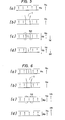
- Fig. 1 illustrates the principle of the writing operation.
- (a) shows unidirectional magnetization Ms before storage in a magnetic film. The state in which the magnetic film is magnetized in one direction in this manner is set as the state of initial magnetization.
- (b) shows that, when the surface of the magnetic film is irradiated with a laser beam 1 in the form of a spot, the minute part is heated to or above the temperature of the Curie point until the coercive force and the magnetization become null.
- (c) shows a state resulting when a magnetic field for writing Hb (about 8000 A/m) is applied to the state (b) in the direction opposite to that of the magnetization Ms.
- Fig. 2. shows the state (d) explained in Fig. 1.
- Fig. 1 shows the state (corresponding to (b) in Fig. 1) in which the written minute part is irradiated with a laser beam in the form of a spot and heated to or above the temperature of the Curie point.
- (c) shows a state resulting when a magnetic field for erasing Hb (about 16000 A/m) is applied to the state (b) in the same direction as that of the magnetization Ms.
- (d) shows the state of the magnetization Ms stable in the cooled condition of the minute part (at the room temperature). The erasing is performed in the above way.
- An object of the present invention is to eliminate the disadvantage of the prior-art magneto-optical file memory as stated above, and to provide a magnetic file memory capable of writing and erasing information precisely.
- the inventors have found out that the aforementioned disadvantage is attributed to the actuator, namely, that the written - and erased states of information in the magnetic film of the storage medium are governed by the magnitude and direction of a leakage magnetic field from the actuator, and the present invention is characterized in that, in consideration of the influence of the leakage magnetic field of the actuator, the sense of the leakage magnetic field and the sense of the initial magnetization of the magnetic film of the storage medium are set to be identical.
- FIG. 3 is a schematic arrangement diagram illustrative for one embodiment of a magneto-optical file memory according to the present invention.
- the storage medium 17 consists of a transparent substrate 17a (for example, a glass substrate) and a magnetic film 17b (for example, an amorphous alloy film which is made of a rare-earth element such as Gd or Tb and a transition metal such as Fe or Co and which is about lbo nm thick).
- the laser beam is condensed as the minute spot on the magnetic film 17b through the transparent substrate 17a.
- the lens 15 is assembled in an actuator 16 so that the condensed beam spot may track the motion of the storage medium 17.
- first and second stationary yokes 102 and 102' are coupled to a permanent magnet 101, to construct a magnetic circuit which forms a closed magnetic path as indicated by arrows A.
- the arm 104' of a movable holder 104 for holding the focusing lens 15 is inserted in the gap between the first and second stationary yokes 102 and 102'.
- a coil 103 is wound round the arm 104' of the movable holder 104, and this movable holder is moved in the direction of an arrow B by causing current to flow through the coil 103.
- the movable holder 104 is supported on the stationary yokes 102 and 102' by a leaf spring 105.
- the position of the lens 15 can be adjusted by controlling the current flowing through the coil 103, so that the laser beam can be projected in the form of the predetermined spot on the storage medium fluttering vertically. The direction in which the permanent magnet is mounted can be determined at will.
- the permanent magnet 101 is arranged in a direction corresponding to the direction of the optical axis of the lens 15, so that the leakage magnetic field Ha of the permanent magnet 101 arises in parallel with the optical axis.
- the distance between the actuator and the storage medium is about 2 mm, and the value of the leakage magnetic field Ha interlinked with the storage medium is as large as approximately 8000 A/mon the storage medium. Accordingly, the leakage magnetic field of the actuator affects an external magnetic field which is applied when information is written or erased.
- the laser beam of the laser 11 (the power of which is lower in the reproducing mode than in the writing or erasing mode) is condensed on the magnetic film 17b.
- Light reflected from the magnetic film 17b shows a very small rotation of the polarization plane relative to the polarization plane of the light emitted by the laser 11.
- the direction of the rotation (clockwise or counterclockwise) is determined by the sense of the magnetization of the magnetic film 17b.
- the reflected light passes through the focusing lens 15 again and is reflected by the galvano-mirror 14 as well as the semitransparent mirror 13, whereupon it incides on a semitransparent mirror 19.
- Light transmitted here passes through a convex lens 20 as well as a cylindrical lens 21 and incides on a quadri photodetector 22.
- a defocusing signal and a tracking signal are obtained on the basis of an output signal from the photodetector 22 (a method of deriving the defocusing signal and the tracking signal is detailed in the official gazette of Japanese Patent Application Publication No. 54-41883, for example).
- These control signals are feed
- Fig. 5 is a diagram for explaining the writing operation of the magneto-optical file memory according to the present invention.
- Fig. 5 shows the magnetization Ms of the magnetic film 17b and the leakage magnetic field Ha of the actuator 16.
- the senses of Ha and Ms are set to be identical.
- (b) shows a state in which the laser beam 1 is projected as a spot on the surface of the film so as to heat the minute part to the temperature of or above the Curie point.
- (c) shows a state resulting when the writing magnetic field Hb is applied to the film in state (b).
- (d) shows a reversed magnetization state (written domain) which is stable in the cooled condition of the minute part (at the room temperature).
- Fig. 6 is a diagram for explaining the erasing operation according to the present invention.
- Fig. 6 shows the state explained at (d) in Fig. 5.
- the magnetization Ms in the unwritten condition is initialized so as to have the same sense as that of Ha.
- (b) shows a state in which the written minute part is irradiated with the laser beam 1 in the form of the spot and is heated to the temperature of or above the Curie point.
- (c) shows a state in which the erasing magnetic field Hb is applied.
- (d) shows the state of the magnetization Ms which is stable in the cooled condition of the minute part (at the room temperature).
- the erasing magnetic field Hf 1 of great magnitude can be attained by exploiting the leakage magnetic field Ha skillfully. Since, as mentioned before, the mode of erasing information requires an effective magnetic field several times higher than that in the writing mode, the magnitudes of the magnetic fields to be generated by the magnet coil must be considered with reference to that in the erasing mode. According to the present invention, the leakage magnetic field Ha is added in the erasing mode, and hence, the magnetic field to be generated by the magnet coil may be small, with the result that the magnet coil can be rendered small in size and light in weight.
- Fig. 7 shows an electromagnet which generates a magnetic field in the order of 800 k A/ m.
- the electromagnet is composed of coils 201, 201' and iron cores 202, 202'.
- the sense of the magnetic field can be determined at will by controlling the senses of currents to flow through the coils 201, 201'.
- the direction of the magnetic field is set to a fixed sense as indicated in Fig. 7, and the storage medium with the substrate 17a and the magnetic film 17b combined unitarily is inserted in this magnetic field, to set the initial magnetization so that the direction of the magnetization Ms of the magnetic film 17b may become perpendicular to the surface of the substrate.
- the storage medium which has had the direction of the magnetization Ms of the magnetic film 17b thus preset is disposed so that this direction of the magnetization agrees with the direction of the leakage magnetic field Ha of the actuator, whereby the leakage magnetic field Ha can be effectively utilized in writing and erasing information as described before.
- the precise writing and erasing of information are possible, and moreover, storage domains can be made smaller to attain a higher density of storage.
Landscapes
- Physics & Mathematics (AREA)
- Optics & Photonics (AREA)
- Recording Or Reproducing By Magnetic Means (AREA)
Applications Claiming Priority (2)
| Application Number | Priority Date | Filing Date | Title |
|---|---|---|---|
| JP59025032A JPH065585B2 (ja) | 1984-02-15 | 1984-02-15 | 光磁気記憶装置 |
| JP25032/84 | 1984-02-15 |
Publications (2)
| Publication Number | Publication Date |
|---|---|
| EP0153676A1 true EP0153676A1 (de) | 1985-09-04 |
| EP0153676B1 EP0153676B1 (de) | 1989-01-25 |
Family
ID=12154567
Family Applications (1)
| Application Number | Title | Priority Date | Filing Date |
|---|---|---|---|
| EP85101702A Expired EP0153676B1 (de) | 1984-02-15 | 1985-02-15 | Magnetooptisches Aufzeichnungssystem |
Country Status (6)
| Country | Link |
|---|---|
| US (1) | US4672594A (de) |
| EP (1) | EP0153676B1 (de) |
| JP (1) | JPH065585B2 (de) |
| KR (1) | KR920010029B1 (de) |
| CA (1) | CA1230677A (de) |
| DE (1) | DE3567983D1 (de) |
Cited By (10)
| Publication number | Priority date | Publication date | Assignee | Title |
|---|---|---|---|---|
| GB2181879A (en) * | 1985-09-13 | 1987-04-29 | Canon Kk | Magneto-optical information recording apparatus |
| EP0241222A1 (de) * | 1986-04-10 | 1987-10-14 | Canon Kabushiki Kaisha | Opto-magnetisches Aufzeichnungsgerät mit aufeinanderfolgendem Antrieb von optischem Kopf und Magnetfeldpolarisation |
| EP0179671A3 (en) * | 1984-10-26 | 1988-03-30 | Nec Corporation | Apparatus for magneto-optically recording, reproducing and erasing data |
| DE3804733A1 (de) * | 1987-03-06 | 1988-09-15 | Hitachi Ltd | Magneto-optische speichereinrichtung |
| US4789972A (en) * | 1986-12-22 | 1988-12-06 | International Business Machines Corporation | Selectively controlling the erasure in a magneto-optic recording medium |
| US4916680A (en) * | 1986-12-22 | 1990-04-10 | International Business Machines Corporation | Magnetooptic recording member having selectively-reversed erasure directions in predetermined recording areas of the record member |
| US4937800A (en) * | 1986-12-22 | 1990-06-26 | International Business Machines Corporation | Method of recording using selective-erasure directions for magnetooptic record members |
| EP0286070A3 (en) * | 1987-04-10 | 1990-09-12 | Fujitsu Limited | A magnetic bias coil of a magneto-optical recording apparatus |
| US4959820A (en) * | 1986-04-22 | 1990-09-25 | Sony Corporation | Magnetooptical recording apparatus with constant leakage magnetic and pulse modulated magnetic field |
| US5020041A (en) * | 1987-03-06 | 1991-05-28 | Hitachi, Ltd. | Magneto-optical memory apparatus having a floating magnetic head |
Families Citing this family (19)
| Publication number | Priority date | Publication date | Assignee | Title |
|---|---|---|---|---|
| CA1277767C (en) * | 1986-03-19 | 1990-12-11 | Kenji Torazawa | Optical recording apparatus |
| JP2570270B2 (ja) * | 1986-10-08 | 1997-01-08 | 株式会社ニコン | ツービームによる光磁気記録方法及び装置 |
| JP2637415B2 (ja) * | 1987-03-03 | 1997-08-06 | オリンパス光学工業株式会社 | 光磁気記録再生装置 |
| JPS63273242A (ja) * | 1987-04-30 | 1988-11-10 | Oki Electric Ind Co Ltd | 光磁気デイスクの書込み、消去方法 |
| JP2754537B2 (ja) * | 1987-05-18 | 1998-05-20 | 株式会社ニコン | 光磁気記録媒体並びにそれを使用したビット形成方法 |
| JPH088282Y2 (ja) * | 1988-04-06 | 1996-03-06 | 日産自動車株式会社 | 内燃機関のv型シリンダブロック |
| US4977540A (en) * | 1988-06-22 | 1990-12-11 | The Regents Of The University Of California | Spin glass type associative processor system |
| US5343448A (en) * | 1988-07-20 | 1994-08-30 | Sharp Kabushiki Kaiasha | External magnetic field device for a magnetooptical information recording and reproducing apparatus |
| US5276663A (en) * | 1989-04-17 | 1994-01-04 | Canon Kabushiki Kaisha | Optical information recording-reproducing apparatus including a condensing lens secured to a lens barrel |
| JPH03113758A (ja) * | 1989-09-22 | 1991-05-15 | Pioneer Electron Corp | 光磁気ディスクプレーヤ |
| JPH03113757A (ja) * | 1989-09-22 | 1991-05-15 | Pioneer Electron Corp | 光磁気ディスクプレーヤ |
| JPH07118106B2 (ja) * | 1990-03-08 | 1995-12-18 | パイオニア株式会社 | 光磁気記録再生装置 |
| JP2877889B2 (ja) * | 1990-04-13 | 1999-04-05 | パイオニア株式会社 | 光磁気記録再生装置 |
| US5202863A (en) * | 1990-09-11 | 1993-04-13 | Matsushita Electric Industrial Co., Ltd. | Magneto-optical disk unit compatible with different two types of magneto-optical disks and a magnetic-field generator suitable thereof |
| US5485437A (en) * | 1993-02-05 | 1996-01-16 | Discovision Associates | Shock-resistant, electrostatically actuated pick-up for optical recording and playback |
| GB2293264B (en) * | 1994-09-01 | 1998-05-27 | Asahi Optical Co Ltd | Magneto-optical disk apparatus |
| JPH07176100A (ja) * | 1994-10-27 | 1995-07-14 | Sony Corp | 光磁気記録装置 |
| JP3070516B2 (ja) * | 1997-04-28 | 2000-07-31 | 日本電気株式会社 | 光ディスク装置 |
| JP2004022137A (ja) | 2002-06-19 | 2004-01-22 | Sony Corp | ディスク状記録媒体、その製造方法及びドライブ装置 |
Citations (4)
| Publication number | Priority date | Publication date | Assignee | Title |
|---|---|---|---|---|
| DE3009978A1 (de) * | 1979-03-15 | 1980-09-18 | Olympus Optical Co | Vorrichtung zur magnetischen aufzeichnung und wiedergabe unter waermeeinwirkung |
| DE3011036A1 (de) * | 1979-03-22 | 1980-10-02 | Olympus Optical Co | Vorrichtung zur magnetischen aufzeichnung und wiedergabe unter waermeeinwirkung |
| GB2083677A (en) * | 1980-07-16 | 1982-03-24 | Matsushita Electric Industrial Co Ltd | Magnetooptical recording medium and a magnetooptical recording-and-reproducing device |
| EP0107754A1 (de) * | 1982-09-07 | 1984-05-09 | Hitachi, Ltd. | Magneto-optisches Datenspeichergerät |
Family Cites Families (5)
| Publication number | Priority date | Publication date | Assignee | Title |
|---|---|---|---|---|
| JPS576444A (en) * | 1980-06-16 | 1982-01-13 | Olympus Optical Co Ltd | Objective lens driving device |
| JPS57120240A (en) * | 1981-01-16 | 1982-07-27 | Sony Corp | Optical disk player |
| JPS58155526A (ja) * | 1982-03-10 | 1983-09-16 | Hitachi Ltd | 電気機械変換器 |
| JPS59148159A (ja) * | 1983-02-15 | 1984-08-24 | Canon Inc | 光ピツクアツプ装置 |
| JPS59152503A (ja) * | 1983-02-19 | 1984-08-31 | Canon Inc | 光磁気記録装置 |
-
1984
- 1984-02-15 JP JP59025032A patent/JPH065585B2/ja not_active Expired - Lifetime
-
1985
- 1985-02-07 KR KR1019850000768A patent/KR920010029B1/ko not_active Expired
- 1985-02-13 US US06/701,165 patent/US4672594A/en not_active Expired - Lifetime
- 1985-02-14 CA CA000474340A patent/CA1230677A/en not_active Expired
- 1985-02-15 DE DE8585101702T patent/DE3567983D1/de not_active Expired
- 1985-02-15 EP EP85101702A patent/EP0153676B1/de not_active Expired
Patent Citations (4)
| Publication number | Priority date | Publication date | Assignee | Title |
|---|---|---|---|---|
| DE3009978A1 (de) * | 1979-03-15 | 1980-09-18 | Olympus Optical Co | Vorrichtung zur magnetischen aufzeichnung und wiedergabe unter waermeeinwirkung |
| DE3011036A1 (de) * | 1979-03-22 | 1980-10-02 | Olympus Optical Co | Vorrichtung zur magnetischen aufzeichnung und wiedergabe unter waermeeinwirkung |
| GB2083677A (en) * | 1980-07-16 | 1982-03-24 | Matsushita Electric Industrial Co Ltd | Magnetooptical recording medium and a magnetooptical recording-and-reproducing device |
| EP0107754A1 (de) * | 1982-09-07 | 1984-05-09 | Hitachi, Ltd. | Magneto-optisches Datenspeichergerät |
Cited By (13)
| Publication number | Priority date | Publication date | Assignee | Title |
|---|---|---|---|---|
| EP0179671A3 (en) * | 1984-10-26 | 1988-03-30 | Nec Corporation | Apparatus for magneto-optically recording, reproducing and erasing data |
| GB2181879B (en) * | 1985-09-13 | 1989-10-25 | Canon Kk | Magneto-optical information recording apparatus |
| GB2181879A (en) * | 1985-09-13 | 1987-04-29 | Canon Kk | Magneto-optical information recording apparatus |
| EP0241222A1 (de) * | 1986-04-10 | 1987-10-14 | Canon Kabushiki Kaisha | Opto-magnetisches Aufzeichnungsgerät mit aufeinanderfolgendem Antrieb von optischem Kopf und Magnetfeldpolarisation |
| US4972395A (en) * | 1986-04-10 | 1990-11-20 | Canon Kabushiki Kaisha | Opto-magnetic recording apparatus for sequentially driving optical head drive means and biasing magnetic field generation means |
| US4959820A (en) * | 1986-04-22 | 1990-09-25 | Sony Corporation | Magnetooptical recording apparatus with constant leakage magnetic and pulse modulated magnetic field |
| EP0242837B1 (de) * | 1986-04-22 | 1991-07-31 | Sony Corporation | Magnetooptisches Aufzeichnungsgerät |
| US4916680A (en) * | 1986-12-22 | 1990-04-10 | International Business Machines Corporation | Magnetooptic recording member having selectively-reversed erasure directions in predetermined recording areas of the record member |
| US4937800A (en) * | 1986-12-22 | 1990-06-26 | International Business Machines Corporation | Method of recording using selective-erasure directions for magnetooptic record members |
| US4789972A (en) * | 1986-12-22 | 1988-12-06 | International Business Machines Corporation | Selectively controlling the erasure in a magneto-optic recording medium |
| US5020041A (en) * | 1987-03-06 | 1991-05-28 | Hitachi, Ltd. | Magneto-optical memory apparatus having a floating magnetic head |
| DE3804733A1 (de) * | 1987-03-06 | 1988-09-15 | Hitachi Ltd | Magneto-optische speichereinrichtung |
| EP0286070A3 (en) * | 1987-04-10 | 1990-09-12 | Fujitsu Limited | A magnetic bias coil of a magneto-optical recording apparatus |
Also Published As
| Publication number | Publication date |
|---|---|
| CA1230677A (en) | 1987-12-22 |
| JPH065585B2 (ja) | 1994-01-19 |
| US4672594A (en) | 1987-06-09 |
| KR850006236A (ko) | 1985-10-02 |
| KR920010029B1 (ko) | 1992-11-13 |
| JPS60170048A (ja) | 1985-09-03 |
| EP0153676B1 (de) | 1989-01-25 |
| DE3567983D1 (en) | 1989-03-02 |
Similar Documents
| Publication | Publication Date | Title |
|---|---|---|
| US4672594A (en) | Magneto-optical recording system utilizing a leakage magnetic field of focusing actuator | |
| CA1177577A (en) | Magnetooptical recording medium and recording-and- reproducing device using the same | |
| JPS61192048A (ja) | 光磁気記録再生消去方法及びその装置 | |
| JPH08180483A (ja) | 光磁気記憶媒体 | |
| JPH0232692B2 (de) | ||
| JPS5724047A (en) | Recorder and reproducer | |
| JP2705598B2 (ja) | 光磁気記憶方法及び装置 | |
| JPS59152526A (ja) | 情報消去方法 | |
| JP2517559B2 (ja) | 光磁気情報記録装置 | |
| JPS6332755A (ja) | 光磁気ヘツド | |
| JP2591729B2 (ja) | 光磁気記録再生消去方式及び装置 | |
| JP2604700B2 (ja) | 光磁気記録再生消去方式及び装置 | |
| JPH0568763B2 (de) | ||
| JP2604702B2 (ja) | 光磁気記録再生消去方式及びその装置 | |
| JPS60117403A (ja) | 光磁気ヘッド | |
| JPH01155538A (ja) | 光磁気記録方式 | |
| JP3088437B2 (ja) | 光磁気ディスク装置 | |
| JPS59231704A (ja) | 光磁気デイスクのバイアス磁界印加装置 | |
| JPS6258441A (ja) | 光磁気記録再生装置 | |
| JPH0522304B2 (de) | ||
| JPS58130458A (ja) | 情報記録再生装置 | |
| JPS61269204A (ja) | 磁界印加装置 | |
| JPS61269203A (ja) | 磁界印加装置 | |
| JPS61269202A (ja) | 光磁気記録再生装置 | |
| JPH05120607A (ja) | 熱磁気記録装置 |
Legal Events
| Date | Code | Title | Description |
|---|---|---|---|
| PUAI | Public reference made under article 153(3) epc to a published international application that has entered the european phase |
Free format text: ORIGINAL CODE: 0009012 |
|
| AK | Designated contracting states |
Designated state(s): DE FR GB IT NL |
|
| 17P | Request for examination filed |
Effective date: 19860224 |
|
| 17Q | First examination report despatched |
Effective date: 19870817 |
|
| GRAA | (expected) grant |
Free format text: ORIGINAL CODE: 0009210 |
|
| AK | Designated contracting states |
Kind code of ref document: B1 Designated state(s): DE FR GB IT NL |
|
| PG25 | Lapsed in a contracting state [announced via postgrant information from national office to epo] |
Ref country code: NL Effective date: 19890125 Ref country code: IT Free format text: LAPSE BECAUSE OF FAILURE TO SUBMIT A TRANSLATION OF THE DESCRIPTION OR TO PAY THE FEE WITHIN THE PRESCRIBED TIME-LIMIT;WARNING: LAPSES OF ITALIAN PATENTS WITH EFFECTIVE DATE BEFORE 2007 MAY HAVE OCCURRED AT ANY TIME BEFORE 2007. THE CORRECT EFFECTIVE DATE MAY BE DIFFERENT FROM THE ONE RECORDED. Effective date: 19890125 |
|
| REF | Corresponds to: |
Ref document number: 3567983 Country of ref document: DE Date of ref document: 19890302 |
|
| ET | Fr: translation filed | ||
| NLV1 | Nl: lapsed or annulled due to failure to fulfill the requirements of art. 29p and 29m of the patents act | ||
| PLBE | No opposition filed within time limit |
Free format text: ORIGINAL CODE: 0009261 |
|
| STAA | Information on the status of an ep patent application or granted ep patent |
Free format text: STATUS: NO OPPOSITION FILED WITHIN TIME LIMIT |
|
| 26N | No opposition filed | ||
| PGFP | Annual fee paid to national office [announced via postgrant information from national office to epo] |
Ref country code: GB Payment date: 19940204 Year of fee payment: 10 |
|
| PGFP | Annual fee paid to national office [announced via postgrant information from national office to epo] |
Ref country code: FR Payment date: 19940217 Year of fee payment: 10 |
|
| PG25 | Lapsed in a contracting state [announced via postgrant information from national office to epo] |
Ref country code: GB Effective date: 19950215 |
|
| GBPC | Gb: european patent ceased through non-payment of renewal fee |
Effective date: 19950215 |
|
| PG25 | Lapsed in a contracting state [announced via postgrant information from national office to epo] |
Ref country code: FR Effective date: 19951031 |
|
| REG | Reference to a national code |
Ref country code: FR Ref legal event code: ST |
|
| PGFP | Annual fee paid to national office [announced via postgrant information from national office to epo] |
Ref country code: DE Payment date: 20040304 Year of fee payment: 20 |