EP0153864A2 - Elektronenstrahl-Belichtungsverfahren - Google Patents
Elektronenstrahl-Belichtungsverfahren Download PDFInfo
- Publication number
- EP0153864A2 EP0153864A2 EP85301356A EP85301356A EP0153864A2 EP 0153864 A2 EP0153864 A2 EP 0153864A2 EP 85301356 A EP85301356 A EP 85301356A EP 85301356 A EP85301356 A EP 85301356A EP 0153864 A2 EP0153864 A2 EP 0153864A2
- Authority
- EP
- European Patent Office
- Prior art keywords
- sub
- region
- shot
- pattern
- energy beam
- Prior art date
- Legal status (The legal status is an assumption and is not a legal conclusion. Google has not performed a legal analysis and makes no representation as to the accuracy of the status listed.)
- Granted
Links
Images


Classifications
-
- H—ELECTRICITY
- H01—ELECTRIC ELEMENTS
- H01J—ELECTRIC DISCHARGE TUBES OR DISCHARGE LAMPS
- H01J37/00—Discharge tubes with provision for introducing objects or material to be exposed to the discharge, e.g. for the purpose of examination or processing thereof
- H01J37/30—Electron-beam or ion-beam tubes for localised treatment of objects
- H01J37/317—Electron-beam or ion-beam tubes for localised treatment of objects for changing properties of the objects or for applying thin layers thereon, e.g. for ion implantation
- H01J37/3174—Particle-beam lithography, e.g. electron beam lithography
- H01J37/3175—Projection methods, i.e. transfer substantially complete pattern to substrate
-
- B—PERFORMING OPERATIONS; TRANSPORTING
- B82—NANOTECHNOLOGY
- B82Y—SPECIFIC USES OR APPLICATIONS OF NANOSTRUCTURES; MEASUREMENT OR ANALYSIS OF NANOSTRUCTURES; MANUFACTURE OR TREATMENT OF NANOSTRUCTURES
- B82Y10/00—Nanotechnology for information processing, storage or transmission, e.g. quantum computing or single electron logic
-
- B—PERFORMING OPERATIONS; TRANSPORTING
- B82—NANOTECHNOLOGY
- B82Y—SPECIFIC USES OR APPLICATIONS OF NANOSTRUCTURES; MEASUREMENT OR ANALYSIS OF NANOSTRUCTURES; MANUFACTURE OR TREATMENT OF NANOSTRUCTURES
- B82Y40/00—Manufacture or treatment of nanostructures
-
- H—ELECTRICITY
- H01—ELECTRIC ELEMENTS
- H01J—ELECTRIC DISCHARGE TUBES OR DISCHARGE LAMPS
- H01J37/00—Discharge tubes with provision for introducing objects or material to be exposed to the discharge, e.g. for the purpose of examination or processing thereof
- H01J37/30—Electron-beam or ion-beam tubes for localised treatment of objects
- H01J37/302—Controlling tubes by external information, e.g. program control
- H01J37/3023—Program control
- H01J37/3026—Patterning strategy
-
- H—ELECTRICITY
- H01—ELECTRIC ELEMENTS
- H01J—ELECTRIC DISCHARGE TUBES OR DISCHARGE LAMPS
- H01J37/00—Discharge tubes with provision for introducing objects or material to be exposed to the discharge, e.g. for the purpose of examination or processing thereof
- H01J37/30—Electron-beam or ion-beam tubes for localised treatment of objects
- H01J37/317—Electron-beam or ion-beam tubes for localised treatment of objects for changing properties of the objects or for applying thin layers thereon, e.g. for ion implantation
- H01J37/3174—Particle-beam lithography, e.g. electron beam lithography
-
- H—ELECTRICITY
- H01—ELECTRIC ELEMENTS
- H01J—ELECTRIC DISCHARGE TUBES OR DISCHARGE LAMPS
- H01J2237/00—Discharge tubes exposing object to beam, e.g. for analysis treatment, etching, imaging
- H01J2237/30—Electron or ion beam tubes for processing objects
- H01J2237/317—Processing objects on a microscale
- H01J2237/3175—Lithography
- H01J2237/31761—Patterning strategy
- H01J2237/31764—Dividing into sub-patterns
-
- H—ELECTRICITY
- H01—ELECTRIC ELEMENTS
- H01J—ELECTRIC DISCHARGE TUBES OR DISCHARGE LAMPS
- H01J2237/00—Discharge tubes exposing object to beam, e.g. for analysis treatment, etching, imaging
- H01J2237/30—Electron or ion beam tubes for processing objects
- H01J2237/317—Processing objects on a microscale
- H01J2237/3175—Lithography
- H01J2237/31761—Patterning strategy
- H01J2237/31767—Step and repeat
Definitions
- the present invention relates to a method of electron beam exposure, more specifically, relates to a method for improving the throughput of a precision pattern generation using electron beam exposure.
- the patterning of resist films is essential in the manufacturing of semiconductor devices. That is, many resist films are used as the masks in various etching processes, for example, the fabrication of windows in an insulating layer on a semiconductor substrate, which are used for defining the selective diffusion regions, or the fabrication of fine metallic wiring lines on a semiconductor device:
- the most popular one of the EB lithography is such that an electron beam converged into some microns or sub-micron is scanned over each predetermined region of a resist film, in which a desired pattern is generated.
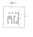
- FIG.1 is an enlargement of a partial plan view of an exemplary pattern layout in a photo-mask.
- Each hatched area constitutes an islandlike pattern of an opaque material such as metallic chromium film formed on a glass substrate 1.
- the pattern 2 for example, has a linear portion of width 'd' of 10 micron or less.
- the images of these patterns are projected on the resist film formed on a silicon wafer in a demagnification factor of xl/5, for instance.
- the actual pattern having the minimum width of 2 micron corresponding to 'd' is formed on the wafer.
- FIG.2 is a conceptual diagram for explaining a method for writing an L-shape pattern in FIG.1 by scanning an intermittent shots of an electron beam.
- Such a complex pattern as the L-shape is usually partitioned into imaginary rectangular patterns, and each rectangular pattern is written by the intermittent shots of an electron beam scanned over each rectangular region in a step-and-repeat mode. That is, in FIG.2, the region occupied by the L-shape pattern is partitioned into the rectangular regions 3 and 4 each comprising a plurality of respective sub-regions 31 or 41.
- Each of the sub-regions 31 or 41 has a size determined by the respective equal-length fractions of the sides of the region 3 or 4, and is subjected to the exposure to a single shot of an electron beam having a cross-section of the same size as that of the sub-region.
- the initial shot of an electron beam is applied to the sub-region 310, which is selected as the origin to define the rectangular region 3, and the successive shots are stepwisely scanned over the region 3 along the arrow-headed lines.
- the scanning of the shots is usually (but not requisite) performed along the longer side of the rectangular region except in the transition to the next scanning line.
- the electron beam is aligned to direct to the sub-region 410, which is selected as the origin to be subjected to the initial shot to the region 4.
- the intermittent shots of the EB begin to be stepwisely scanned over the regions 4 along the arrow-headed lines.
- all sub-regions 31 of the region 3 and the sub-region 41 of the region 4 are subjected to the exposure to the intermittent shots of the electron beam, and the L-shape pattern is generated in the resist film.
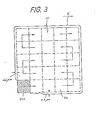
- FIG.3 which illustrates a rectangular pattern 5 (area surrounded by the solid line).
- the pattern 5 has been generated in the manner as described with reference to FIG.2.
- the initial shot of an electron beam was applied to the sub-region 510 (hatched area), and subsequent shots were applied to each sub-region 51 (area defined by the dotted lines) along the arrow-headed lines.
- This spreading has increased stepwisely in the sub-regions corresponding to a few shots (2 or 3 shots) after the initial shot to the sub-region 510 and become constant at the subsequent sub-region, for example, the sub-region 511 - In FIG.3, the shot size of the electron beam, therefore, the designed size of the sub-region 51 is 3 micron square, for example, and the maximum spreading is 0.2 micron at each side. Accordingly, the region 5 (resulting pattern) has an error of 0.4 micron for its designed size.
- the spreading is often observed in the resist film formed on a glass substrate, but not so often in the resist film formed on a silicon wafer. And, as mentioned above, the spreading increases within the two or three sub-regions neighboring the starting sub-region at which exposure to the shots has been initiated, and becomes constant in the subsequent sub-regions. Moreover, the spreading is not observed if sufficient length of pause (blanking period) is provided between the successive shots.
- the EB shot-size- or dosage-controlling involves: I) the necessity of checking the varied shot size or EB dosage together with the accompanied shot size change, and feedback of checking results to the control system; 2) the necessity of analog voltage control according to every steps of the shot size or dosage checking; and is suffered from poor tolerance for the process condition variables relating to the characteristics of the resist film and the substrate; for example, the material, thickness, sensitivity, etc. of the resist film, thermal and electric conductivities of the substrate.
- EB shot of constant size and dosage in order to simplify the process control.
- the spreading can be avoided by providing sufficient length of a pause (blanking time) between every successive EB shots, but there are trade off between the pattern accuracy and the throughput in the pattern generation.
- An embodiment of the present invention can provide an EB exposure method for generating a precision pattern.
- An embodiment of the present invention can provide an EB exposure method for generating a precision pattern without a substantial decrease in the throughput.
- An embodiment - of the present invention can provide an EB exposure method for generating a precision pattern by using an EB of constant size and dosage without a substantial decrease in throughput.
- An embodiment of the present invention provides an EB exposure method for generating an islandlike pattern consisting of a region to be exposed to an EB and surrounded by an unexposed region, a comprising a step of providing sequentially intermittent shots of the EB to a plurality of sub-regions defined by subdividing the islandlike pattern and the step includes subjecting the sub-region at the periphery of the islandlike pattern to a shot with a first pause after a preceding shot and subjecting the sub-region at the inner portion of the islandlike pattern to a shot with a second pause shorter than the first pause after a preceding shot.
- the pattern shown in FIG.3 is generated by the shots of an electron beam having the size of 3 micron square, for example, and operation with the shot duration of 1 ⁇ sec and blanking time of 0.5 psec.
- the spreading of the pattern does not occur if a sufficient blanking time, for example, 4 psec is allowed therebetween.
- the effect of an EB shot to a sub-region is not so strong that it does not affect the resist film in the sub-regions having already been subjected to the precedent exposure.
- the shots to the sub-regions other than that positioned at the periphery can be performed substantially unconcerned to the spreading of the pattern.
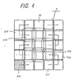
- FIG.4 illustrates a rectangular pattern exposed using the method of the present invention based on the above theory.
- the blanking time between the respective shots to the sub-regions from 510 through 511 to 512 should be long, while the blanking time between the respective shots to the sub-regions 512 and 513 can be relatively short.
- the blanking time between the sub-regions 514 and 515 should be long enough to prevent the sub-region 515 from the residual effect of the shot to the sub-region 514.
- the each exposed area of the sub-regions at the periphery is smaller than that of the sub-regions at the inner portion.
- FIG.5 is an exemplary timing chart of the signal for controlling the blanking time between the EB shots according to the present invention.
- the EB shot is applied to a single sub-region, while each period of the low level of the signal corresponds to the above mentioned blanking time.
- the positioning of the electron beam is performed in the blanking period.
- P 512 and P 513 correspond to the EB shots to the sub-regions 512 and 513, respectively
- P 514 and P 515 correspond to the EB shots to the sub-regions 514 and 515, respectively.
- the exemplary pulse width (high level) is 1 ⁇ sec and the blanking time (low level) between P512 and P 513 is 0.5 ⁇ sec and that between P 514 and P 515 is 4 ⁇ sec.
- FIG.6 is a conceptual block diagram of the EB system used in the present invention.
- the system of FIG.5 is not particularly different from those used in the conventional EB exposure processes, and only the simplified descriptions on its configuration and operations will be given in the following.
- the system shown in FIG.6 comprises the EB column 6, system control 7, sub-control system block 8 and D/A converter block 9.
- the beam shaping means comprising the first square aperture 60, shaping deflector 61, and the second square aperture 62 which trims the electron beam formed by the electron gun 63 and provides an electron beam (EB) having desired shape and size according to the signal supplied by the SHAPE.
- the shaped EB is subject to the deflection for the scanning on the substrate 64 placed on an X-Y stage 65.
- the electrostatic deflection means 66 is responsible for the high speed scanning in the area smaller than few hundreds microns, while the relatively low speed electromagnetic deflection means 67 is used for the EB position registration control ranging from few hundreds microns to few millimeters. Both of the deflections are controlled by the FIELD DEFLECTOR.
- the blanker 68 deflects the shaped beam to be absorbed by the final aperture 69 according to the signal as shown in FIG.4 under the control of the BLANK, thus the intermittent EB shots having predetermined variable blanking times are provided.
- the system control 7 always checks the coordinate data of each sub-region to be subjected to the next EB shot, and commands the BLANK in the sub-system control 8 to add a predetermined increment of time to the normal blanking time (0.5 psec, for example), if it judges that the subject coordinate data includes at least one of the coordinate components defining the contour of the pattern to be generated.
- the 1 ⁇ sec of EB shot to the precedent sub-region and the following blanking time of at least 0.5 ⁇ sec is enough to afford checking the coordinate data of the subsequent sub-region. Accordingly, increase in the time required for the pattern generation arises only from the increment in the blanking time.
- the present invention enable to decrease the pattern generation time by the reduction in the blanking times prior to the shots to the sub-regions other than those at the periphery of the pattern compared with the prior art precision pattern generation method wherein the blanking time is set long equally for every shots, such as 4 psec.
- the complicated pattern is partitioned into plural rectangular patterns.
- the region occupied by the pattern is partitioned into two rectangular regions 3 and 4.
- the EB shots to the sub-regions 31 and 41 lying close to the boundary of the rectangular regions 3 and 4 can be indifferent to the aforesaid spreading due to the residual effect. Therefore, the reduction in the time required for the pattern generation can be decreased further.
- the point of the present invention is that the blanking time prior to the EB shot for a sub-region at the periphery of an islandlike pattern is short whereas the blanking time prior to the EB shot for a sub-region at the inner portion of the pattern, wherein the islandlike pattern means an exposed region surrounded by an unexposed region.
Landscapes
- Chemical & Material Sciences (AREA)
- Engineering & Computer Science (AREA)
- Nanotechnology (AREA)
- Analytical Chemistry (AREA)
- Physics & Mathematics (AREA)
- Crystallography & Structural Chemistry (AREA)
- Theoretical Computer Science (AREA)
- Condensed Matter Physics & Semiconductors (AREA)
- General Physics & Mathematics (AREA)
- Manufacturing & Machinery (AREA)
- Mathematical Physics (AREA)
- Electron Beam Exposure (AREA)
- Exposure And Positioning Against Photoresist Photosensitive Materials (AREA)
Applications Claiming Priority (2)
| Application Number | Priority Date | Filing Date | Title |
|---|---|---|---|
| JP37934/84 | 1984-02-29 | ||
| JP59037934A JPS60196941A (ja) | 1984-02-29 | 1984-02-29 | 電子線露光方法 |
Publications (3)
| Publication Number | Publication Date |
|---|---|
| EP0153864A2 true EP0153864A2 (de) | 1985-09-04 |
| EP0153864A3 EP0153864A3 (en) | 1987-04-08 |
| EP0153864B1 EP0153864B1 (de) | 1989-08-09 |
Family
ID=12511384
Family Applications (1)
| Application Number | Title | Priority Date | Filing Date |
|---|---|---|---|
| EP85301356A Expired EP0153864B1 (de) | 1984-02-29 | 1985-02-28 | Elektronenstrahl-Belichtungsverfahren |
Country Status (5)
| Country | Link |
|---|---|
| US (1) | US4625121A (de) |
| EP (1) | EP0153864B1 (de) |
| JP (1) | JPS60196941A (de) |
| KR (1) | KR900001715B1 (de) |
| DE (1) | DE3572254D1 (de) |
Families Citing this family (6)
| Publication number | Priority date | Publication date | Assignee | Title |
|---|---|---|---|---|
| JPS6229135A (ja) * | 1985-07-29 | 1987-02-07 | Advantest Corp | 荷電粒子ビ−ム露光方法及びこの方法を用いた荷電粒子ビ−ム露光装置 |
| US4818885A (en) * | 1987-06-30 | 1989-04-04 | International Business Machines Corporation | Electron beam writing method and system using large range deflection in combination with a continuously moving table |
| JP2614884B2 (ja) * | 1988-02-04 | 1997-05-28 | 富士通株式会社 | 電子ビーム露光方法及びその装置 |
| KR950002578B1 (ko) * | 1991-03-13 | 1995-03-23 | 후지쓰 가부시끼가이샤 | 전자빔 노광방법 |
| JP2880350B2 (ja) * | 1992-06-01 | 1999-04-05 | 株式会社日立製作所 | 電子線描画装置、及び、電子線描画方法 |
| JP2004040010A (ja) * | 2002-07-08 | 2004-02-05 | Renesas Technology Corp | パターン描画方法 |
Family Cites Families (9)
| Publication number | Priority date | Publication date | Assignee | Title |
|---|---|---|---|---|
| JPS5425675A (en) * | 1977-07-28 | 1979-02-26 | Nec Corp | Electron beam exposure unit |
| JPS5710233A (en) * | 1980-06-23 | 1982-01-19 | Jeol Ltd | Electron beam exposing method |
| DE3169257D1 (en) * | 1980-11-28 | 1985-04-18 | Ibm | Electron beam system and method |
| JPS57112020A (en) * | 1980-12-29 | 1982-07-12 | Fujitsu Ltd | Exposure of electron beam |
| JPS57162337A (en) * | 1981-03-31 | 1982-10-06 | Nec Corp | Charged particle beam type lithographic method |
| JPS5828832A (ja) * | 1981-08-12 | 1983-02-19 | Nec Corp | 電子ビ−ム露光方法 |
| US4433384A (en) * | 1981-10-05 | 1984-02-21 | Varian Associates, Inc. | Pattern data handling system for an electron beam exposure system |
| US4482810A (en) * | 1982-09-30 | 1984-11-13 | Storage Technology Partners | Electron beam exposure system |
| US4477729A (en) * | 1982-10-01 | 1984-10-16 | International Business Machines Corporation | Continuously writing electron beam stitched pattern exposure system |
-
1984
- 1984-02-29 JP JP59037934A patent/JPS60196941A/ja active Pending
-
1985
- 1985-02-22 US US06/704,515 patent/US4625121A/en not_active Expired - Lifetime
- 1985-02-26 KR KR1019850001201A patent/KR900001715B1/ko not_active Expired
- 1985-02-28 DE DE8585301356T patent/DE3572254D1/de not_active Expired
- 1985-02-28 EP EP85301356A patent/EP0153864B1/de not_active Expired
Also Published As
| Publication number | Publication date |
|---|---|
| KR900001715B1 (ko) | 1990-03-19 |
| JPS60196941A (ja) | 1985-10-05 |
| EP0153864B1 (de) | 1989-08-09 |
| US4625121A (en) | 1986-11-25 |
| KR850006647A (ko) | 1985-10-14 |
| EP0153864A3 (en) | 1987-04-08 |
| DE3572254D1 (en) | 1989-09-14 |
Similar Documents
| Publication | Publication Date | Title |
|---|---|---|
| JP2680074B2 (ja) | 荷電粒子ビーム露光を用いた半導体装置の製造方法 | |
| US6433348B1 (en) | Lithography using multiple pass raster-shaped beam | |
| KR100581478B1 (ko) | 마이크로컬럼 어레이를 이용한 반도체 다이의 직기입 방법및 장치 | |
| KR20080104981A (ko) | 묘화 방법 및 하전 입자 빔 묘화 장치 | |
| JPH06132203A (ja) | 荷電粒子ビーム露光方法 | |
| JP3601630B2 (ja) | 荷電粒子線転写方法 | |
| JPH0468768B2 (de) | ||
| JP3295855B2 (ja) | 荷電粒子ビーム露光方法 | |
| US4163155A (en) | Defining a low-density pattern in a photoresist with an electron beam exposure system | |
| EP0153864B1 (de) | Elektronenstrahl-Belichtungsverfahren | |
| JP2647000B2 (ja) | 電子ビームの露光方法 | |
| KR100379290B1 (ko) | 전자빔 노광용 마스크와 이를 이용한 반도체 장치 제조 방법 | |
| JP3206448B2 (ja) | 電子ビーム描画装置 | |
| CN1271461A (zh) | 通过电子束写图形的方法和设备 | |
| US6087048A (en) | Method of producing block mask for electron-beam lithography apparatuses | |
| US6271531B1 (en) | Charged beam drawing apparatus and method thereof | |
| JP2005302868A (ja) | 電子ビーム描画方法および装置 | |
| JP2871617B2 (ja) | 電子線露光方法 | |
| JPS60126826A (ja) | 電子ビ−ム露光装置 | |
| JP2898726B2 (ja) | 荷電粒子ビーム露光方法 | |
| JPH11237728A (ja) | 描画方法及び描画装置 | |
| JPS62156816A (ja) | パタ−ン描画方法 | |
| JPH05326356A (ja) | レーザ描画装置および方法 | |
| JPH02278711A (ja) | 微細パターンの形成方法 | |
| JPS6230321A (ja) | 電子ビ−ム露光方法および電子ビ−ム露光装置 |
Legal Events
| Date | Code | Title | Description |
|---|---|---|---|
| PUAI | Public reference made under article 153(3) epc to a published international application that has entered the european phase |
Free format text: ORIGINAL CODE: 0009012 |
|
| AK | Designated contracting states |
Designated state(s): DE FR GB |
|
| PUAL | Search report despatched |
Free format text: ORIGINAL CODE: 0009013 |
|
| AK | Designated contracting states |
Kind code of ref document: A3 Designated state(s): DE FR GB |
|
| 17P | Request for examination filed |
Effective date: 19870512 |
|
| 17Q | First examination report despatched |
Effective date: 19880414 |
|
| GRAA | (expected) grant |
Free format text: ORIGINAL CODE: 0009210 |
|
| AK | Designated contracting states |
Kind code of ref document: B1 Designated state(s): DE FR GB |
|
| REF | Corresponds to: |
Ref document number: 3572254 Country of ref document: DE Date of ref document: 19890914 |
|
| ET | Fr: translation filed | ||
| PLBE | No opposition filed within time limit |
Free format text: ORIGINAL CODE: 0009261 |
|
| STAA | Information on the status of an ep patent application or granted ep patent |
Free format text: STATUS: NO OPPOSITION FILED WITHIN TIME LIMIT |
|
| 26N | No opposition filed | ||
| PGFP | Annual fee paid to national office [announced via postgrant information from national office to epo] |
Ref country code: FR Payment date: 19940210 Year of fee payment: 10 |
|
| PGFP | Annual fee paid to national office [announced via postgrant information from national office to epo] |
Ref country code: GB Payment date: 19940218 Year of fee payment: 10 |
|
| PGFP | Annual fee paid to national office [announced via postgrant information from national office to epo] |
Ref country code: DE Payment date: 19940224 Year of fee payment: 10 |
|
| PG25 | Lapsed in a contracting state [announced via postgrant information from national office to epo] |
Ref country code: GB Effective date: 19950228 |
|
| GBPC | Gb: european patent ceased through non-payment of renewal fee |
Effective date: 19950228 |
|
| PG25 | Lapsed in a contracting state [announced via postgrant information from national office to epo] |
Ref country code: FR Effective date: 19951031 |
|
| PG25 | Lapsed in a contracting state [announced via postgrant information from national office to epo] |
Ref country code: DE Effective date: 19951101 |
|
| REG | Reference to a national code |
Ref country code: FR Ref legal event code: ST |