EP0153983A1 - Vorrichtung zum Stapeln von Signaturen - Google Patents
Vorrichtung zum Stapeln von Signaturen Download PDFInfo
- Publication number
- EP0153983A1 EP0153983A1 EP84109139A EP84109139A EP0153983A1 EP 0153983 A1 EP0153983 A1 EP 0153983A1 EP 84109139 A EP84109139 A EP 84109139A EP 84109139 A EP84109139 A EP 84109139A EP 0153983 A1 EP0153983 A1 EP 0153983A1
- Authority
- EP
- European Patent Office
- Prior art keywords
- signatures
- platform
- edge portion
- retractable
- group
- Prior art date
- Legal status (The legal status is an assumption and is not a legal conclusion. Google has not performed a legal analysis and makes no representation as to the accuracy of the status listed.)
- Granted
Links
- 230000001154 acute effect Effects 0.000 claims description 4
- 230000006835 compression Effects 0.000 description 25
- 238000007906 compression Methods 0.000 description 25
- 230000000712 assembly Effects 0.000 description 5
- 238000000429 assembly Methods 0.000 description 5
- 238000010276 construction Methods 0.000 description 3
- 230000001105 regulatory effect Effects 0.000 description 2
- 238000009825 accumulation Methods 0.000 description 1
- 230000015572 biosynthetic process Effects 0.000 description 1
- 230000007423 decrease Effects 0.000 description 1
- 238000000034 method Methods 0.000 description 1
Images

Classifications
-
- B—PERFORMING OPERATIONS; TRANSPORTING
- B65—CONVEYING; PACKING; STORING; HANDLING THIN OR FILAMENTARY MATERIAL
- B65H—HANDLING THIN OR FILAMENTARY MATERIAL, e.g. SHEETS, WEBS, CABLES
- B65H31/00—Pile receivers
- B65H31/30—Arrangements for removing completed piles
- B65H31/3009—Arrangements for removing completed piles by dropping, e.g. removing the pile support from under the pile
- B65H31/3018—Arrangements for removing completed piles by dropping, e.g. removing the pile support from under the pile from opposite part-support elements, e.g. operated simultaneously
-
- B—PERFORMING OPERATIONS; TRANSPORTING
- B65—CONVEYING; PACKING; STORING; HANDLING THIN OR FILAMENTARY MATERIAL
- B65H—HANDLING THIN OR FILAMENTARY MATERIAL, e.g. SHEETS, WEBS, CABLES
- B65H31/00—Pile receivers
- B65H31/30—Arrangements for removing completed piles
- B65H31/3081—Arrangements for removing completed piles by acting on edge of the pile for moving it along a surface, e.g. by pushing
-
- B—PERFORMING OPERATIONS; TRANSPORTING
- B65—CONVEYING; PACKING; STORING; HANDLING THIN OR FILAMENTARY MATERIAL
- B65H—HANDLING THIN OR FILAMENTARY MATERIAL, e.g. SHEETS, WEBS, CABLES
- B65H31/00—Pile receivers
- B65H31/32—Auxiliary devices for receiving articles during removal of a completed pile
-
- B—PERFORMING OPERATIONS; TRANSPORTING
- B65—CONVEYING; PACKING; STORING; HANDLING THIN OR FILAMENTARY MATERIAL
- B65H—HANDLING THIN OR FILAMENTARY MATERIAL, e.g. SHEETS, WEBS, CABLES
- B65H33/00—Forming counted batches in delivery pile or stream of articles
- B65H33/06—Forming counted batches in delivery pile or stream of articles by displacing articles to define batches
-
- B—PERFORMING OPERATIONS; TRANSPORTING
- B65—CONVEYING; PACKING; STORING; HANDLING THIN OR FILAMENTARY MATERIAL
- B65H—HANDLING THIN OR FILAMENTARY MATERIAL, e.g. SHEETS, WEBS, CABLES
- B65H2301/00—Handling processes for sheets or webs
- B65H2301/40—Type of handling process
- B65H2301/42—Piling, depiling, handling piles
- B65H2301/421—Forming a pile
- B65H2301/4211—Forming a pile of articles alternatively overturned, or swivelled from a certain angle
- B65H2301/42112—Forming a pile of articles alternatively overturned, or swivelled from a certain angle swivelled from 180°
-
- B—PERFORMING OPERATIONS; TRANSPORTING
- B65—CONVEYING; PACKING; STORING; HANDLING THIN OR FILAMENTARY MATERIAL
- B65H—HANDLING THIN OR FILAMENTARY MATERIAL, e.g. SHEETS, WEBS, CABLES
- B65H2301/00—Handling processes for sheets or webs
- B65H2301/40—Type of handling process
- B65H2301/42—Piling, depiling, handling piles
- B65H2301/422—Handling piles, sets or stacks of articles
- B65H2301/4223—Pressing piles
-
- B—PERFORMING OPERATIONS; TRANSPORTING
- B65—CONVEYING; PACKING; STORING; HANDLING THIN OR FILAMENTARY MATERIAL
- B65H—HANDLING THIN OR FILAMENTARY MATERIAL, e.g. SHEETS, WEBS, CABLES
- B65H2301/00—Handling processes for sheets or webs
- B65H2301/40—Type of handling process
- B65H2301/42—Piling, depiling, handling piles
- B65H2301/422—Handling piles, sets or stacks of articles
- B65H2301/4226—Delivering, advancing piles
- B65H2301/42261—Delivering, advancing piles by dropping
- B65H2301/422615—Delivering, advancing piles by dropping from opposite part-support elements, e.g. operated simultaneously
-
- B—PERFORMING OPERATIONS; TRANSPORTING
- B65—CONVEYING; PACKING; STORING; HANDLING THIN OR FILAMENTARY MATERIAL
- B65H—HANDLING THIN OR FILAMENTARY MATERIAL, e.g. SHEETS, WEBS, CABLES
- B65H2301/00—Handling processes for sheets or webs
- B65H2301/40—Type of handling process
- B65H2301/42—Piling, depiling, handling piles
- B65H2301/422—Handling piles, sets or stacks of articles
- B65H2301/4226—Delivering, advancing piles
- B65H2301/42266—Delivering, advancing piles by acting on edge of the pile for moving it along a surface, e.g. pushing
-
- B—PERFORMING OPERATIONS; TRANSPORTING
- B65—CONVEYING; PACKING; STORING; HANDLING THIN OR FILAMENTARY MATERIAL
- B65H—HANDLING THIN OR FILAMENTARY MATERIAL, e.g. SHEETS, WEBS, CABLES
- B65H2402/00—Constructional details of the handling apparatus
- B65H2402/30—Supports; Subassemblies; Mountings thereof
- B65H2402/35—Supports; Subassemblies; Mountings thereof rotating around an axis
- B65H2402/351—Turntables
-
- Y—GENERAL TAGGING OF NEW TECHNOLOGICAL DEVELOPMENTS; GENERAL TAGGING OF CROSS-SECTIONAL TECHNOLOGIES SPANNING OVER SEVERAL SECTIONS OF THE IPC; TECHNICAL SUBJECTS COVERED BY FORMER USPC CROSS-REFERENCE ART COLLECTIONS [XRACs] AND DIGESTS
- Y10—TECHNICAL SUBJECTS COVERED BY FORMER USPC
- Y10S—TECHNICAL SUBJECTS COVERED BY FORMER USPC CROSS-REFERENCE ART COLLECTIONS [XRACs] AND DIGESTS
- Y10S414/00—Material or article handling
- Y10S414/10—Associated with forming or dispersing groups of intersupporting articles, e.g. stacking patterns
- Y10S414/12—Associated with forming or dispersing groups of intersupporting articles, e.g. stacking patterns including means pressing against top or end of group
Definitions
- the present invention relates to a new and improved signature handling apparatus and more specifically to a signature handling apparatus for use in stacking signatures having one edge which is thicker than other edges of the signatures.
- a known apparatus for stacking signatures having one edge thicker than other edges is disclosed in U.S. Patent No. 4,183,704.
- the apparatus disclosed in this patent accumulates the signatures on a temporary holding platform formed by a plurality of tines connected with rotatable shafts. After a predetermined number of signatures, corresponding to a portion of a stack of signatures, has been collected on the temporary holding apparatus, the signatures are dropped onto a turntable.
- the turntable is rotated through 180° after receipt of each portion of the stack of signatures from the temporary holding platform. This results in the relatively thick edges of the signatures in one portion of the stack being offset from the relatively thick edges of signatures in another portion of the stack. Since the relatively thick edges of the signatures are offset, the accumulation of the relatively thick edges along one side of the stack and a resulting upward extension of that side of the stack is avoided.
- the present invention relates to a new and improved signature handling apparatus for use in stacking signatures having one edge which is thicker than other edges of the signatures.
- the relatively thick edges of the signatures are compensated for by (1) compressing the relatively thick edges to flatten the signatures and (2) offsetting the relatively thick edges in successive layers in a stack of signatures.
- the signature handling apparatus includes a platform which receives the signatures in an initial spatial orientation.
- the platform is rotated about a vertical axis to offset a first group of signatures on the platform from the initial spatial orientation. This results in the signatures which are subsequently received on the platform in the initial spatial orientation having relatively thick edges which are offset from the relatively thick edges of the signatures which had previously been deposited on the platform.
- Each group of signatures on the platform is compressed before the succeeding group of signatures is deposited on the platform.
- a retractable apparatus is extended over the platform.
- the platform is then raised to press the signatures on the platform against the retractable apparatus which is extending over the platform. This results in a flattening of the relatively thick edges of the signatures which are on the platform.
- a signature handling apparatus 10 constructed in accordance with the present invention is illustrated schematically in Figs. 1 and 2.
- the signature handling apparatus 10 is operable to produce generally rectangular and relatively stable stacks of signatures which can be readily handled even though the signatures have one edge portion which is thicker than the other edge portions. Signatures which are folded along one edge portion tend to expand at that edge portion and be thicker along the folded edge portion than at other edge portions of the signatures. If these signatures are stacked without compensating for the relatively thick folded edge portion . of the signatures, one side of the stack tends to project a substantial distance upwardly relative to the other sides of the stack with a resulting instability which increases the difficulty of handling the stack of signatures.
- the signature handling apparatus 10 compensates for the relatively thick folded edge portion of the signatures by flattening the folded edge portions of the signatures. In addition, the apparatus 10 compensates for the relatively thick edge portion of the signatures by offsetting successive layers in a pile of signatures. Although the relatively thick edge portion of the signatures is described herein as.resulting from folding the signatures, it should be understood that the relatively thick edge portion of the signatures could be due to other causes, such as stapling, binding, or the provision of narrow inserts in the signatures.
- the signature handling apparatus 10 includes an infeed conveyor 14 along which signatures 16 are fed in a spaced apart relationship with their relatively thick folded edge portions 18 leading.
- the signatures are fed from the infeed conveyor 14 to a signature stacking apparatus 20.
- a pusher assembly 22 (Fig. 1) is operable to sequentially push stacks of signatures 24 onto a delivery conveyor 26.
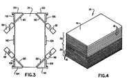
- Each stack 24 (see Fig. 4) of signatures includes a plurality of layers or pile sections, such as an upper layer or pile section 32 and a lower layer or pile section 34.
- Each of the signatures 16 is fed to the signature stacking apparatus 20 with a relatively thick folded edge portion 18 of the signature leading, in the manner illustrated schematically in Fig. 2.
- the flattened folded edge portions 18 of the signatures in one layer or pile portion of the stack 24 is-offset from the folded edge portion 18 of the signatures in an adjacent layer.
- the folded edge portions 18 of the upper layer 32 in the stack 24 of signatures face toward the right, as viewed in Fig. 4.
- the folded edge portions 18 of the lower layer 34 in the stack 24 of signatures face toward the left. This results in a generally rectangular stack 24 of signatures which is relatively stable and can be easily handled.
- the folded edge portions 18 in the upper and lower layers 32 and 34 of signatures in the stack 24 of signatures have been shown (Fig. 4) as being offset from each other by 180°, it is contemplated that the folded edge portions could be offset by 90°. Of course, if this was done, the stack 24 of signatures would contain at least four layers in order to obtain the desired rectangular configuration.
- Signatures are fed to the signature stacking apparatus 20 by the infeed conveyor 14. As the signatures 16 are sequentially fed toward the stacking apparatus 20, a light source 38 cooperates with a light responsive sensor 40 to provide signals which enable a control apparatus 42 to count the number of signatures fed to the stacking apparatus 20 in a known manner.
- the signatures are fed to the stacking apparatus 20, they are accumulated in a temporary holding assembly 46 (Fig. 2) until a predetermined number of signatures have been accumulated.
- a layer or pile portion is dropped from the holding apparatus 46 onto a platform or table 50 in a stack compression and compensating apparatus 52.
- the platform 50 While a next succeeding layer or pile portion of signatures is being accumulated in the temporary signature holding apparatus 46, the platform 50 is lowered. The platform is lowered until the top of a group of signatures on the platform 50 is below the level of a retractable apparatus 56. As the platform 50 is being lowered, compression rods 60 are retracted in piston and cylinder assemblies 62. Shortly after the upper edge of the lower layer of signatures has moved downwardly past the level of compression rods 60, the motors 62 are operated to move the rods to their extended positions shown in Fig. 2.
- the layer 34 of signatures on the platform 50 is lowered, the layer of signatures moves past a light source 66 and light sensitive element 68. When this happens, a signal is transmitted to the control apparatus 42. After a short time delay, during which the upper edge of the layer 34 of signatures moves downwardly below the compression rods 60, the motors 62 are operated to extend the compression rods.
- the platform 50 is then raised to press the pile portion or layer 34 against the extended compression rods 60. This compresses the layer 34 and flattens the relatively thick folded edge portions 18 of the signatures 16. Flattening the edge portions of the signatures decreases the amount by which the edge portion of the layer 34 containing the thick edges of the signatures extends upwardly above the opposite edge portion of the layer.
- the layer 34 and platform 50 are rotated so that the folded edge portions of the signatures on the platform are offset from the folded edge portions of a next succeeding layer of signatures being accumulated in the signature holding assembly 46.
- a drive assembly 72 is operated to rotate the platform 50.
- a stack positioning assembly 74 rotates with the platform 50 about a vertical central axis of the stack compression and compensation apparatus 52.
- Operation of the drive assembly 72 rotates the layer 34 through 180° from the initial position shown in Fig. 2. This results in the relatively thick folded edge portions 18 of the signatures 16 in the layer 34 being disposed immediately beneath the relatively thin open edge portions of the signatures being accumulated in the temporary signature holding assembly 46. Although it is preferred to rotate the layer 34 through 180° from the initial position shown in Fig. 2 by operation of the drive assembly 72, it is contemplated that the drive assembly 72 could be operated to rotate the layer 34 through 90° for each layer that is accumulated in the stack compression and compensation apparatus 52.
- the next succeeding layer or pile portion 32 When the next succeeding layer or pile portion 32 has been accumulated in the temporary signature holding assembly 46, the next succeeding layer 32 is dropped onto the preceding layer 34 on the platform 50. As the layer 32 drops downwardly, it moves between the light source 66 and photocell 68. This signals the control apparatus 42 to operate the motors 62 and retract the compression rods 60. After a slight time delay, the platform 50 is lowered.
- the control apparatus 42 to interrupt the downward movement of the platform 50 after sufficient time has passed to enable the upper edge of the layer 32 to move below compression rods 60.
- the motors 62 are then operated to extend compression rods 60.
- the platform 50 is then raised to press the upper layer 32 against the compression rods 60 and flatten the relatively thick folded edges of the signatures in the layer 32.
- the platform 50 is lowered.
- the pusher assembly 22 (see Fig. 1) is then operated to push the stack out of the signature stacking apparatus 20 onto the delivery conveyor 26.
- the stack 24 will be generally rectangular in configuration and will be comparatively stable. This is because the relatively thick folded edge portions 18 will have been compensated for by flattening the signatures against the compression rods 60 and by offsetting the layers in the stack.
- the temporary signature holding assembly 46 receives each of the signatures 16 in turn from the infeed conveyor 14. As the signatures are fed by the conveyor 14 into the temporary signature holding assembly 46, the leading folded edge portion 18 of each of the signatures impacts against a vertical alignment bar 78 (see Fig. 2). The signatures then fall downwardly onto a temporary platform 82 disposed between alignment bars 78 and 84.
- the temporary platform 82 is formed by a plurality of parallel fingers or tines 86 and 88 which extend inwardly from rotatable shafts 90 and 92.
- the shafts 90 and 92 are rapidly rotated through 360° to allow the layer of signatures to drop downward toward the platform 50.
- the shaft 90 is rotated in a clockwise direction (as viewed in Fig. 2) and the shaft 92 is rotated in a counterclockwise direction.
- the speed of rotation of the shafts 90 and 92 is such that the fingers or tines 86 and 88 are back in the position shown in Fig. 2 before the signature which is to form the bottom of the next succeeding layer has dropped downwardly in the temporary signature holding assembly 46.
- the temporary signature holding assembly 46 has the same construction as is described in U.S. Patent No. 4,183,704. Therefore, the construction of the temporary signature holding assembly 46 will not be further described herein in order to avoid prolixity of description. However, it should be understood that temporary signature holding assemblies of a different construction could be used if desired.
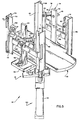
- the stack compression and compensation apparatus 52 (see Fig. 5) includes the stack positioning assembly 74.
- the stack positioning assembly 74 positions the layers 32 and 34 (Figs. 2 and,4) relative to the platform 50 as they drop from the temporary holding assembly 46.
- the stack positioning assembly 74 includes a plurality of upright positioning bars 102, 104, 106, 108, 110 and 112 which engage the edge portions of the signatures to position them transversely to the platform 50.
- a plurality of gates are connected with the positioning bars to locate the signatures along the platform.
- a gate 114 is pivotally connected with the positioning bar 102 by spring loaded hinge connections 118.
- Gates 122, 124 and 1.26 are pivotally connected with the positioning bars 106, 108 and 112 in a similar manner.
- the gates 114, 122, 124 and 126 are spring pressed against the sides of the signatures disposed on the platform 50 to maintain the signatures in position along the platform.
- the platform 50 and stack positioning assembly 74 are rotated together through 180° by the drive assembly 72 to offset layers of signatures relative to each other. Therefore, the pusher assembly 22 (see Fig. 1) may push a signature out through the gates 122 and 126 (see Fig. 5) or out through the gates l14 and 124, depending upon the orientation of the platform 50 and stack positioning assembly 74 relative to the pusher assembly 22. Since the gates 114, 122, 124 and 126 are all hinged for outward pivotal movement, the stack can be pushed from either end of the platform 50. Of course the pusher assembly 22 is small enough to extend through the space between the gates.
- the signature positioning assembly 74 includes a base plate 132 on which the positioning bars 102-112 are supported.
- the center positioning bars 104 and 110 are connected with the base plate 132 by a pair of releasable clamp assemblies, only the clamp assembly 136 being illustrated in the drawings.
- the vertical end positioning bars 102, 106, 108 and 112 are connected with the center positioning bars 104 and 110 by horizontal cross members 140, 142, 144 and 146. Therefore, upon release of the clamp assemblies 136 for the center positioning bars 104 and 110, the locations of all of the positioning bars can be adjusted relative to the base plate 132 to accommodate stacks of different widths.
- a pair of clamp assemblies 148 are releasable to enable the positions of the bars 102, 106, 108 and l12 and gates 114, 122, 124 and 126 to be adjusted to accommodate stacks of different lengths.
- the platform drive assembly 72 rotates the platform 50 and stack positioning assembly 74 about their coincident vertical central axes while signatures on the platform are pressed against the compression rods 60.
- the drive assembly 72 is operable to rotate the platform 50 and stack positioning assembly 74 back and forth along a 180° arc of movement. Any known drive system could be utilized to rotate the platform 50 and stack positioning assembly 74. However, it is preferred to use the drive assembly disclosed in U.S. Patent No. 4,140,234. Operation of the pneumatic piston and cylinder type motor in the drive assembly 72 is regulated by the control apparatus 42 in a known manner.
- the platform 50 is raised and lowered by the pneumatic motor 150.
- the motor 150 includes a cylinder 154 which is fixedly connected with the base plate 132 of the stack positioning assembly 74.
- the motor 150 includes a piston 158 (see Fig. 2) which is connected with the platform 50 by a cylindrical piston rod 160.
- the control apparatus 42 directs air under pressure into the head end of the cylinder 154 and exhausts the rod end of the cylinder. Similarly, when the platform 50 is to be lowered, the head end of the cylinder 154 is exhausted to the atmosphere and air pressure is supplied to the rod end of the cylinder. The force with which the signatures are pressed against the compression rods 60 is controlled by regulating the air pressure applied against the head end of the piston 158.
- the platform 50 and cylindrical piston rod 160 are held against rotation relative to the cylinder 154 and base 132 (see Fig. 5) by engagement of the edges of the platform 50 with the upright positioning bars 102-112.
- anti-friction surfaces formed by threaded fasteners of a polymeric material, on the sides of the platform 50 rub against the inner side surfaces of the positioning bars 102-112.
- the platform 50 may be desirable to hold the platform 50 against rotation by holding the piston rod 160 against rotation. This can be done by forming a section of the piston rod with a polygonal cross sectional configuration and sliding the piston rod in a similarly shaped sleeve. Of course, a slot and key-way arrangement could be used if desired. By holding the piston rod 160 and platform 50 against rotation in this manner, the positioning bars 102-112 can be moved away from the side edges of the platform to enable the platform to accommodate stacks having a slightly greater area than the top of the platform.
- the retractable apparatus 56 includes pneumatic piston and cylinder type motors 62 which are mounted on the cross members 140-146 on mounting blocks 166, 168, 170 and 172 (see Fig. 5).
- the mounting blocks 166-172 support the motors 56 with their longitudinal central axes skewed at acute angles relative to the edges of the platform 50.
- the central axes of the compression rod 60 are skewed at acute angles relative to the edge portions of the signatures.
- additional compression rods and motors could be used if desired.
- the motor 150 is effective to continuously press the signatures on the platform 50 upwardly against the compression rods 60 from a time shortly after the signatures have been lowered beneath the light source 66 and photocell 68 until a next succeeding layer of signatures drops downwardly through the space between the light source and photocell.
- the present invention relates to a new and improved signature handling apparatus 10 for use in stacking signatures 16 having one edge portion 18 which is thicker than other edge portions of the signature.
- the relatively thick edge portions 18 of the signatures are compensated for by (1) compressing the relatively thick edge portions to flatten the signatures and (2) offsetting the relatively thick edges portions of the signatures in successive layers 32 and 34 in a stack 24 of signatures.
- the signature handling apparatus 10 includes a platform 50 which receives the signatures 16 with the relatively thick edge portion 18 of each signature in an initial spatial orientation (Fig. 2).
- the platform 50 is rotated about a vertical axis to offset a first group of signatures 34 on the platform from the initial spatial orientation. This results in the signatures 16 in the group of signatures 32 being subsequently received on the platform 50 in the initial spatial orientation having relatively thick edge portions 18 offset from the relatively thick edge portions of the groups 34 of signatures which had previously been deposited on the platform 50.
- Each group of signatures on the platform 50 is compressed before the succeeding group of signatures is deposited on the platform.
- a retractable apparatus 56 is extended over the platform.
- the platform 50 is then raised to press the signatures on the platform against the retractable apparatus 56 which is extending over the platform. This results in a flattening of the relatively thick edge portions 18 of the signatures which are disposed on the platform 50. While the signatures are being pressed against the retractable apparatus 56, the platform 50 and signatures are rotated by the drive assembly 72.
Landscapes
- Engineering & Computer Science (AREA)
- Mechanical Engineering (AREA)
- Pile Receivers (AREA)
- Forming Counted Batches (AREA)
Applications Claiming Priority (2)
| Application Number | Priority Date | Filing Date | Title |
|---|---|---|---|
| US06/572,581 US4547112A (en) | 1984-01-20 | 1984-01-20 | Signature handling apparatus |
| US572581 | 1984-01-20 |
Publications (2)
| Publication Number | Publication Date |
|---|---|
| EP0153983A1 true EP0153983A1 (de) | 1985-09-11 |
| EP0153983B1 EP0153983B1 (de) | 1988-06-15 |
Family
ID=24288475
Family Applications (1)
| Application Number | Title | Priority Date | Filing Date |
|---|---|---|---|
| EP84109139A Expired EP0153983B1 (de) | 1984-01-20 | 1984-08-01 | Vorrichtung zum Stapeln von Signaturen |
Country Status (3)
| Country | Link |
|---|---|
| US (1) | US4547112A (de) |
| EP (1) | EP0153983B1 (de) |
| DE (1) | DE3472094D1 (de) |
Cited By (18)
| Publication number | Priority date | Publication date | Assignee | Title |
|---|---|---|---|---|
| EP0167704A3 (en) * | 1984-07-13 | 1986-04-23 | Nichiro Kogyo Company, Ltd. | An apparatus for stacking small bundles of signatures |
| EP0279333A3 (en) * | 1987-02-18 | 1989-06-28 | Sesto Palamides | Method and device for packaging printing products method and device for packaging printing products |
| EP0315104A3 (en) * | 1987-11-06 | 1990-06-13 | Systel International S.P.A. | Stacking and compacting device for sheets, particularly photographic prints |
| EP0408952A1 (de) * | 1989-07-20 | 1991-01-23 | WindmÀ¶ller & Hölscher | Vorrichtung zum Bilden von Stapeln aus aufeinanderfolgend geförderten flachen Werkstücken |
| EP0477763A1 (de) * | 1990-09-27 | 1992-04-01 | Gämmerler, Hagen | Verfahren und Vorrichtung zum Ablegen und Transportieren von Flächengebilden |
| FR2693179A1 (fr) * | 1992-07-03 | 1994-01-07 | Martin Sa | Organe de retenue de feuilles pour un magasin d'empilage. |
| EP0640547A1 (de) * | 1993-08-25 | 1995-03-01 | Hagen Gämmerler | Drehbare Stapelkammer in einem Kreuzleger für Druckprodukte |
| US6692208B1 (en) | 2000-03-07 | 2004-02-17 | Watkiss Automation Limited | Method of and apparatus for producing booklets |
| EP1593633A1 (de) * | 2004-05-05 | 2005-11-09 | Müller Martini Holding AG | Vorrichtung zum Bilden von Stapeln aus Druckprodukten |
| US6966743B2 (en) | 2002-05-17 | 2005-11-22 | Müller Martini Holding AG | Device for pushing a stack of printed products from a table |
| WO2006094343A1 (en) * | 2005-03-07 | 2006-09-14 | Confoil Pty Ltd | Apparatus and method for stacking containers during a manufacturing operation |
| US7192028B2 (en) | 2001-04-23 | 2007-03-20 | Grapha-Holding Ag | Device for processing printed products supplied to a stacking device |
| US7325799B2 (en) | 2003-05-21 | 2008-02-05 | Watkiss Automation Limited | Method and apparatus for booklet production |
| FR2955317A1 (fr) * | 2010-01-15 | 2011-07-22 | Recmi Ind | Procede et un dispositif d'empilage vertical de documents |
| FR2975980A1 (fr) * | 2011-06-06 | 2012-12-07 | Recmi Ind | Procede et un dispositif d'empilage vertical de documents |
| US8329605B2 (en) | 2007-06-15 | 2012-12-11 | Saint-Gobain Centre De Recherches Et D'etudes Europeen | Sintered product with a cubic structure |
| CN109179041A (zh) * | 2018-08-04 | 2019-01-11 | 深圳市明合发纸品有限公司 | 全自动清废平压平模切机 |
| AT522858A1 (de) * | 2019-07-22 | 2021-02-15 | Tgw Logistics Group Gmbh | Warenbündelungsvorrichtung, Lager- und Kommissioniersystem und Verfahren zum Stapeln von Waren und Sichern des Warenstapels mit einem Band |
Families Citing this family (30)
| Publication number | Priority date | Publication date | Assignee | Title |
|---|---|---|---|---|
| AU570305B2 (en) * | 1984-01-31 | 1988-03-10 | Nichiro Kogyo Co. Ltd. | Apparatus for stacking small bundles of signatures |
| US4720229A (en) * | 1986-11-05 | 1988-01-19 | Rima Enterprises, Incorporated | Stack pusher |
| US4785731A (en) * | 1987-09-25 | 1988-11-22 | American Newspaper Publishers Association | Bundle count verifier |
| DE3863881D1 (de) * | 1987-10-02 | 1991-08-29 | Ferag Ag | Vorrichtung zum stapeln von insbesondere in einem schuppenstrom anfallenden druckereiprodukten. |
| DE3742787A1 (de) * | 1987-12-17 | 1989-06-29 | Sesto Palamides | Verfahren und vorrichtung zum verpacken von druckerzeugnissen |
| US5129781A (en) * | 1988-04-02 | 1992-07-14 | Man Roland Druckmaschinen Ag | Apparatus for receiving, storing and processing printed products |
| EP0348610B1 (de) * | 1988-06-27 | 1992-10-07 | Ferag AG | Verfahren und Vorrichtung zum Bilden von Stapeln aus gefalteten Druckereiprodukten |
| US5092236A (en) * | 1990-06-06 | 1992-03-03 | Quipp Systems, Inc. | Method and apparatus for stacking, aligning and compressing signatures |
| US5387077A (en) * | 1991-07-04 | 1995-02-07 | Gunze Limited | Apparatus for handling signatures |
| US5346206A (en) * | 1992-01-02 | 1994-09-13 | Rima Enterprises, Inc. | Processing a stream of imbricated printed products into successive stacks |
| US5437534A (en) * | 1992-01-21 | 1995-08-01 | R. R. Donnelley & Sons Company | Lift index table |
| EP0557827B1 (de) * | 1992-02-12 | 1999-08-04 | Canon Kabushiki Kaisha | Blatt-Endbearbeitung |
| DE4408780A1 (de) * | 1994-03-15 | 1995-09-21 | Gunter Gaemmerler | Verfahren zum Stapeln von Flächengebilden |
| JP2614591B2 (ja) * | 1994-04-25 | 1997-05-28 | グンゼ株式会社 | 折丁結束前処理装置 |
| US5544578A (en) * | 1994-09-01 | 1996-08-13 | Keller; Michael | Tire load compressor |
| DE19615009B4 (de) * | 1996-04-16 | 2005-09-29 | Smb Schwede Maschinenbau Gmbh | Kreuzleger mit Umreifungsvorrichtung |
| NL1006426C2 (nl) * | 1997-06-27 | 1998-12-29 | Smits Antonius Adrianus A | Werkwijze en inrichting voor het stapelen van tijdschriften. |
| US6179548B1 (en) * | 1997-08-21 | 2001-01-30 | Multifold International, Inc. | Folded carton stacking and packing apparatus |
| SE515445C2 (sv) * | 1999-02-22 | 2001-08-06 | Glenn Gustafsson | Förfarande och anordning för inpackning av mjuka element |
| DE29905536U1 (de) | 1999-03-25 | 1999-07-08 | Gämmerler AG, 82538 Geretsried | Kreuzleger |
| US6543989B1 (en) * | 1999-07-06 | 2003-04-08 | Kraft Foods Holdings, Inc. | Lowering arms stacking apparatus |
| EP1167261B1 (de) * | 2000-06-30 | 2004-02-04 | Segbert GmbH & Co. Kommanditgesellschaft | Vorrichtung zum Bilden und Ausrichten von Paketen lose gestapelter Druckerzeugnisse |
| US6640523B2 (en) * | 2001-05-31 | 2003-11-04 | Kraft Foods Holdings, Inc. | Article gauge and proportional shifter system |
| DE50307694D1 (de) * | 2003-01-14 | 2007-08-30 | Ferag Ag | Vorrichtung zum Bilden von Stapeln aus flächigen Gegenständen |
| DE10321370A1 (de) * | 2003-05-13 | 2004-12-02 | Kolbus Gmbh & Co. Kg | Vorrichtung zum Beladen einer Dreimesserschneidemaschine |
| US7896793B2 (en) * | 2005-11-14 | 2011-03-01 | 3M Innovative Properties Company | Folded boxes and methods of making the same |
| EP2368826B1 (de) * | 2010-03-25 | 2013-05-22 | Müller Martini Holding AG | Verfahren und Vorrichtung zum Bilden von Paketen in einem Paketbildner |
| CN102496206B (zh) * | 2011-12-16 | 2014-07-02 | 广州广电运通金融电子股份有限公司 | 清分捆扎一体机及其钞票堆叠及整理模块 |
| KR101718474B1 (ko) * | 2015-04-27 | 2017-03-21 | 주식회사 아세테크 | 검체슬라이드 버킷 관리 및 보관 시스템 |
| US10414613B2 (en) * | 2016-10-07 | 2019-09-17 | Geo. M. Martin Company | Stacker load change cycle |
Citations (3)
| Publication number | Priority date | Publication date | Assignee | Title |
|---|---|---|---|---|
| CH539569A (de) * | 1972-05-04 | 1973-07-31 | Fehr & Reist Ag | Einrichtung mit einem Kreuzleger |
| US4140052A (en) * | 1977-10-24 | 1979-02-20 | Ferag Ag | Apparatus for compressing a stack of folded, essentially flat products, especially printed products |
| US4183704A (en) * | 1976-10-29 | 1980-01-15 | Rima Enterprises | Compensating stacker for printed signatures |
Family Cites Families (7)
| Publication number | Priority date | Publication date | Assignee | Title |
|---|---|---|---|---|
| US3861537A (en) * | 1972-03-22 | 1975-01-21 | Yakov Efimovich Duchinsky | Device for collecting piles of printed matter into bundles |
| SE371413B (de) * | 1972-12-19 | 1974-11-18 | Ahlen & Akerlunds Forlags Ab | |
| US4024965A (en) * | 1975-10-15 | 1977-05-24 | Manierre Corporation | Bag palletizing apparatus |
| US4140234A (en) * | 1976-10-29 | 1979-02-20 | Rima Enterprises | Turning mechanism |
| DE2827540C2 (de) * | 1978-06-23 | 1980-07-31 | Jagenberg-Werke Ag, 4000 Duesseldorf | Stapelvorrichtung für Faltschachteln |
| US4271755A (en) * | 1978-10-25 | 1981-06-09 | Master Conveyor Corporation | Bag handling apparatus |
| US4457656A (en) * | 1981-01-30 | 1984-07-03 | Nolan Systems, Inc. | Stack assembling apparatus and technique |
-
1984
- 1984-01-20 US US06/572,581 patent/US4547112A/en not_active Expired - Lifetime
- 1984-08-01 EP EP84109139A patent/EP0153983B1/de not_active Expired
- 1984-08-01 DE DE8484109139T patent/DE3472094D1/de not_active Expired
Patent Citations (3)
| Publication number | Priority date | Publication date | Assignee | Title |
|---|---|---|---|---|
| CH539569A (de) * | 1972-05-04 | 1973-07-31 | Fehr & Reist Ag | Einrichtung mit einem Kreuzleger |
| US4183704A (en) * | 1976-10-29 | 1980-01-15 | Rima Enterprises | Compensating stacker for printed signatures |
| US4140052A (en) * | 1977-10-24 | 1979-02-20 | Ferag Ag | Apparatus for compressing a stack of folded, essentially flat products, especially printed products |
Cited By (25)
| Publication number | Priority date | Publication date | Assignee | Title |
|---|---|---|---|---|
| EP0167704A3 (en) * | 1984-07-13 | 1986-04-23 | Nichiro Kogyo Company, Ltd. | An apparatus for stacking small bundles of signatures |
| US4657465A (en) * | 1984-07-13 | 1987-04-14 | Nichiro Kogyo Company, Ltd. | Apparatus for stacking small bundles of signatures |
| EP0279333A3 (en) * | 1987-02-18 | 1989-06-28 | Sesto Palamides | Method and device for packaging printing products method and device for packaging printing products |
| EP0315104A3 (en) * | 1987-11-06 | 1990-06-13 | Systel International S.P.A. | Stacking and compacting device for sheets, particularly photographic prints |
| EP0408952A1 (de) * | 1989-07-20 | 1991-01-23 | WindmÀ¶ller & Hölscher | Vorrichtung zum Bilden von Stapeln aus aufeinanderfolgend geförderten flachen Werkstücken |
| US5076754A (en) * | 1989-07-20 | 1991-12-31 | Windmoller & Holscher | Apparatus for forming stacks from consecutively conveyed, flat workpieces |
| EP0477763A1 (de) * | 1990-09-27 | 1992-04-01 | Gämmerler, Hagen | Verfahren und Vorrichtung zum Ablegen und Transportieren von Flächengebilden |
| US5447410A (en) * | 1990-09-27 | 1995-09-05 | Hast; Michael | Method and device for placing and transferring sheet items |
| FR2693179A1 (fr) * | 1992-07-03 | 1994-01-07 | Martin Sa | Organe de retenue de feuilles pour un magasin d'empilage. |
| EP0578990A1 (de) * | 1992-07-03 | 1994-01-19 | S.A. Martin | Blätter-Rückhalteorgan für ein Stapelmagazin |
| US5344136A (en) * | 1992-07-03 | 1994-09-06 | Sa Martin | Sheet supporting arrangement for use in a stacker |
| EP0640547A1 (de) * | 1993-08-25 | 1995-03-01 | Hagen Gämmerler | Drehbare Stapelkammer in einem Kreuzleger für Druckprodukte |
| US6692208B1 (en) | 2000-03-07 | 2004-02-17 | Watkiss Automation Limited | Method of and apparatus for producing booklets |
| US7192028B2 (en) | 2001-04-23 | 2007-03-20 | Grapha-Holding Ag | Device for processing printed products supplied to a stacking device |
| US6966743B2 (en) | 2002-05-17 | 2005-11-22 | Müller Martini Holding AG | Device for pushing a stack of printed products from a table |
| US7325799B2 (en) | 2003-05-21 | 2008-02-05 | Watkiss Automation Limited | Method and apparatus for booklet production |
| EP1593633A1 (de) * | 2004-05-05 | 2005-11-09 | Müller Martini Holding AG | Vorrichtung zum Bilden von Stapeln aus Druckprodukten |
| US7654789B2 (en) | 2004-05-05 | 2010-02-02 | Mueller Martini Holding Ag | Apparatus for forming stacks with print products with ejection groove and lifting plates |
| WO2006094343A1 (en) * | 2005-03-07 | 2006-09-14 | Confoil Pty Ltd | Apparatus and method for stacking containers during a manufacturing operation |
| US8329605B2 (en) | 2007-06-15 | 2012-12-11 | Saint-Gobain Centre De Recherches Et D'etudes Europeen | Sintered product with a cubic structure |
| FR2955317A1 (fr) * | 2010-01-15 | 2011-07-22 | Recmi Ind | Procede et un dispositif d'empilage vertical de documents |
| FR2975980A1 (fr) * | 2011-06-06 | 2012-12-07 | Recmi Ind | Procede et un dispositif d'empilage vertical de documents |
| CN109179041A (zh) * | 2018-08-04 | 2019-01-11 | 深圳市明合发纸品有限公司 | 全自动清废平压平模切机 |
| AT522858A1 (de) * | 2019-07-22 | 2021-02-15 | Tgw Logistics Group Gmbh | Warenbündelungsvorrichtung, Lager- und Kommissioniersystem und Verfahren zum Stapeln von Waren und Sichern des Warenstapels mit einem Band |
| US12409964B2 (en) | 2019-07-22 | 2025-09-09 | Tgw Logistics Gmbh | Article bundling device, picking system and method for stacking articles and securing the stack of articles with a band |
Also Published As
| Publication number | Publication date |
|---|---|
| US4547112A (en) | 1985-10-15 |
| EP0153983B1 (de) | 1988-06-15 |
| DE3472094D1 (en) | 1988-07-21 |
Similar Documents
| Publication | Publication Date | Title |
|---|---|---|
| US4547112A (en) | Signature handling apparatus | |
| EP0279333B1 (de) | Verfahren und Vorrichtung zum Verpacken von Druckerzeugnissen | |
| US4934687A (en) | High speed stream fed stacker method and system for printed products | |
| US5924839A (en) | Rearrangement method and apparatus | |
| EP0736469A1 (de) | Palettiersystem | |
| JPH0130746B2 (de) | ||
| JPH0198555A (ja) | シート材料を積重ねるための装置 | |
| EP0293835B1 (de) | Vorrichtung zum Überleiten von Gegenständen zwischen benachbarten Flächen | |
| CA2100997A1 (en) | Apparatus for forming stacks from folded printing products | |
| CA1309427C (en) | Stacking equipment | |
| US4108061A (en) | Palletizer with tier sheet inserter and banding means | |
| US4397229A (en) | Stacker-tyer | |
| CA2002874A1 (en) | Stacking apparatus for continuously arriving generally rectangular printed products | |
| US4720229A (en) | Stack pusher | |
| DE19616047A1 (de) | Zusammentragmaschine | |
| US4401021A (en) | Stacker-tyer | |
| US6386824B1 (en) | Apparatus for processing layers such as stack layers of paper | |
| US5906367A (en) | Multiple set discharge tray for a printing apparatus | |
| JP2000190290A (ja) | シ―ト状の材料からなる列状に配置された切断材料積み重ね体を緩衝する方法及び装置 | |
| WO2009141119A2 (de) | Vorrichtung zur bildung von stapelpaketen | |
| US6179548B1 (en) | Folded carton stacking and packing apparatus | |
| US4398455A (en) | Stacker-tyer | |
| US5788459A (en) | Support shelf for vertical stacking system | |
| EP0068462B1 (de) | Vorrichtung zum Stapeln und zum Bündeln | |
| US4049258A (en) | Method of and apparatus for feeding sheets |
Legal Events
| Date | Code | Title | Description |
|---|---|---|---|
| PUAI | Public reference made under article 153(3) epc to a published international application that has entered the european phase |
Free format text: ORIGINAL CODE: 0009012 |
|
| AK | Designated contracting states |
Designated state(s): CH DE FR GB IT LI |
|
| 17P | Request for examination filed |
Effective date: 19851023 |
|
| 17Q | First examination report despatched |
Effective date: 19860417 |
|
| GRAA | (expected) grant |
Free format text: ORIGINAL CODE: 0009210 |
|
| RAP1 | Party data changed (applicant data changed or rights of an application transferred) |
Owner name: RIMA ENTERPRISES, INC. |
|
| AK | Designated contracting states |
Kind code of ref document: B1 Designated state(s): CH DE FR GB IT LI |
|
| PG25 | Lapsed in a contracting state [announced via postgrant information from national office to epo] |
Ref country code: IT Free format text: LAPSE BECAUSE OF FAILURE TO SUBMIT A TRANSLATION OF THE DESCRIPTION OR TO PAY THE FEE WITHIN THE PRESCRIBED TIME-LIMIT;WARNING: LAPSES OF ITALIAN PATENTS WITH EFFECTIVE DATE BEFORE 2007 MAY HAVE OCCURRED AT ANY TIME BEFORE 2007. THE CORRECT EFFECTIVE DATE MAY BE DIFFERENT FROM THE ONE RECORDED. Effective date: 19880615 Ref country code: FR Free format text: THE PATENT HAS BEEN ANNULLED BY A DECISION OF A NATIONAL AUTHORITY Effective date: 19880615 |
|
| REF | Corresponds to: |
Ref document number: 3472094 Country of ref document: DE Date of ref document: 19880721 |
|
| EN | Fr: translation not filed | ||
| PLBE | No opposition filed within time limit |
Free format text: ORIGINAL CODE: 0009261 |
|
| STAA | Information on the status of an ep patent application or granted ep patent |
Free format text: STATUS: NO OPPOSITION FILED WITHIN TIME LIMIT |
|
| 26N | No opposition filed | ||
| PGFP | Annual fee paid to national office [announced via postgrant information from national office to epo] |
Ref country code: CH Payment date: 19940715 Year of fee payment: 11 |
|
| PGFP | Annual fee paid to national office [announced via postgrant information from national office to epo] |
Ref country code: DE Payment date: 19940725 Year of fee payment: 11 |
|
| PGFP | Annual fee paid to national office [announced via postgrant information from national office to epo] |
Ref country code: GB Payment date: 19940728 Year of fee payment: 11 |
|
| PG25 | Lapsed in a contracting state [announced via postgrant information from national office to epo] |
Ref country code: GB Effective date: 19950801 |
|
| PG25 | Lapsed in a contracting state [announced via postgrant information from national office to epo] |
Ref country code: LI Effective date: 19950831 Ref country code: CH Effective date: 19950831 |
|
| GBPC | Gb: european patent ceased through non-payment of renewal fee |
Effective date: 19950801 |
|
| REG | Reference to a national code |
Ref country code: CH Ref legal event code: PL |
|
| PG25 | Lapsed in a contracting state [announced via postgrant information from national office to epo] |
Ref country code: DE Effective date: 19960601 |