EP0153996A1 - Verfahren zum Formen einer Bremstrommel - Google Patents
Verfahren zum Formen einer Bremstrommel Download PDFInfo
- Publication number
- EP0153996A1 EP0153996A1 EP84113104A EP84113104A EP0153996A1 EP 0153996 A1 EP0153996 A1 EP 0153996A1 EP 84113104 A EP84113104 A EP 84113104A EP 84113104 A EP84113104 A EP 84113104A EP 0153996 A1 EP0153996 A1 EP 0153996A1
- Authority
- EP
- European Patent Office
- Prior art keywords
- fins
- predetermined location
- drum
- opened end
- forming
- Prior art date
- Legal status (The legal status is an assumption and is not a legal conclusion. Google has not performed a legal analysis and makes no representation as to the accuracy of the status listed.)
- Granted
Links
- 238000000034 method Methods 0.000 title claims abstract description 10
- 229910000831 Steel Inorganic materials 0.000 claims abstract description 22
- 239000010959 steel Substances 0.000 claims abstract description 22
- 238000005266 casting Methods 0.000 claims abstract description 12
- XEEYBQQBJWHFJM-UHFFFAOYSA-N Iron Chemical compound [Fe] XEEYBQQBJWHFJM-UHFFFAOYSA-N 0.000 claims abstract description 8
- 229910052742 iron Inorganic materials 0.000 claims abstract description 4
- 238000003754 machining Methods 0.000 claims description 3
- 241001312218 Arisaema triphyllum Species 0.000 claims description 2
- 235000006481 Colocasia esculenta Nutrition 0.000 claims description 2
- 238000001816 cooling Methods 0.000 description 7
- 238000004519 manufacturing process Methods 0.000 description 2
- 229910001018 Cast iron Inorganic materials 0.000 description 1
- 230000004075 alteration Effects 0.000 description 1
- 238000005520 cutting process Methods 0.000 description 1
- 238000010438 heat treatment Methods 0.000 description 1
- 238000009434 installation Methods 0.000 description 1
- 239000004576 sand Substances 0.000 description 1
Images
Classifications
-
- F—MECHANICAL ENGINEERING; LIGHTING; HEATING; WEAPONS; BLASTING
- F16—ENGINEERING ELEMENTS AND UNITS; GENERAL MEASURES FOR PRODUCING AND MAINTAINING EFFECTIVE FUNCTIONING OF MACHINES OR INSTALLATIONS; THERMAL INSULATION IN GENERAL
- F16D—COUPLINGS FOR TRANSMITTING ROTATION; CLUTCHES; BRAKES
- F16D65/00—Parts or details
- F16D65/02—Braking members; Mounting thereof
- F16D65/10—Drums for externally- or internally-engaging brakes
-
- F—MECHANICAL ENGINEERING; LIGHTING; HEATING; WEAPONS; BLASTING
- F16—ENGINEERING ELEMENTS AND UNITS; GENERAL MEASURES FOR PRODUCING AND MAINTAINING EFFECTIVE FUNCTIONING OF MACHINES OR INSTALLATIONS; THERMAL INSULATION IN GENERAL
- F16D—COUPLINGS FOR TRANSMITTING ROTATION; CLUTCHES; BRAKES
- F16D65/00—Parts or details
- F16D65/78—Features relating to cooling
- F16D65/82—Features relating to cooling for internally-engaging brakes
- F16D65/827—Features relating to cooling for internally-engaging brakes with open cooling system, e.g. cooled by air
-
- F—MECHANICAL ENGINEERING; LIGHTING; HEATING; WEAPONS; BLASTING
- F16—ENGINEERING ELEMENTS AND UNITS; GENERAL MEASURES FOR PRODUCING AND MAINTAINING EFFECTIVE FUNCTIONING OF MACHINES OR INSTALLATIONS; THERMAL INSULATION IN GENERAL
- F16D—COUPLINGS FOR TRANSMITTING ROTATION; CLUTCHES; BRAKES
- F16D65/00—Parts or details
- F16D65/02—Braking members; Mounting thereof
- F16D2065/13—Parts or details of discs or drums
- F16D2065/1304—Structure
- F16D2065/1332—Structure external ribs, e.g. for cooling or reinforcement
-
- Y—GENERAL TAGGING OF NEW TECHNOLOGICAL DEVELOPMENTS; GENERAL TAGGING OF CROSS-SECTIONAL TECHNOLOGIES SPANNING OVER SEVERAL SECTIONS OF THE IPC; TECHNICAL SUBJECTS COVERED BY FORMER USPC CROSS-REFERENCE ART COLLECTIONS [XRACs] AND DIGESTS
- Y10—TECHNICAL SUBJECTS COVERED BY FORMER USPC
- Y10T—TECHNICAL SUBJECTS COVERED BY FORMER US CLASSIFICATION
- Y10T29/00—Metal working
- Y10T29/49—Method of mechanical manufacture
- Y10T29/49826—Assembling or joining
- Y10T29/49863—Assembling or joining with prestressing of part
- Y10T29/49865—Assembling or joining with prestressing of part by temperature differential [e.g., shrink fit]
Definitions
- This invention relates to the method of forming a brake drum and, more specifically, such a brake drum which has a plurality of generally axially extending fins around an exterior surface thereof and a steel band secured to the top of the fins and encircling the braking drum.
- any such brake drum there remains a concern for its overall strength. Accordingly, it would be advantegeous to incorporate any means which would improve the overall strength of the brake drum without unduly adding to its weight.
- a brake drum including the steps of casting an iron cylindrical braking drum with a flange end and an opened end to include a plurality of generally axially extending fins around an exterior surface thereof.
- the casting includes providing the fins with radially extending side walls which diverge along a length thereof from the opened end to a widest distance therebetween at the predetermined location from the opened end and converge along the length thereof from the predetermined location to the flange end. Accordingly, adjacent side walls of adjacent fins define a space therebetween having its narrowest portion at the predetermined location.
- a braking surface is machined about an interior surface of the cylindrical braking drum.
- a top of the fins is machined at either side of the predetermined location to include a shoulder at an end thereof away from the opened end.
- a steel band is formed and secured to the braking drum at the top of the fins to encircle the braking drum at the predetermined location.
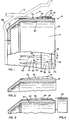
- the perferred brake drum 10 is mounted for rotation with a hub (not shown) supporting a wheel 12 of a heavy duty truck or trailer.
- the brake drum 10 includes the cylindrical braking drum 14 having an opened end 16 and a flange end 18 by which the brake drum 10 is secured to the hub.
- the wheel 12 with which the preferred brake drum 10 is associated is only slightly larger than the brake drum 10 and is of such a design which includes no significant openings or holes through the radial wall 20 thereof. In other words, where the rim portion of the wheel 12 to be significantly larger than the brake drum 10 or to include a plurality of openings in the radial wall 20, such as is found in spoked wheels, then the movement of cooling air about the brake drum 10 would not be considered as significant.
- the preferred brake drum 10 is provided a plurality of generally axially extending fins 26 around the exterior surface 22.
- the preferred fins 26 are not designed to extend helically about the exterior surface 22 but are instead provided a contour which will be seen to produce the desired flow of air therebetween.
- each of the fins 26 has radially extending side walls 28, 30 which diverge along a length thereof from the opened end 16 to have a widest distance therebetween at a predetermined location 32 from the opened end 16.
- the side walls 28, 30 converge along the length thereof from the predetermined location 32 to their terminal end at the flanged end 18 of the braking drum 14. Accordingly, adjacent side walls 30, 28-of adjacent fins 26 define a space 34 therebetween having its narrowest portion 36 at the predetermined location 32.
- a steel band 38 is secured to and encircles the braking drum 14 at the predetermined location 32.
- the steel band cooperates witn the adjacent side walls 30, 28 and the exterior surface 22 of the braking drum 14 to define a cooling air channel 40 at the narrowest portion 36 of each of the spaces 34.
- the predetermined location 32 and the encircling steel band 38 are located closer to the opened end 16 than the flanged end 18 of the braking drum 14. Locating the steel band 38 in this region significantly adds to the overall strength of the preferred brake drum 10 since the greater forces acting thereon will be experienced at the opened end 16. Further, since the steel band 38 will add significant strength to the brake drum 10 when compared to the cast iron which is utilized for the braking drum 14, the overall configuration is significantly stronger without adding unduly to the overall weight of the brake drum 10.
- the brake drum 10 is designed to primarily rotate in the direction as indicated by the arrow D. With the brake drum 10 primarily rotating in a counterclockwise direction when viewed from the right, a portion 42 of the side walls 30 of each of the fins 26 between the opened end 16 and the predetermined location 32 and facing toward the direction D extends axially.
- a corresponding portion 44 of the side walls 28 of each adjacent fin 26 between the opened end 14 and the predetermined location 32 and facing away from the normal direction D is inclined from the opened end 16 to the predetermined location 32 in a direction which is circumferentially opposite from the normal direction D of rotation. Accordingly, the space 34 is provided a converging profile at the opened end 16 which tends to scoop the air into the narrowest portion 36 thereof in order to ensure the venturi action on the air will be initiated for proper flow through the space 34.
- the cylindrical braking drum 14 is initially cast of iron as seen in Figure 2. Since the profile of the fins 26 do not include any portion thereof which overlap in an axial direction, the preferred braking drum 14 is cast with the axially extending fins 26 thereof being formed by dies which would meet at the predetermined location 32. As a result, the preferred cylindrical braking drum 14 can be manufactured in green sand without requiring cores during the casting operation.
- the cast braking drum 14 of Figure 2 is machined to provide the desired braking surface 24 and to remove the top 46 of the fins 26 in a location thereof for receipt of the steel band 38.
- a shoulder 48 is provided to establish the desired location of the end of the steel band 38.
- tne steel band 38 is formed in a continuous ring and is sized to be received on the surface at the top 46 of each of the fins 26. It has been found that there are two effective means for mounting and securing the steel band 38 on the fins 26. First, it is possible for the steel band 38 to be simply pressed fit over the top 46-until contact is made at the shoulder 48. However, depending on the desired dimensions of the brake drum 10 and the type of fit desired for the steel band 38 thereof, a second means includes heating the steel band to a temperature of 1000°F to 1100°F and then positioning the steel band at the predetermined location 32 as.described and allowing it to cool.
Landscapes
- Engineering & Computer Science (AREA)
- General Engineering & Computer Science (AREA)
- Mechanical Engineering (AREA)
- Braking Arrangements (AREA)
Applications Claiming Priority (2)
| Application Number | Priority Date | Filing Date | Title |
|---|---|---|---|
| US572273 | 1984-01-20 | ||
| US06/572,273 US4536936A (en) | 1984-01-20 | 1984-01-20 | Method of forming a brake drum |
Publications (2)
| Publication Number | Publication Date |
|---|---|
| EP0153996A1 true EP0153996A1 (de) | 1985-09-11 |
| EP0153996B1 EP0153996B1 (de) | 1989-04-26 |
Family
ID=24287089
Family Applications (1)
| Application Number | Title | Priority Date | Filing Date |
|---|---|---|---|
| EP84113104A Expired EP0153996B1 (de) | 1984-01-20 | 1984-10-31 | Verfahren zum Formen einer Bremstrommel |
Country Status (7)
| Country | Link |
|---|---|
| US (1) | US4536936A (de) |
| EP (1) | EP0153996B1 (de) |
| JP (1) | JPS60155020A (de) |
| BR (1) | BR8406384A (de) |
| CA (1) | CA1248332A (de) |
| DE (2) | DE3477957D1 (de) |
| MX (1) | MX161061A (de) |
Families Citing this family (3)
| Publication number | Priority date | Publication date | Assignee | Title |
|---|---|---|---|---|
| US5408724A (en) * | 1993-05-03 | 1995-04-25 | Wayne-Dalton Corporation | Jamb bracket and track assembly for sectional overhead doors |
| AU1419697A (en) * | 1995-12-07 | 1997-06-27 | Dayton-Walther Corporation | Brake drum having ribs on drum outer surface |
| US10316913B2 (en) * | 2015-09-24 | 2019-06-11 | Webb Wheel Products, Inc. | Vehicle brake drums having braking walls enhanced with compressive stresses |
Citations (3)
| Publication number | Priority date | Publication date | Assignee | Title |
|---|---|---|---|---|
| DE1661325U (de) * | ||||
| DE1042984B (de) * | 1954-04-03 | 1958-11-06 | Daimler Benz Ag | Leichtmetallbremstrommel mit eingegossenem eisernem Bremsring |
| GB1423892A (en) * | 1972-05-19 | 1976-02-04 | Motor Wheel Corp | Methods and apparatus for use in making annular compacts for vehicle brake drum rings and to brake drum rings |
Family Cites Families (6)
| Publication number | Priority date | Publication date | Assignee | Title |
|---|---|---|---|---|
| US2740502A (en) * | 1951-05-10 | 1956-04-03 | Chrysler Corp | Air cooled wheel brake |
| US2888105A (en) * | 1954-12-20 | 1959-05-26 | Bendix Aviat Corp | Composite disk and shoe brake |
| US3151709A (en) * | 1962-07-10 | 1964-10-06 | Troy Leonard | Brake drum |
| US3841448A (en) * | 1973-06-14 | 1974-10-15 | Budd Co | Reinforced brake drum |
| US4025751A (en) * | 1975-04-28 | 1977-05-24 | Xerox Corporation | Fuser roll sleeve |
| US4266638A (en) * | 1977-12-08 | 1981-05-12 | Ford Motor Company | Composite brake drum |
-
1984
- 1984-01-20 US US06/572,273 patent/US4536936A/en not_active Expired - Fee Related
- 1984-10-31 DE DE8484113104T patent/DE3477957D1/de not_active Expired
- 1984-10-31 EP EP84113104A patent/EP0153996B1/de not_active Expired
- 1984-10-31 DE DE198484113104T patent/DE153996T1/de active Pending
- 1984-11-30 CA CA000469056A patent/CA1248332A/en not_active Expired
- 1984-11-30 JP JP59253972A patent/JPS60155020A/ja active Granted
- 1984-12-12 BR BR8406384A patent/BR8406384A/pt unknown
-
1985
- 1985-01-04 MX MX203964A patent/MX161061A/es unknown
Patent Citations (3)
| Publication number | Priority date | Publication date | Assignee | Title |
|---|---|---|---|---|
| DE1661325U (de) * | ||||
| DE1042984B (de) * | 1954-04-03 | 1958-11-06 | Daimler Benz Ag | Leichtmetallbremstrommel mit eingegossenem eisernem Bremsring |
| GB1423892A (en) * | 1972-05-19 | 1976-02-04 | Motor Wheel Corp | Methods and apparatus for use in making annular compacts for vehicle brake drum rings and to brake drum rings |
Also Published As
| Publication number | Publication date |
|---|---|
| JPH0155813B2 (de) | 1989-11-27 |
| DE3477957D1 (en) | 1989-06-01 |
| US4536936A (en) | 1985-08-27 |
| CA1248332A (en) | 1989-01-10 |
| BR8406384A (pt) | 1985-10-08 |
| JPS60155020A (ja) | 1985-08-14 |
| EP0153996B1 (de) | 1989-04-26 |
| MX161061A (es) | 1990-07-18 |
| DE153996T1 (de) | 1986-07-24 |
Similar Documents
| Publication | Publication Date | Title |
|---|---|---|
| US5538113A (en) | Brake drum having irregularly spaced chill fins extending from a squealer band | |
| US6241056B1 (en) | Composite brake drum | |
| CA1081627A (en) | Braking disc with replaceable linings, for disc brakes | |
| US5161652A (en) | Ventilated disk brake rotor | |
| US4263992A (en) | Fabricated disc brake rotor assembly | |
| US6260669B1 (en) | Brake rotor with airflow director | |
| US6206150B1 (en) | Composite brake drum having a balancing skirt | |
| US5109960A (en) | Brake disk for disk brakes | |
| US6612656B2 (en) | Wheel mounting apparatus | |
| US20070199778A1 (en) | Vented disc brake rotor | |
| EP0155354B1 (de) | Bremstrommel | |
| US2769512A (en) | Brake rotor | |
| US3583533A (en) | Helically finned brake drum | |
| EP1342017B1 (de) | Gewichtsreduzierte scheibe für eine motorradscheibenbremse und entsprechendes herstellungsverfahren | |
| US4536936A (en) | Method of forming a brake drum | |
| US6962242B2 (en) | Brake rotor | |
| US4077501A (en) | Disc for disc brake unit | |
| US3003598A (en) | Brake drum | |
| US5915747A (en) | Method of making a rotor with vented hat section and an initial casting | |
| WO2002064992A2 (en) | An improved rotor for self-ventilating disc brakes | |
| US5320201A (en) | Truck brake drum with increased cooling | |
| US6666309B2 (en) | Truck brake drum | |
| US3151709A (en) | Brake drum | |
| JP3945825B2 (ja) | 自動車の車輪用ホイールハブ | |
| JPH0861403A (ja) | ブレーキロータ及びその鋳造用金型 |
Legal Events
| Date | Code | Title | Description |
|---|---|---|---|
| PUAI | Public reference made under article 153(3) epc to a published international application that has entered the european phase |
Free format text: ORIGINAL CODE: 0009012 |
|
| AK | Designated contracting states |
Designated state(s): DE FR GB IT |
|
| 17P | Request for examination filed |
Effective date: 19860310 |
|
| DET | De: translation of patent claims | ||
| 17Q | First examination report despatched |
Effective date: 19870703 |
|
| GRAA | (expected) grant |
Free format text: ORIGINAL CODE: 0009210 |
|
| AK | Designated contracting states |
Kind code of ref document: B1 Designated state(s): DE FR GB IT |
|
| REF | Corresponds to: |
Ref document number: 3477957 Country of ref document: DE Date of ref document: 19890601 |
|
| ITF | It: translation for a ep patent filed | ||
| ET | Fr: translation filed | ||
| PGFP | Annual fee paid to national office [announced via postgrant information from national office to epo] |
Ref country code: FR Payment date: 19890928 Year of fee payment: 6 Ref country code: DE Payment date: 19890928 Year of fee payment: 6 |
|
| PGFP | Annual fee paid to national office [announced via postgrant information from national office to epo] |
Ref country code: GB Payment date: 19890930 Year of fee payment: 6 |
|
| ITTA | It: last paid annual fee | ||
| PLBE | No opposition filed within time limit |
Free format text: ORIGINAL CODE: 0009261 |
|
| STAA | Information on the status of an ep patent application or granted ep patent |
Free format text: STATUS: NO OPPOSITION FILED WITHIN TIME LIMIT |
|
| 26N | No opposition filed | ||
| PG25 | Lapsed in a contracting state [announced via postgrant information from national office to epo] |
Ref country code: GB Effective date: 19901031 |
|
| GBPC | Gb: european patent ceased through non-payment of renewal fee | ||
| PG25 | Lapsed in a contracting state [announced via postgrant information from national office to epo] |
Ref country code: FR Effective date: 19910628 |
|
| PG25 | Lapsed in a contracting state [announced via postgrant information from national office to epo] |
Ref country code: DE Effective date: 19910702 |
|
| REG | Reference to a national code |
Ref country code: FR Ref legal event code: ST |