EP0154036A2 - Dispositif de commande pour papillon de gaz - Google Patents
Dispositif de commande pour papillon de gaz Download PDFInfo
- Publication number
- EP0154036A2 EP0154036A2 EP84116429A EP84116429A EP0154036A2 EP 0154036 A2 EP0154036 A2 EP 0154036A2 EP 84116429 A EP84116429 A EP 84116429A EP 84116429 A EP84116429 A EP 84116429A EP 0154036 A2 EP0154036 A2 EP 0154036A2
- Authority
- EP
- European Patent Office
- Prior art keywords
- throttle valve
- shaft
- motor
- opening degree
- rotor
- Prior art date
- Legal status (The legal status is an assumption and is not a legal conclusion. Google has not performed a legal analysis and makes no representation as to the accuracy of the status listed.)
- Granted
Links
Images
Classifications
-
- F—MECHANICAL ENGINEERING; LIGHTING; HEATING; WEAPONS; BLASTING
- F02—COMBUSTION ENGINES; HOT-GAS OR COMBUSTION-PRODUCT ENGINE PLANTS
- F02M—SUPPLYING COMBUSTION ENGINES IN GENERAL WITH COMBUSTIBLE MIXTURES OR CONSTITUENTS THEREOF
- F02M7/00—Carburettors with means for influencing, e.g. enriching or keeping constant, fuel/air ratio of charge under varying conditions
- F02M7/02—Carburettors having aerated fuel spray nozzles
-
- F—MECHANICAL ENGINEERING; LIGHTING; HEATING; WEAPONS; BLASTING
- F02—COMBUSTION ENGINES; HOT-GAS OR COMBUSTION-PRODUCT ENGINE PLANTS
- F02D—CONTROLLING COMBUSTION ENGINES
- F02D41/00—Electrical control of supply of combustible mixture or its constituents
- F02D41/0002—Controlling intake air
-
- F—MECHANICAL ENGINEERING; LIGHTING; HEATING; WEAPONS; BLASTING
- F02—COMBUSTION ENGINES; HOT-GAS OR COMBUSTION-PRODUCT ENGINE PLANTS
- F02D—CONTROLLING COMBUSTION ENGINES
- F02D11/00—Arrangements for, or adaptations to, non-automatic engine control initiation means, e.g. operator initiated
- F02D11/06—Arrangements for, or adaptations to, non-automatic engine control initiation means, e.g. operator initiated characterised by non-mechanical control linkages, e.g. fluid control linkages or by control linkages with power drive or assistance
- F02D11/10—Arrangements for, or adaptations to, non-automatic engine control initiation means, e.g. operator initiated characterised by non-mechanical control linkages, e.g. fluid control linkages or by control linkages with power drive or assistance of the electric type
-
- F—MECHANICAL ENGINEERING; LIGHTING; HEATING; WEAPONS; BLASTING
- F02—COMBUSTION ENGINES; HOT-GAS OR COMBUSTION-PRODUCT ENGINE PLANTS
- F02D—CONTROLLING COMBUSTION ENGINES
- F02D11/00—Arrangements for, or adaptations to, non-automatic engine control initiation means, e.g. operator initiated
- F02D11/06—Arrangements for, or adaptations to, non-automatic engine control initiation means, e.g. operator initiated characterised by non-mechanical control linkages, e.g. fluid control linkages or by control linkages with power drive or assistance
- F02D11/10—Arrangements for, or adaptations to, non-automatic engine control initiation means, e.g. operator initiated characterised by non-mechanical control linkages, e.g. fluid control linkages or by control linkages with power drive or assistance of the electric type
- F02D2011/101—Arrangements for, or adaptations to, non-automatic engine control initiation means, e.g. operator initiated characterised by non-mechanical control linkages, e.g. fluid control linkages or by control linkages with power drive or assistance of the electric type characterised by the means for actuating the throttles
- F02D2011/102—Arrangements for, or adaptations to, non-automatic engine control initiation means, e.g. operator initiated characterised by non-mechanical control linkages, e.g. fluid control linkages or by control linkages with power drive or assistance of the electric type characterised by the means for actuating the throttles at least one throttle being moved only by an electric actuator
-
- Y—GENERAL TAGGING OF NEW TECHNOLOGICAL DEVELOPMENTS; GENERAL TAGGING OF CROSS-SECTIONAL TECHNOLOGIES SPANNING OVER SEVERAL SECTIONS OF THE IPC; TECHNICAL SUBJECTS COVERED BY FORMER USPC CROSS-REFERENCE ART COLLECTIONS [XRACs] AND DIGESTS
- Y02—TECHNOLOGIES OR APPLICATIONS FOR MITIGATION OR ADAPTATION AGAINST CLIMATE CHANGE
- Y02T—CLIMATE CHANGE MITIGATION TECHNOLOGIES RELATED TO TRANSPORTATION
- Y02T10/00—Road transport of goods or passengers
- Y02T10/10—Internal combustion engine [ICE] based vehicles
- Y02T10/40—Engine management systems
Definitions
- the present invention relates to an apparatus for controlling the opening degree of a throttle valve of an internal combustion engine, and more particularly to the one of an automobile internal combustion engine.
- a motor and a throttle valve are separately provided, and an output shaft of a rotor portion of the motor is connected to a throttle valve shaft of the throttle valve through coupling means.
- the opening degree of the throttle valve is changed in accordance with a swing movement of the output shaft of the motor.
- the coupling means interposed between the motor and the throttle valve may not make a torque transmission from the output shaft of the motor to the throttle valve shaft surely, and/or may not make the throttle valve and/or the output shaft smoothly swing due to the difficulties in respect of precision of setting the throttle valve shaft and the output shaft of the motor.
- the present invention provides a throttle valve controlling apparatus in which a one-piece shaft includes a throttle valve shaft and the output shaft of the rotor portion of the motor.
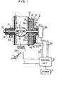
- a throttle valve controlling apparatus includes a throttle valve 2 provided in an induction cylinder 1 through which air-fuel mixture is supplied to an engine (E), and a motor 3 which is mounted on a portion of a peripheral wall surface of the induction cylinder 1.
- the throttle valve 2 is fixed to a one-piece throttle valve shaft 4 which extends diametrically through the induction cylinder 1.
- the throttle valve 2 is inserted into a diametrical through slit which is formed in the throttle valve shaft 4, and is located and fixed on the throttle valve shaft 4 by two screws (5).
- the throttle valve shaft 4 is carried at the opposite end portions thereof by ball bearings 6a, 6b, respectively.
- a dust seal 7 is disposed adjacent the ball bearing 6a at one end portion of the shaft 4 and around the shaft 4 such as to prevent dust from entering into the negative pressure cylinder 1.
- a torsion coil-spring 8 is so disposed that one end thereof is secured to the induction cylinder wall and the other end thereof is secured to the valve shaft 4.
- the torsion coil-spring 8 is mounted to urge the throttle valve 2 in a fully closed condition due to its return torque. Accordingly, even when the motor 3 gets out of order during the operation of the engine, the throttle valve 2 is returned to the fully closed condition and then the running of the engine is stopped.
- the reference numeral 9 represents a collar for retaining the torsion coil-spring 8 in an appropriate state.
- a rotor 10 of the motor 3 is closely mounted on the other end portion of the throttle valve shaft 4.
- the rotor 10 generally has a disk-like shape, and includes a commutator 11, a resinified armature winding 12 and a cylindrical base 13 carrying the resinified armature winding.
- the motor 3 further, includes a casing 14 which is composed of a mounting base 15 secured to the peripheral wall surface of the induction cylinder and a pan-shaped cover 16 fitted to the mounting base 15.
- Permanent magnets 9a, 9b are so secured to the mounting base 15 and the cover 16, respectively that the armature winding 12 is interposed between these magnets.
- the permanent magnets 9a, 9b are axially aligned to each other and are circumferentially equiangularly spaced.
- the radial intermediate portions of the opposite end surfaces of the disk-like armature winding 12 are provided with annular recesses 17, 17 into which the permanent magnets 9a, 9b extend. Accordingly the axial distance between the magnets 9a, 9b decreases and the magnetic flux density in the magnetic field of the motor 3 increases.
- a brush cover 18 which contains a brush 19 is attached to the cover 16. The brush 19 is urged by a spring 20 in the brush cover 18 and is press fitted into the commutator 11.
- Another brush appratus (not shown) of the same structure is also attached to the cover 16 at a position circumferentially spaced by 90 degrees in relation to the axis of the throttle valve shaft. Power (p) is supplied from the commutator 11 to the armature winding 12 through a control unit 21, lines 22 and the brushes 19.
- a detector 23 for detecting an opening degree of the throttle valve 2 is so disposed that the ball bearing 6b is interposed between the motor 3 and the detector 23.
- the detector 23 is fixed on the cover 16 of the motor casing 14. An amount of swing of the throttle valve shaft 4 is detected and a signal corresponding to the opening degree of the throttle valve 2 is fed to the control unit 21 by the detector 23 through lines 24.
- the detector 23 includes an encoder or a potentiometer.
- the control unit 21 receives signals from the detector 23 and another signals from a device for transmitting commands from an operator, such as an accelerator 25, and information (I) such as the number of revolutions of the engine shaft, the position of the change gear, or the pressure in the induction cylinder 1.
- the control unit 21 determines the desired opening degree of the throttle valve in accordance with the signals from the accelerator 25 and with the information representing the engine conditions, and supplies power (P) to the rotor 10 of the motor 3 such as to match the opening degree of the throttle valve 2 with the desired opening degree.
- the control of the opening degree of the throttle valve 2 is conducted by balancing the return torque of the torsion coil-spring 8 with the driving torque of the rotor 10, i.e., the driving torque of the throttle valve shaft 4. When it is required to more widely open the throttle valve, more current is supplied to the rotor 10 such as to open the throttle valve against the return torque of the torsion coil-spring 8.
- the signals from the detector 23 are fed back to the control unit 21, whereby the amount of the current to be supplied to the rotor is controlled.
- it is required to close the throttle valve less current is supplied to the rotor 10 so that the return torque of the torsion coil-spring 8 overcomes the driving torque of the rotor 10 and closes the throttle valve.
- the control unit 21 may detect any defect in the torsion coil-spring 8 by the fed back signals from the detector 23. The control unit 21 informs the operator of the trouble and at the same time controls the throttle valve by supplying a reversed current.
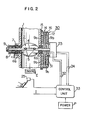
- a motor 30 has a rotor 31 without a commutator and permanent magnets 9a, 9b. Both ball bearings 6a, 6b are attached t6 the cylinder wall.
- the rotor 31 is disposed on a shaft portion between the ball bearing 6b and the detector 23-which is mounted on an end of a one piece throttle valve shaft 4.
- the rotor 31 generally has a disk-like shape and includes the armature winding 12.
- the armature winding 12 and the throttle valve shaft 4 are integrally impregnated with resins.
- the lead wires 32 of the winding 12 are directly connected to a control unit 33.
- the direction of the current which flows through the rotor is controlled by the commutator 11 and brushes 19, but in the other embodiment in Fig. 2, the current to be supplied to the rotor is controlled by the control unit 33 on the basis of the signals representing an error between a value of the desired opening degree of the throttle valve and the output from the detector.
- the apparatus can be made smaller than the one in Fig. 1, and the noise and wear caused by a contact between the commutator and the brushes of the embodiment shown in Fig. 1 can be eliminated, whereby its life is lengthened.
- the throttle valve and the rotor of the motor are mounted on the one-piece shaft, a swing movement of the throttle valve is made smoothly and effectively.
- the number of elements decreases due to a lack of the coupling means, so that a lower inertia and a rapid response are obtained.
Landscapes
- Engineering & Computer Science (AREA)
- Chemical & Material Sciences (AREA)
- Combustion & Propulsion (AREA)
- Mechanical Engineering (AREA)
- General Engineering & Computer Science (AREA)
- Control Of Throttle Valves Provided In The Intake System Or In The Exhaust System (AREA)
Applications Claiming Priority (2)
| Application Number | Priority Date | Filing Date | Title |
|---|---|---|---|
| JP59043946A JPS60190626A (ja) | 1984-03-09 | 1984-03-09 | 絞弁制御装置 |
| JP43946/84 | 1984-03-09 |
Publications (3)
| Publication Number | Publication Date |
|---|---|
| EP0154036A2 true EP0154036A2 (fr) | 1985-09-11 |
| EP0154036A3 EP0154036A3 (en) | 1985-12-18 |
| EP0154036B1 EP0154036B1 (fr) | 1990-04-11 |
Family
ID=12677869
Family Applications (1)
| Application Number | Title | Priority Date | Filing Date |
|---|---|---|---|
| EP84116429A Expired - Lifetime EP0154036B1 (fr) | 1984-03-09 | 1984-12-28 | Dispositif de commande pour papillon de gaz |
Country Status (6)
| Country | Link |
|---|---|
| US (1) | US4601271A (fr) |
| EP (1) | EP0154036B1 (fr) |
| JP (1) | JPS60190626A (fr) |
| KR (1) | KR850007640A (fr) |
| CA (1) | CA1236734A (fr) |
| DE (1) | DE3481931D1 (fr) |
Cited By (11)
| Publication number | Priority date | Publication date | Assignee | Title |
|---|---|---|---|---|
| WO1988002064A1 (fr) * | 1986-09-13 | 1988-03-24 | Robert Bosch Gmbh | Systeme pour le dosage regule d'air de combustion dans un moteur a combustion interne |
| EP0241841A3 (en) * | 1986-04-04 | 1988-07-27 | Mitsubishi Denki Kabushiki Kaisha | Throttle valve control device |
| EP0281466A1 (fr) * | 1987-02-23 | 1988-09-07 | Regie Nationale Des Usines Renault | Dispositif de motorisation d'un papillon rotatif |
| EP0313659A4 (fr) * | 1986-09-12 | 1988-12-01 | Mitsubishi Electric Corp | Regulateur de vanne a papillon. |
| EP0300153A3 (en) * | 1987-07-23 | 1989-03-29 | Vdo Adolf Schindling Ag | Load control apparatus |
| WO1989007707A1 (fr) * | 1988-02-18 | 1989-08-24 | Siemens Aktiengesellschaft | Actuateur d'etrangleur electronique |
| EP0341341A1 (fr) * | 1988-05-07 | 1989-11-15 | VDO Adolf Schindling AG | Dispositif de réglage de charge |
| EP0482284A1 (fr) * | 1990-10-24 | 1992-04-29 | VDO Adolf Schindling AG | Dispositif de réglage de charge |
| USRE40350E1 (en) | 1994-02-28 | 2008-06-03 | Borgwarner Inc. | Fail safe throttle positioning system |
| EP3153683A1 (fr) * | 2015-10-06 | 2017-04-12 | Kohler Co. | Actionneur de papillon pour moteur |
| US10815908B2 (en) | 2015-10-06 | 2020-10-27 | Kohler Co. | Throttle drive actuator for an engine |
Families Citing this family (42)
| Publication number | Priority date | Publication date | Assignee | Title |
|---|---|---|---|---|
| JPS61171843A (ja) * | 1985-01-24 | 1986-08-02 | Mazda Motor Corp | エンジンのスロツトル弁制御装置 |
| JPS61229935A (ja) * | 1985-04-04 | 1986-10-14 | Shikoo Giken:Kk | スロツトル弁調節機構 |
| JPH0759901B2 (ja) * | 1985-10-04 | 1995-06-28 | 株式会社日立製作所 | 絞弁の自動制御装置 |
| DE3618982A1 (de) * | 1986-06-05 | 1987-12-10 | Bosch Gmbh Robert | Stelleinrichtung fuer eine drosselklappe |
| JPS62298642A (ja) * | 1986-06-18 | 1987-12-25 | Honda Motor Co Ltd | 内燃エンジンの絞り弁制御装置 |
| JPS6385234A (ja) * | 1986-09-29 | 1988-04-15 | Mitsubishi Electric Corp | スロツトルバルブ制御装置 |
| JP2913637B2 (ja) * | 1987-04-23 | 1999-06-28 | アイシン精機株式会社 | スロツトルコントロール装置 |
| JPH057472Y2 (fr) * | 1987-06-03 | 1993-02-25 | ||
| US4831985A (en) * | 1988-02-17 | 1989-05-23 | Mabee Brian D | Throttle control system |
| US4869220A (en) * | 1988-02-18 | 1989-09-26 | Siemens-Bendix Automotive Electronics L.P. | Accelerator control apparatus |
| JPH01232128A (ja) * | 1988-03-11 | 1989-09-18 | Kiyousan Denki Kk | エンジンのスロットル弁制御装置 |
| US4850322A (en) * | 1988-03-31 | 1989-07-25 | Eaton Corporation | Method and apparatus for positioning a torque motor armature |
| JP2513776B2 (ja) * | 1988-04-01 | 1996-07-03 | 株式会社日立製作所 | スロットル弁制御方法及びその装置 |
| JPH02140419A (ja) * | 1988-04-19 | 1990-05-30 | Nippon Denso Co Ltd | 内燃機関の吸気制御装置及びそれを有する内燃機関 |
| JP2559480B2 (ja) * | 1988-11-07 | 1996-12-04 | 株式会社日立製作所 | 電子式弁開度制御装置 |
| US5013930A (en) * | 1989-03-29 | 1991-05-07 | General Motors Corporation | Remote control lever module |
| US4944269A (en) * | 1989-09-18 | 1990-07-31 | Siemens-Bendix Automotive Electronics L.P. | Accelerating pedal for electronic throttle actuation system |
| USRE34302E (en) * | 1989-09-18 | 1993-07-06 | Siemens Automotive L.P. | Accelerating pedal for electronic throttle actuation system |
| US5163400A (en) * | 1990-01-16 | 1992-11-17 | Sawafuji Electric Co. Ltd. | Engine unit |
| US5233882A (en) * | 1990-07-12 | 1993-08-10 | General Motors Corporation | Remote control lever module |
| US5199401A (en) * | 1991-10-21 | 1993-04-06 | Eaton Corporation | Engine throttle servoactuator control system |
| US5311849A (en) * | 1992-07-14 | 1994-05-17 | Gas Research Institute | Carburetor assembly for an internal combustion gas engine |
| CN1148881A (zh) * | 1995-02-10 | 1997-04-30 | 菲利浦电子有限公司 | 操作控制件的装置 |
| DE19505407A1 (de) * | 1995-02-17 | 1996-08-22 | Audi Ag | Verfahren zur Beheizung eines Drosselklappenstutzens |
| KR0125898B1 (ko) * | 1995-08-30 | 1997-12-18 | 전성원 | 자동차용 드로틀 밸브 무와이어 컨트롤 시스템 |
| WO1997009659A1 (fr) * | 1995-09-05 | 1997-03-13 | Cts Corporation | Capteur de position rotatif avec enroulement moule insere |
| US5823165A (en) * | 1996-02-23 | 1998-10-20 | Unisia Jecs Corporation | Valve actuator arrangement for internal combustion engine |
| DE19644169A1 (de) * | 1996-10-24 | 1998-04-30 | Mannesmann Vdo Ag | Lastverstelleinrichtung |
| SE518099C2 (sv) | 1997-11-21 | 2002-08-27 | Claes Johansson Automotive Ab | Inställbart pedalställ för ett fordon |
| US6244565B1 (en) | 1999-01-29 | 2001-06-12 | Ford Global Technologies, Inc. | Throttle body shaft axial play control |
| US6070852A (en) * | 1999-01-29 | 2000-06-06 | Ford Motor Company | Electronic throttle control system |
| US6095488A (en) * | 1999-01-29 | 2000-08-01 | Ford Global Technologies, Inc. | Electronic throttle control with adjustable default mechanism |
| US6155533C1 (en) * | 1999-01-29 | 2002-07-30 | Visteon Global Tech Inc | Default mechanism for electronic throttle control system |
| US6541881B1 (en) * | 1999-02-17 | 2003-04-01 | Eaton Corporation | Integral throttle body and torque motor |
| US6158417A (en) * | 1999-03-01 | 2000-12-12 | Visteon Global Technologies, Inc. | Throttle body accomodation of either an idle air control valve or a motorized throttle control |
| US6299545B1 (en) | 1999-05-03 | 2001-10-09 | Visteon Global Tech., Inc. | Rotating shaft assembly |
| US6173939B1 (en) | 1999-11-10 | 2001-01-16 | Ford Global Technologies, Inc. | Electronic throttle control system with two-spring failsafe mechanism |
| US6267352B1 (en) | 1999-11-11 | 2001-07-31 | Ford Global Technologies, Inc. | Electronic throttle return mechanism with default and gear backlash control |
| US6253732B1 (en) | 1999-11-11 | 2001-07-03 | Ford Global Technologies, Inc. | Electronic throttle return mechanism with a two-spring and two-lever default mechanism |
| US6286481B1 (en) | 1999-11-11 | 2001-09-11 | Ford Global Technologies, Inc. | Electronic throttle return mechanism with a two-spring and one lever default mechanism |
| US7159563B1 (en) * | 2005-10-28 | 2007-01-09 | Delphi Technologies, Inc. | Piezo electronic throttle control actuator |
| DE102006001242A1 (de) * | 2006-01-10 | 2007-07-12 | Tyco Electronics Amp Gmbh | Berührungsloser Positionsaufnehmer mit reversibler Selbst-Justage |
Family Cites Families (8)
| Publication number | Priority date | Publication date | Assignee | Title |
|---|---|---|---|---|
| DE1202571B (de) * | 1961-03-30 | 1965-10-07 | Helmut W Hotz | Regeleinrichtung fuer die Brennstoffzufuhr an Brennkraftmaschinen |
| DE2839467C2 (de) * | 1978-09-11 | 1985-01-31 | Vdo Adolf Schindling Ag, 6000 Frankfurt | Einrichtung zur Übertragung der Stellung eines die Fahrgeschwindigkeit eines Kraftfahrzeugs steuernden, durch den Fahrzeugführer betätigbaren Steuerelements |
| JPS56101026A (en) * | 1979-12-31 | 1981-08-13 | Heinzmann Gmbh Co Kg Fritz | Regulator for number of revolution of internal combustion engine |
| GB2071426B (en) * | 1980-03-05 | 1983-10-26 | Ford Motor Co | Carburettors inductive couplings |
| DE3039521A1 (de) * | 1980-10-20 | 1982-05-19 | Vdo Adolf Schindling Ag, 6000 Frankfurt | Einrichtung zur regelung der leerlaufdrehzahl von otto-motoren, insbesondere von kraftfahrzeugmotoren |
| DE3200096A1 (de) * | 1982-01-05 | 1983-07-14 | Robert Bosch Gmbh, 7000 Stuttgart | Stelleinrichtung |
| DE3237535A1 (de) * | 1982-10-09 | 1984-04-12 | Vdo Adolf Schindling Ag, 6000 Frankfurt | Einrichtung zum steuern der fahrgeschwindigkeit eines kraftfahrzeuges |
| US4523565A (en) * | 1984-03-30 | 1985-06-18 | Aisin Seiki Kabushiki Kaisha | Control system and method for a fuel delivery system |
-
1984
- 1984-03-09 JP JP59043946A patent/JPS60190626A/ja active Pending
- 1984-12-28 EP EP84116429A patent/EP0154036B1/fr not_active Expired - Lifetime
- 1984-12-28 DE DE8484116429T patent/DE3481931D1/de not_active Expired - Lifetime
- 1984-12-31 US US06/687,726 patent/US4601271A/en not_active Expired - Fee Related
- 1984-12-31 CA CA000471252A patent/CA1236734A/fr not_active Expired
-
1985
- 1985-03-09 KR KR1019850001510A patent/KR850007640A/ko not_active Ceased
Cited By (18)
| Publication number | Priority date | Publication date | Assignee | Title |
|---|---|---|---|---|
| EP0241841A3 (en) * | 1986-04-04 | 1988-07-27 | Mitsubishi Denki Kabushiki Kaisha | Throttle valve control device |
| EP0313659A4 (fr) * | 1986-09-12 | 1988-12-01 | Mitsubishi Electric Corp | Regulateur de vanne a papillon. |
| EP0326553B1 (fr) | 1986-09-13 | 1990-12-27 | Robert Bosch Gmbh | Systeme pour le dosage regule d'air de combustion dans un moteur a combustion interne |
| WO1988002064A1 (fr) * | 1986-09-13 | 1988-03-24 | Robert Bosch Gmbh | Systeme pour le dosage regule d'air de combustion dans un moteur a combustion interne |
| FR2611811A1 (fr) * | 1987-02-23 | 1988-09-09 | Renault | Dispositif de motorisation d'un papillon rotatif |
| EP0281466A1 (fr) * | 1987-02-23 | 1988-09-07 | Regie Nationale Des Usines Renault | Dispositif de motorisation d'un papillon rotatif |
| EP0300153A3 (en) * | 1987-07-23 | 1989-03-29 | Vdo Adolf Schindling Ag | Load control apparatus |
| WO1989007707A1 (fr) * | 1988-02-18 | 1989-08-24 | Siemens Aktiengesellschaft | Actuateur d'etrangleur electronique |
| EP0341341A1 (fr) * | 1988-05-07 | 1989-11-15 | VDO Adolf Schindling AG | Dispositif de réglage de charge |
| EP0482284A1 (fr) * | 1990-10-24 | 1992-04-29 | VDO Adolf Schindling AG | Dispositif de réglage de charge |
| US5193503A (en) * | 1990-10-24 | 1993-03-16 | Vdo Adolf Schindling Ag | Load adjustment device |
| USRE40350E1 (en) | 1994-02-28 | 2008-06-03 | Borgwarner Inc. | Fail safe throttle positioning system |
| EP3153683A1 (fr) * | 2015-10-06 | 2017-04-12 | Kohler Co. | Actionneur de papillon pour moteur |
| CN107013344A (zh) * | 2015-10-06 | 2017-08-04 | 科勒公司 | 用于引擎的节气门驱动致动器 |
| CN107013344B (zh) * | 2015-10-06 | 2020-03-24 | 科勒公司 | 用于引擎的节气门驱动致动器 |
| US10815908B2 (en) | 2015-10-06 | 2020-10-27 | Kohler Co. | Throttle drive actuator for an engine |
| US11408358B2 (en) | 2015-10-06 | 2022-08-09 | Kohler Co. | Throttle drive actuator for an engine |
| US12448926B2 (en) | 2015-10-06 | 2025-10-21 | Discovery Energy, Llc | Throttle drive actuator for an engine |
Also Published As
| Publication number | Publication date |
|---|---|
| EP0154036B1 (fr) | 1990-04-11 |
| KR850007640A (ko) | 1985-12-07 |
| EP0154036A3 (en) | 1985-12-18 |
| US4601271A (en) | 1986-07-22 |
| DE3481931D1 (de) | 1990-05-17 |
| JPS60190626A (ja) | 1985-09-28 |
| CA1236734A (fr) | 1988-05-17 |
Similar Documents
| Publication | Publication Date | Title |
|---|---|---|
| EP0154036A2 (fr) | Dispositif de commande pour papillon de gaz | |
| US7367315B2 (en) | Throttle valve control apparatus of internal combustion engine and automobile using the same | |
| US4723753A (en) | Flow rate control valve system | |
| KR100226032B1 (ko) | 드로틀밸브 제어장치 | |
| EP1050673B2 (fr) | Dispositif de commande de débit d'air | |
| EP1267057B1 (fr) | Dispositif de commande de l'air d'admission pour un moteur à combustion interne | |
| US4723754A (en) | Flow rate control valve system | |
| US4999531A (en) | Electromagnetic actuators | |
| CN100396898C (zh) | 设有扁平板簧和螺旋弹簧以建立惰行复位位置的电控蝶形阀 | |
| US5239961A (en) | Rotary idle-speed actuator | |
| US6892698B2 (en) | Throttle control heat dissipation device | |
| EP0033136B1 (fr) | Distributeur comprenant une bobine d'allumage | |
| US20040041118A1 (en) | Throttle-valve | |
| US4903525A (en) | Rotational position sensor device for internal combustion engine | |
| US5163400A (en) | Engine unit | |
| EP1408219A1 (fr) | Dispositif de commande de papillon de valve à moteur et methode de montage du moteur | |
| EP1375869A2 (fr) | Dispositif d'étranglement | |
| EP0379356A1 (fr) | Dispositif pour détecter le mouvement | |
| JPS62264887A (ja) | ロボツトの回転検出機構 | |
| JPH0544523A (ja) | 回転センサ内蔵スタータ | |
| JPH0522424Y2 (fr) | ||
| JPS60252130A (ja) | 液没式エンジンの調速装置 | |
| JPS5857540A (ja) | 可変容量フライホイ−ル装置 | |
| JPS61244852A (ja) | アイドル回転数制御装置 | |
| JPH06264779A (ja) | 内燃機関の絞り弁制御装置 |
Legal Events
| Date | Code | Title | Description |
|---|---|---|---|
| PUAI | Public reference made under article 153(3) epc to a published international application that has entered the european phase |
Free format text: ORIGINAL CODE: 0009012 |
|
| AK | Designated contracting states |
Designated state(s): CH DE FR GB IT LI NL SE |
|
| PUAL | Search report despatched |
Free format text: ORIGINAL CODE: 0009013 |
|
| AK | Designated contracting states |
Designated state(s): CH DE FR GB IT LI NL SE |
|
| 17P | Request for examination filed |
Effective date: 19851219 |
|
| 17Q | First examination report despatched |
Effective date: 19861203 |
|
| GRAA | (expected) grant |
Free format text: ORIGINAL CODE: 0009210 |
|
| AK | Designated contracting states |
Kind code of ref document: B1 Designated state(s): DE GB |
|
| REF | Corresponds to: |
Ref document number: 3481931 Country of ref document: DE Date of ref document: 19900517 |
|
| EN | Fr: translation not filed | ||
| PLBE | No opposition filed within time limit |
Free format text: ORIGINAL CODE: 0009261 |
|
| STAA | Information on the status of an ep patent application or granted ep patent |
Free format text: STATUS: NO OPPOSITION FILED WITHIN TIME LIMIT |
|
| 26N | No opposition filed | ||
| PGFP | Annual fee paid to national office [announced via postgrant information from national office to epo] |
Ref country code: GB Payment date: 19931217 Year of fee payment: 10 |
|
| PGFP | Annual fee paid to national office [announced via postgrant information from national office to epo] |
Ref country code: DE Payment date: 19940228 Year of fee payment: 10 |
|
| PG25 | Lapsed in a contracting state [announced via postgrant information from national office to epo] |
Ref country code: GB Effective date: 19941228 |
|
| GBPC | Gb: european patent ceased through non-payment of renewal fee |
Effective date: 19941228 |
|
| PG25 | Lapsed in a contracting state [announced via postgrant information from national office to epo] |
Ref country code: DE Effective date: 19950901 |