EP0154078A2 - Appareil de traitement par plasma - Google Patents
Appareil de traitement par plasma Download PDFInfo
- Publication number
- EP0154078A2 EP0154078A2 EP84307421A EP84307421A EP0154078A2 EP 0154078 A2 EP0154078 A2 EP 0154078A2 EP 84307421 A EP84307421 A EP 84307421A EP 84307421 A EP84307421 A EP 84307421A EP 0154078 A2 EP0154078 A2 EP 0154078A2
- Authority
- EP
- European Patent Office
- Prior art keywords
- cathode
- magnetic field
- sample
- treatment apparatus
- plasma treatment
- Prior art date
- Legal status (The legal status is an assumption and is not a legal conclusion. Google has not performed a legal analysis and makes no representation as to the accuracy of the status listed.)
- Withdrawn
Links
Images


Classifications
-
- H—ELECTRICITY
- H01—ELECTRIC ELEMENTS
- H01J—ELECTRIC DISCHARGE TUBES OR DISCHARGE LAMPS
- H01J37/00—Discharge tubes with provision for introducing objects or material to be exposed to the discharge, e.g. for the purpose of examination or processing thereof
- H01J37/32—Gas-filled discharge tubes
- H01J37/34—Gas-filled discharge tubes operating with cathodic sputtering
- H01J37/3411—Constructional aspects of the reactor
- H01J37/345—Magnet arrangements in particular for cathodic sputtering apparatus
- H01J37/3458—Electromagnets in particular for cathodic sputtering apparatus
-
- H—ELECTRICITY
- H01—ELECTRIC ELEMENTS
- H01J—ELECTRIC DISCHARGE TUBES OR DISCHARGE LAMPS
- H01J37/00—Discharge tubes with provision for introducing objects or material to be exposed to the discharge, e.g. for the purpose of examination or processing thereof
- H01J37/32—Gas-filled discharge tubes
- H01J37/34—Gas-filled discharge tubes operating with cathodic sputtering
- H01J37/3402—Gas-filled discharge tubes operating with cathodic sputtering using supplementary magnetic fields
- H01J37/3405—Magnetron sputtering
- H01J37/3408—Planar magnetron sputtering
Definitions
- This invention relates to an apparatus for plasma treatment (hereafter referred to as "a plasma treatment apparatus") applied in the manufacture of, for example, a semiconductor device, optical recording disk, etc., and more particularly, to a plasma treatment apparatus for effecting, for example, high speed etching and film formation by magnetron discharges.
- a plasma treatment apparatus for plasma treatment
- a plasma treatment apparatus for effecting, for example, high speed etching and film formation by magnetron discharges.
- RIE reactive ion etching
- the RIE method using the above-mentioned parallel electrode plates involves the application of glow discharges having a relatively low gas- dissociating effect.
- a Si0 2 sample is etched by means of, for example, a reactive gas consisting of CF 4 and H 2
- the rate at which said Si 02 sample is etched only ranges between 300 and 400 A/min at most. Therefore, it takes longer than several minutes to etch an Si0 2 layer having a thickness of 1 micron in the production of, for example, a contact hole. Consequently, a demand has been made for the acceleration of the etching speed.
- a dry etching apparatus wherein a magnetic field-generating means, for example, a permanent magnet, is set below a cathode supplied with a high frequency power, and which effects high speed etching by magnetron discharges.
- a magnetic field-generating means for example, a permanent magnet
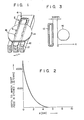
- Fig. 2 is a curved diagram showing the results of measuring the rate at which the Si0 2 layer was etched by the reactive gas C F4 (the depth attained by the 10 sec. etching) as a function of a distance measured from the edge of the sample.
- the intermagnetic pole region 12 remained at rest at a point 30 mm from the edge of the sample 14 (see Fig. 3).
- Fig. 2 shows that the 10 see etching in the proximity of the sample edge realized etching with a depth of about 1,000 to 2,000 A, and the etching was carried out at a lower speed toward a region lying more inside the sample edge. Even if it is supposed that scanning is carried out so quickly that one reciprocation of the scanning takes only 0.05 second, the etching rate will be equivalent to the fact that the intermagnetic pole region 12 is brought to rest on both sides of the sample 14 for 2 seconds during each cycle of about 80 scanning reciprocations. In this case, the sample edge is etched with a depth of about 500 A.
- Such speedy etching of the peripheral portions of the sample will reduce the uniformity of the etching of the whole sample. It may be contemplated to broaden the intermagnetic pole region 12 as a means for preventing the occurrence of such an objectionable event. If X (Fig. 2) measures 50 mm, the sample will not be etched, even when the intermagnetic pole region 12 stands at rest. If, therefore, the intermagnetic pole region 12 is scanned at a distance of 80 mm from the sample,.then the sample can be uniformly etched. However, such an attempt will be accompained with the drawbacks that the plasma treatment apparatus will grow large, the etching rate will be reduced, and consequently, it will be difficult to treat the sample with plasma when the diameter of the sample becomes large (over 6 inches).
- This invention has been accomplished in view of the above-mentioned circumstances and is intended to provide a plasma treatment apparatus capable of uniformly treating a sample at a high speed without being enlarged in size.
- Another object of the invention is to provide a dry etching apparatus capable of uniformly etching a sample at a high speed.
- Still another object of the invention is to provide a vapor phase growth apparatus or sputtering apparatus capable of depositing a film on a sample with a uniform thickness.
- Still another object of the invention is to provide a plasma treatment apparatus capable of treating a sample with a large diameter.
- this invention provides a plasma treatment apparatus capable of treating a sample by ionizing an excited gas which comprises a housing having a chamber therein, an anode and a cathode which faces said anode.
- a sample to be treated is set between the cathode and anode or on the cathode or anode or at a point removed therefrom.
- a gas to be activated is introduced from a gas source into said chamber.
- a high frequency power source applies a high frequency voltage between the cathode and anode to generate an electric field, thereby producing a plasma.
- a magnetic field-generating means which involves a magnetic core consisting of a plurality of magnetic pole sections arranged in a first direction which is along the surface of the cathode, a plurality of coils provided to the magnetic core and respectively generating a magnetic field which has a component perpendicularly intersecting the electric field, and means for supplying alternative currents having different phases through said coils.
- the plasma treatment apparatus embodying this invention offers the advantages that a high density plasma region is always scanned in a direction by the magnetic field-generating means constituted by the magnetic core and a plurality of coils; therefore, a sample set on the cathode can be entirely ethced at a high speed.
- the drawback is eliminated in that the peripheral portions of a sample are etched at a particularly high speed as has been observed in the case where the intermagnetic pole region is subjected to reciprocating scanning in the conventional plasma treatment apparatus; therefore, the entire sample is always uniformly etched.
- a film can be deposited by vapor growth on a sample set on the cathode with a uniform thickness.
- a target set on the cathode When a sample to be covered with a film is placed on the anode, a target set on the cathode can be uniformly etched at a high speed; therefore, a film can be deposited on the sample uniformly and at a high speed. Since a high density plasma is electrically scanned, in other words, a magnetic field can be continuously shifted in one direction with the magnetic field-generating means kept immovable, the subject plasma treatment apparatus can be miniaturized. For the reason given above, it is unnecessary to provide mechanically movable members, and the subject plasma treatment apparatus is noticeably improved in reliability, and therefore, is well adapted for the manufacturing of, for example, a semiconductor device, optical recording disc, etc., and further can be easily applied in treating a large diameter sample.
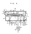
- Fig. 4 shows a dry etching apparatus according to a first embodiment of this invention.
- a housing 20 is grounded.
- the interior of the housing 20 is divided into an etching chamber 34 and a magnetic field-generating chamber 36. It is preferred that a pressure prevailing in the interior of said chamber 36 be made lower than the atmospheric pressure to suppress the occurrence of discharges in said chamber 36.
- Sandwiched between the cathode 24 and the wall 22 of the housing 20 is an insulation member 28 prepared from an insulating material such as fluorine-containing resin.
- the cathode 24 is insulated from the housing 20.
- An O-ring 30 is interposed between the cathode 24 and insulation material 28, thereby shutting a space between the etching chamber 34 and magnetic field-generating chamber 36 in a gas-tight fashion.
- a cooling water duct is formed in the cathode 24.
- This duct is connected to an external cooling water source through a pipe 26 prepared from a conductive material.
- an insulating member 32 prepared from the same insulation material as that of the insulation member 28 to ensure insulation between the pipe 26 and housing 20.
- Connected to said pipe 26 is a high frequency power source 43 through . a matching circuit 44, thereby allowing for the conduction of power to the cathode 24.
- the upper wall of the housing 20 faces the cathode 24 in a parallel relationship, and functions as an anode.
- the housing 20 is provided with a port 38 through which CF 4 gas is brought into the etching chamber 34. When excited, said CF 4 gas generates reactive ions.
- the housing 20 is provided with an exhaust port 40 connected to an evacuation device such as a vacuum pump in order to evacuate the interior of the etching chamber 34.
- a magnetic field generator 60 Installed in the magnetic field-generating chamber 36 below the cathode 24 is a magnetic field generator 60 which produces a movable magnetic field.
- the housing 20 is further provided with an exhaust port 42 connected to an evacuation device such as a vacuum pump in order to evacuate the interior of the magnetic field-generating chamber 36.
- the vacuum pump maintains the interior of said magnetic field-generating chamber 36 at a vacuum of about 10 -4 torr.
- the intermediate wall 22 of the housing 20 is provided with a ventilation port 29.
- a partition valve 45 fitted to the underside of the intermediate wall 22 to cover the ventilation port 29 is connected to an electromagnetic valve 52 by means of a support rod 48. This support rod 48 is insulated from the housing 20 by an insulating material 50.
- the partition valve 45 opens or closes the ventilation port 29, depending on the operation of the electromagnetic valve 52.
- An O-ring 46 is fitted to the underside of the wall 22 around the ventilation port 29. When the partition valve 46 is pressed against the underside of the wall 22, the etching chamber 34 and magnetic field-generating chamber 36 are separated from each other in a gas-tight fashion.
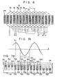
- F ig. 5 is an oblique view of the magnetic core 62.
- Fig. 6 shows the relative positions of the magnetic pole sections 64 constituting said magnetic core 62 and the coils.
- Fig. 7(b) is a sectional view of the magnetic core 62 in its lengthwise direction (indicated by an arrow 1 in Fig. 5).
- the magnetic generator 60 comprises the magnetic core 62 and a group 70 of coils (Fig. 6).
- the magnetic core 62 is constituted by a flat base 66 and a plurality of (16 indicated) parallel magnetic pole plates (64a ... 64p) integrally erected on said base 66.
- the longitudinal section of the magnetic core 62 presents a comb pattern.
- This comb-shaped magnetic core 62 can be fabricated by cutting out parallel grooves across a flat magnetic block.
- the width (indicated by arrow 2 in Fig. 5) of the magnetic pole sections 64 is longer than the diameter of a sample 100 (shaped like, for example, a disc) set on the cathode 24.
- the length (indicated by an arrow 1 in Fig. 5) of the base 66 is longer than the diameter of said sample 100.
- a cooling water duct is formed in the magnetic core 62. This duct communicates a pipe 68 connected to a cooling water source (not shown). The cooling water runs through said pipe 68 into the magnetic core 62 for cooling.
- the pipe 68 (not shown in Fig. 4) extends to the outside, while being insulated from the housing 20.
- the magnetic coil group 70 comprises four coils 72a, 72b, 72c and 72d (coils 72) shown in solid lines, four coils 74a, 74b, 74c and 74d (coils 74) indicated in broken lines, and four coils 76a, 76b, 76c and 76d (coils 76) set forth in dot-dash lines.
- the coil 72a surrounds the whole block of the magnetic pole sections 64b, 64c and 64d several times. Therefore, the conductor of said coil 72a lies between the magnetic pole sections 64a and 64b and also between the magnetic pole sections 64d and 64e.
- the coil 74a surrounds the whole block of the magnetic pole sections 64c, -64d and 64e several times.
- the conductor of said coil 74a lies between the magnetic pole sections 64b and 64c and also between the magnetic pole sections 64e and 64f.
- the conductors of said other coils 76a, 72b, 74b, 76b ... lie between the adjacent pole sections.
- the coils 72a, 72b, 72c and 72d are connected to each other.
- the coils 74a, 74b, 74c and 74d are connected to each other.
- the coils 76a, 76b, 76c and 76d are also connected to each other.
- the coil groups 72, 74 and 76 are connected to a 3-phase A.C. source 82 through a switch-80 (Fig. 4).
- the coils 72, 74 and 76 are respectively supplied with AC currents having different phases.
- the switch 80 effects changeover between the connections of the U, V and W terminals of the 3-phase AC source 82 to the coils 72, 74 and 76.
- the connections of the coils 72, 74 and 76 to said power source 82 are changed over between the case where the coils 72, 74 and 76 are applied with progressively higher voltages in the order mentioned and the case where the coils 76, 74 and 72 are applied with progressively higher voltages in the order mentioned.
- the pole pitch is herein defined to mean a half wavelength, the form in which the magnetic flux density distirubiton varies, namely, the length of half the period during which the magnetic flux varies.
- the magnetic flux B given in the previously mentioned equation 1 shows that a magnetic field having a magnetic flux density distribution shown in Fig. 7A is progressively shifted with time T to the right of Figs. 7A and 7B.
- the high and low levels of a magnetic field, acting lengthwise (in the direction of arrow 1 given in Fig. 4) of the magnetic field generator 60 appear alternately.
- the generation of the above-mentioned magnetic field leads to the production of a high density plasma region on the cathode 24.
- the movement of said magnetic field causes said plasma region to be continuously shifted in the direction of arrow 1.
- CF 4 gas is taken into the etching chamber 34 through the gas inlet port 38 to fill said chamber 34 with CF 4 gas having a pressure of 10 -2 torr. While the above-mentioned condition is preserved, high frequency voltage (13.56 MHz) is impressed on the cathode 24 from the high frequency power source 43. At this time, an electric field E is generated between the cathode 24 and the anode (constituted by the upper wall of the etching chamber 34), thereby giving rise to glow discharges and a low density plasma region 102.
- the dry etching apparatus embodying this invention offers the advantages that the sample 100 can be etched quickly and uniformly by the action of the magnetic field generator 60.
- This magnetic field generator 60 may have a size slightly lower than the sample 100, making it unnecessary to apply a large size plasma treatment apparatus.
- the omission of mechanically movable parts improves the reliable operation of the subjected plasma treatment apparatus and also ensures its miniaturization. Since the sample 100 is always exposed to the high density plasma region 104, an etching rate is decreased very little even when said sample happens to have a large diameter. Therefore, etching can be carried out at the same rate (about 5 microns/min) as when the intermagnetic pole region is brought to rest.
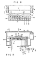
- FIG. 8 A description may now be made with reference to Fig. 8 of a dry etching apparatus according to a second embodiment of this invention.
- This second embodiment is different from the first embodiment in that Helmholtz coils 112 and 114 are provided on the cathode 24. In other respects, the second embodiment is exactly the same as the first embodiment.
- FIG. 9 A description may now be made with reference to F ig. 9 of a dry etching apparatus according to a third embodiment of this invention.
- the same parts of Fig. 9 as those of Fig. 4 are denoted by the same numerals, a description thereof being omitted.
- the third embodiment of Fig. 9 is different from the first embodiment in that the magnetic field generator 60 is set in the atmosphere. Namely, the cathode 24 is fixed on the upper end of the upright wall 122 of the housing with an insulation material 124 interposed therebetween. An O-ring is provided between the cathode 24 and the upright wall 122.
- a plasma treatment apparatus embodying this invention which involves the magnetic field generator 60, offers the advantages that etching is carried out at a prominently larger rate than in the conventional apparatus, even when the intensity of a magnetic field generated in the intermagnetic pole region and the magnitude of a high frequency power are reduced, the cathode 24 can be made sufficiently thick (more than 10 mm), and the magnetic field generator 60 is substantially saved from the occurrence of discharges, even if the highly evacuated chamber 36 is not provided to hold a magnetic field generator. Therefore, the third embodiment of Fig. 9 offers the advantages that the same effect as in the preceding embodiment is ensured, and the subject plasma treatment apparatus can be simplified in its arrangement.
- FIG. 10 A description may now be made with reference to Fig. 10 of a dry etching apparatus according to a fourth embodiment of this invention.
- the same parts of Fig. 10 as those of Fig. 4 are denoted by the-same numerals, a description thereof being omitted.
- the fourth embodiment is different from the first embodiment in that magnetic members 130 (for example, an iron plate) are embedded in that portion of the surface of the cathode 24 which faces the etching chamber 34. Namely, on the surface of the cathode 24, magnetic members 130 are embedded ahead and behind the region on which the sample 100 is placed, as viewed from the direction in which the magnetic field is scanned.
- the magnetic field generator 60 offers the advantages that even when the end of the magnetic field generator 60 lies under the magnetic member 130, the greater part of the magnetic flux passes through the highly permeable magnetic member 130, thereby suppressing the generation of a magnetic field above said magnetic member 130; therefore, the high density plasma region 104 surrounding the sample 100 is eliminated, a magnetic field can take a more uniform action in its prescribed moving direction, and etching can be carried out at a more uniform rate.
- the aforementioned magnetic field generator need not comprise a 3-phase winding type coil.
- the coil may be changed, for example, into a 2-phase winding type.
- the magnetic field generator well serves the purpose, provided said generator consists of a magnetic core and a plurality of coils and is so arranged that a magnetic field generated on the cathode can be continuously shifted in one direction.
- the size of the grooves formed in the magnetic core and the intervening space can be properly changed, depending on the manner on which the subject dry etching apparatus is applied.
- This arrangement elevates the capacity of the dry etching apparatus.
- the subject dry etching apparatus is applicable to the etching of not only a Si0 2 layer but also any other film.
- the subject plasma treatment apparatus is applicable not only to etching but also the deposition of a layer by means of plasma CVD or sputtering, or ashing treatment.
- sputtering it is necessary to set a target on the cathode and place a sample to be covered with a film on the anode.
- the target can be etched quickly and uniformly as is the aformentioned sample to be etched. Therefore, a film can be quickly deposited on the sample with a uniform thickness.
- a magnetic field can be shifted in the direction with the magnetic field generator kept immovable.
- the subject sputtering apparatus can be miniaturized and improved in reliability due to the omission of the mechanical movable parts, as in the case of etching apparatus.
- the kind of gas to be activated which is introduced into a plasma treatment chamber may be properly selected, depending on the kind of a sample placed on the cathode for etching, a sample to be covered with a film or a target applied.
- the present invention can be practiced with various changes and modification, without departing from the object of the invention.
Landscapes
- Physics & Mathematics (AREA)
- Engineering & Computer Science (AREA)
- Plasma & Fusion (AREA)
- Chemical & Material Sciences (AREA)
- Analytical Chemistry (AREA)
- Electromagnetism (AREA)
- Drying Of Semiconductors (AREA)
- ing And Chemical Polishing (AREA)
Applications Claiming Priority (2)
| Application Number | Priority Date | Filing Date | Title |
|---|---|---|---|
| JP17796/84 | 1984-02-03 | ||
| JP1779684A JPS60163433A (ja) | 1984-02-03 | 1984-02-03 | プラズマ処理装置 |
Publications (2)
| Publication Number | Publication Date |
|---|---|
| EP0154078A2 true EP0154078A2 (fr) | 1985-09-11 |
| EP0154078A3 EP0154078A3 (fr) | 1986-08-27 |
Family
ID=11953673
Family Applications (1)
| Application Number | Title | Priority Date | Filing Date |
|---|---|---|---|
| EP84307421A Withdrawn EP0154078A3 (fr) | 1984-02-03 | 1984-10-29 | Appareil de traitement par plasma |
Country Status (2)
| Country | Link |
|---|---|
| EP (1) | EP0154078A3 (fr) |
| JP (1) | JPS60163433A (fr) |
Cited By (4)
| Publication number | Priority date | Publication date | Assignee | Title |
|---|---|---|---|---|
| DE3920834A1 (de) * | 1989-06-24 | 1991-02-21 | Leybold Ag | Mikrowellen-kathodenzerstaeubungseinrichtung |
| GB2260339A (en) * | 1991-09-02 | 1993-04-14 | Fuji Electric Co Ltd | Ecr plasma cvd method and apparatus for preparing a silicon oxide film |
| US6080271A (en) * | 1996-10-16 | 2000-06-27 | Adtec Corporation Limited | Plasma source for generating inductively coupled, plate-shaped plasma, having magnetically permeable core |
| DE10138165A1 (de) * | 2001-08-03 | 2003-02-27 | Singulus Technologies Ag | Magnetron-Zerstäubungsanlage mit einer Vorrichtung zum Verhindern einer Rückbeschichtung des Zerstäubungstargets |
Families Citing this family (2)
| Publication number | Priority date | Publication date | Assignee | Title |
|---|---|---|---|---|
| JPS6339171U (fr) * | 1986-08-27 | 1988-03-14 | ||
| JP2611273B2 (ja) * | 1987-11-12 | 1997-05-21 | 株式会社デンソー | 半導体装置の製造方法 |
Family Cites Families (1)
| Publication number | Priority date | Publication date | Assignee | Title |
|---|---|---|---|---|
| DE2707144A1 (de) * | 1976-02-19 | 1977-08-25 | Sloan Technology Corp | Kathodenzerstaeubungsvorrichtung |
-
1984
- 1984-02-03 JP JP1779684A patent/JPS60163433A/ja active Pending
- 1984-10-29 EP EP84307421A patent/EP0154078A3/fr not_active Withdrawn
Cited By (7)
| Publication number | Priority date | Publication date | Assignee | Title |
|---|---|---|---|---|
| DE3920834A1 (de) * | 1989-06-24 | 1991-02-21 | Leybold Ag | Mikrowellen-kathodenzerstaeubungseinrichtung |
| US5006219A (en) * | 1989-06-24 | 1991-04-09 | Leybold Aktiengesellschaft | Microwave cathode sputtering arrangement |
| GB2260339A (en) * | 1991-09-02 | 1993-04-14 | Fuji Electric Co Ltd | Ecr plasma cvd method and apparatus for preparing a silicon oxide film |
| GB2260339B (en) * | 1991-09-02 | 1995-04-26 | Fuji Electric Co Ltd | Method and apparatus for preparing a silicon oxide film |
| US5626679A (en) * | 1991-09-02 | 1997-05-06 | Fuji Electric Co., Ltd. | Method and apparatus for preparing a silicon oxide film |
| US6080271A (en) * | 1996-10-16 | 2000-06-27 | Adtec Corporation Limited | Plasma source for generating inductively coupled, plate-shaped plasma, having magnetically permeable core |
| DE10138165A1 (de) * | 2001-08-03 | 2003-02-27 | Singulus Technologies Ag | Magnetron-Zerstäubungsanlage mit einer Vorrichtung zum Verhindern einer Rückbeschichtung des Zerstäubungstargets |
Also Published As
| Publication number | Publication date |
|---|---|
| JPS60163433A (ja) | 1985-08-26 |
| EP0154078A3 (fr) | 1986-08-27 |
Similar Documents
| Publication | Publication Date | Title |
|---|---|---|
| EP0360534A2 (fr) | Appareil de traitement par plasma à micro-ondes | |
| US4610770A (en) | Method and apparatus for sputtering | |
| US4526643A (en) | Dry etching apparatus using reactive ions | |
| US5811022A (en) | Inductive plasma reactor | |
| US4277304A (en) | Ion source and ion etching process | |
| US4891095A (en) | Method and apparatus for plasma treatment | |
| EP0383570A2 (fr) | Procédé et appareil pour corroder du plasma | |
| EP0054201A2 (fr) | Appareil pour le décapage à sec et procédé | |
| US5413663A (en) | Plasma processing apparatus | |
| EP0154078A2 (fr) | Appareil de traitement par plasma | |
| US5366586A (en) | Plasma formation using electron cyclotron resonance and method for processing substrate by using the same | |
| JP3973283B2 (ja) | プラズマ処理装置及びプラズマ処理方法 | |
| EP0065277A1 (fr) | Procédé de gravure à sec à grande vitesse | |
| KR100325404B1 (ko) | 플라스마 처리 장치 | |
| US5424905A (en) | Plasma generating method and apparatus | |
| JP2567892B2 (ja) | プラズマ処理装置 | |
| JPS6129128A (ja) | プラズマ処理装置 | |
| JPS62235484A (ja) | 薄膜装置 | |
| JP3077144B2 (ja) | 試料保持装置 | |
| JP3010059B2 (ja) | イオン源 | |
| JPH0530301B2 (fr) | ||
| JPS5848421A (ja) | ドライエツチング装置 | |
| JP2725327B2 (ja) | プラズマ付着装置 | |
| JP2666697B2 (ja) | マイクロ波プラズマ処理装置 | |
| JPS6182434A (ja) | プラズマ処理装置 |
Legal Events
| Date | Code | Title | Description |
|---|---|---|---|
| PUAI | Public reference made under article 153(3) epc to a published international application that has entered the european phase |
Free format text: ORIGINAL CODE: 0009012 |
|
| 17P | Request for examination filed |
Effective date: 19841109 |
|
| AK | Designated contracting states |
Designated state(s): DE FR GB |
|
| PUAL | Search report despatched |
Free format text: ORIGINAL CODE: 0009013 |
|
| AK | Designated contracting states |
Kind code of ref document: A3 Designated state(s): DE FR GB |
|
| STAA | Information on the status of an ep patent application or granted ep patent |
Free format text: STATUS: THE APPLICATION HAS BEEN WITHDRAWN |
|
| 18W | Application withdrawn |
Withdrawal date: 19861112 |
|
| RIN1 | Information on inventor provided before grant (corrected) |
Inventor name: AZUKIZAWA, TERUOC/O PATENT DIVISION Inventor name: OKANO, HARUOC/O PATENT DIVISION Inventor name: MORISHITA, MIMPEIC/O PATENT DIVISION Inventor name: HORIIKE, YASUHIROC/O PATENT DIVISION |