EP0154157A2 - Ankerschiene - Google Patents
Ankerschiene Download PDFInfo
- Publication number
- EP0154157A2 EP0154157A2 EP85100888A EP85100888A EP0154157A2 EP 0154157 A2 EP0154157 A2 EP 0154157A2 EP 85100888 A EP85100888 A EP 85100888A EP 85100888 A EP85100888 A EP 85100888A EP 0154157 A2 EP0154157 A2 EP 0154157A2
- Authority
- EP
- European Patent Office
- Prior art keywords
- anchor rail
- rail according
- anchoring
- shaft
- anchor
- Prior art date
- Legal status (The legal status is an assumption and is not a legal conclusion. Google has not performed a legal analysis and makes no representation as to the accuracy of the status listed.)
- Granted
Links
Images
Classifications
-
- E—FIXED CONSTRUCTIONS
- E04—BUILDING
- E04B—GENERAL BUILDING CONSTRUCTIONS; WALLS, e.g. PARTITIONS; ROOFS; FLOORS; CEILINGS; INSULATION OR OTHER PROTECTION OF BUILDINGS
- E04B1/00—Constructions in general; Structures which are not restricted either to walls, e.g. partitions, or floors or ceilings or roofs
- E04B1/38—Connections for building structures in general
- E04B1/388—Separate connecting elements
-
- E—FIXED CONSTRUCTIONS
- E04—BUILDING
- E04B—GENERAL BUILDING CONSTRUCTIONS; WALLS, e.g. PARTITIONS; ROOFS; FLOORS; CEILINGS; INSULATION OR OTHER PROTECTION OF BUILDINGS
- E04B1/00—Constructions in general; Structures which are not restricted either to walls, e.g. partitions, or floors or ceilings or roofs
- E04B1/38—Connections for building structures in general
- E04B1/41—Connecting devices specially adapted for embedding in concrete or masonry
- E04B1/4107—Longitudinal elements having an open profile, with the opening parallel to the concrete or masonry surface, i.e. anchoring rails
Definitions
- the invention relates to an anchor rail for construction engineering, with formations arranged on the rail web, in which openings are provided which are engaged by an anchoring part.
- Such an anchor rail is known from DE-PS 26 31 396. There serve as anchoring parts pieces of T-profiles, which are rigidly connected with ribs on the formations and their end projecting into the interior of the anchor rail by compression with the back of the anchor rail.
- the T-profiles used with the molded support ribs must be manufactured separately and cut to a suitable length so that they fit into the openings on the back of the rail.
- connection of these anchoring elements with additional components is only possible by welding these components.
- the one-piece design of the anchoring element and the constraint on the limited storage of only a few such profile pieces allows only by choosing one of the available profile pieces.
- a rough adaptation to the geometrical and static conditions that are present in the individual case, which are reflected in the binding depth of the anchoring element on the one hand and the effective wing of the anchoring element on the other hand, the latter being essentially given by the upper, final bridge of the T-profile in the known anchor rail is.
- the object of the invention is therefore to make such an anchor rail with anchoring elements more economical to manufacture, in particular without welding work, and to get by with a few simple components which ensure precise adaptation to all practically occurring static and geometric requirements for the respective building object.
- the formations are conical and run into a neck, the axis of symmetry of which is perpendicular to the longitudinal axis of the anchor rail, and which is designed for the positive reception of part of the shaft of a screw serving as an anchoring part, the head of which Forming engages behind, and at least one additional element for anchoring and / or positioning the anchor rail can be screwed onto the shaft.
- the shape required for this can be produced in the cold-pressing process without difficulty
- the shape of this shape and the diameter of the neck can be designed so that, for example, a conventional countersunk screw fits securely with its head, the free end of which points away from the anchor rail, and which is flush with the inner surface of the rail web.
- the shaped neck acts on the one hand as a guide element for the screw and on the other hand it provides additional stabilization of the rail web.
- the embedment depth and load-bearing surface can be selected independently of one another in the solution according to the invention, since the length of the screw used can be predetermined and, on the other hand, the distance of the additional anchoring element, preferred in individual cases, from the rail web.
- the solution according to the invention thus represents an essential step in the direction of standardization in the sense that special components can be dispensed with and instead use is made of parts that are already taken into account in the storage.
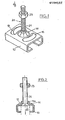
- the anchor rail 10 has conical or crater-shaped formations 11 at regular intervals, which point away from the rail web.
- the formation 11 ends in its upper part in a neck 11a which is essentially cylindrical in shape.
- the inner lateral surface of their formation 11 is shaped so that it provides a secure fit for the head 22 of a countersunk screw 21 which is screwed into an internal thread of the neck 11a.
- the tensile forces or bearing loads that occur are transmitted over a large area through the conical side surfaces of the screw head 22 to the inner lateral surfaces of the formation 11, and evenly on all sides, so that notch stresses are avoided. that can arise with square opening cross-sections.
- Circular arc-shaped beads or ribs 12, 13 are formed on both sides of the formation 11 in the longitudinal direction of the anchor rail 10 and are arranged on a common circle with the center of the formation 11 as the center. These beads are used for Bracing of the rail web in the force introduction areas of the formation 11 into the anchor rail and general stiffening.
- a nut 23 is screwed onto the free end of the shaft 21 pointing away from the rail jerk as an additional anchoring element, the lower ring surface of which forms the saddle surface in the concrete.
- any anchoring element can be used instead of the nut 23, provided that it has a suitable internal thread or only a sufficient bore so that it can be fixed between two nuts.
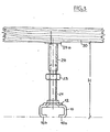
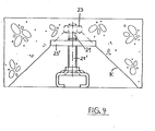
- FIGS 3 and 4 each show an example of the choice of special anchoring elements.
- a spacer sleeve 24 is screwed onto the free end of the screw shaft 21 as a positioning element, the base 24a of which is fixed on the formwork board 30 with a nail.
- a nut 23 in turn serves as an anchoring element.
- the anchor rail can be positioned in a simple manner at a predeterminable height H, which corresponds to the desired concrete thickness. The concrete can then be removed cleanly via the leg surfaces 10a, 10b facing each other.
- FIG. 4 in a modification of FIGS. 2 and 3, an embodiment is shown in which, instead of a long screw 21 with nut 23 as an anchoring element (shown in dashed lines), a shortened screw 21 'with a screwed-on tension distribution plate 23' is used. This is particularly important if only a small concrete thickness is available.
- the two alternatively usable components 21, 23 and 21 ', 23' are dimensioned such that they result in the same tensile load values, which is indicated in a common breakout cone K, in other words, a lower binding depth of the anchoring element can be achieved by a compensate for the corresponding increase in the saddle area of the anchoring element, and vice versa.
- the illustrated exemplary embodiments also show that the combination, for example, of a spacer sleeve and a tension distribution plate on the same screw is possible, the number of combinations is hardly a limit, so the free end of the screw shaft 21 offers a variety of options for the non-positive fastening of additional anchoring elements that can be matched to the respective purpose and location of the anchor channel.
Landscapes
- Engineering & Computer Science (AREA)
- Architecture (AREA)
- Physics & Mathematics (AREA)
- Electromagnetism (AREA)
- Civil Engineering (AREA)
- Structural Engineering (AREA)
- Joining Of Building Structures In Genera (AREA)
- Moving Of Heads (AREA)
- Soil Working Implements (AREA)
- Magnetic Heads (AREA)
- Valve Device For Special Equipments (AREA)
- Surgical Instruments (AREA)
- Medicines That Contain Protein Lipid Enzymes And Other Medicines (AREA)
- Mutual Connection Of Rods And Tubes (AREA)
- Vehicle Body Suspensions (AREA)
- Refuge Islands, Traffic Blockers, Or Guard Fence (AREA)
- Machines For Laying And Maintaining Railways (AREA)
Abstract
Description
- Die Erfindung betrifft eine Ankerschiene für die Bautechnik, mit auf dem Schienensteg angeordneten Ausformungen, in denen Öffnungen vorgesehen sind, die von einem Verankerungsteil hintergriffen sind.
- Eine derartige Ankerschiene ist aus der DE-PS 26 31 396 bekannt. Dort dienen als Verankerungsteile Stücke von T-Profilen, die sich mit Rippen auf den Ausformungen und deren in das Innere der Ankerschiene ragende Ende durch Stauchung mit dem Ankerschienenrücken starr verbunden ist.
- Diese konstruktive Gestaltung ermöglicht zwar eine ausreichende Stabilität, die verwendeten T-Profile mit den angeformten Stützrippen müssen jedoch separat hergestellt werden und in eine geeignete Länge geschnitten werden, damit sie in die Öffnungen auf dem Schienenrücken passen.
- Diese vorbekannten Ankerschienen müssen daher samt diesen Verankerungselementen werkseitig vollständig hergestellt werden, wodurch sich ein ungünstiges Transportvolumen ergibt, für verschiedenartige statische Belastungen und Ankerschiene-Querschnitte müssen entsprechend angepaßte T-Profile mit der speziellen Querschnittgestaltung auf Lager gehalten werden.
- Darüberhinaus ist die Verbindung dieser Verankerungselemente mit zusätzlichen Bauteilen wie Bewehrungen oder Zugverteilerplatten nur durch Anschweißen dieser Bauteile möglich.
- Die einstückige Ausführung des Verankerungselementes und der Zwang zur begrenzten Lagerhaltung nur einiger weniger derartiger Profilstücke erlaubt durch die Auswahl eines der zur Verfugung stehenden Profilstücke nur. eine grobe Anpassung an die im Einzelfall vorliegenden geometrischen und statischen Bedingungen, die ihren Niederschlag in der Einbindetiefe des Verankerungselementes einerseits und der effektiven Tragfläche des Verankerungselementes andererseits finden, wobei letztere bei der vorbekannten Ankerschiene im wesentlichen durch die obere, abschließende Brücke des T-Profils gegeben ist.
- Aufgabe der Erfindung ist es daher, eine derartige Ankerschiene mit Verankerungselementen rationeller herstellbar zu machen, insbesondere ohne Schweißarbeiten, und dabei mit wenigen, einfachen Bauteilen auszukommen, die eine präzise Anpassung auf alle praktisch vorkommenden statischen und geometrischen Erfordernisse beim jeweiligen Bauobjekt sicherstellen.
- Diese Aufgabe wird erfindungsgemäß dadurch gelöst, daß die Ausformungen konusartig ausgebildet sind und in einen Hals auslaufen, dessen Symmetrie-Achse senkrecht zur Längsachse der Ankerschiene steht, und der zur kraftschlüssigen Aufnahme eines Teils des Schaftes einer als Verankerungsteil dienenden Schraube ausgebildet ist, deren Kopf die Ausformung hintergreift, und auf deren Schaft mindestens ein zusätzliches Element zur Verankerung und/oder Positionierung der Ankerschiene aufschraubbar ist.
- Die hierzu erforderliche Ausformung läßt sich im Kaltpreßverfahren ohne Schwierigkeiten herstellen, die Form dieser Ausformung und der Durchmesser des Halses kann ohne weiteres so ausgebildet werden, daß beispielsweise eine übliche Senkkopfschraube dort mit ihrem Kopf einen sicheren Sitz findet, deren freies Ende von der Ankerschiene wegzeigt, und die mit der Innenfläche des Schienensteges bündg abschließt. Der ausgeformte Hals wirkt dabei einerseits als Führungselement für die Schraube und andererseits bewirkt er eine zusätzliche Stabilisierung des Schienensteges.
- Damit ist einerseits erreicht, daß auf spezielle Profile als Verankerungsteile verzichtet werden kann, die Ausformungen mit ihrem Hals müssen lediglich an gängige Schraubentypen angepaßt sein.
- Dies eröffnet die zusätzliche Möglichkeit, auf das freie Ende der Schraube ein beliebiges Verankerungselement aufzuschrauben, dessen Form und die statische Eigenschaften auf den jeweiligen Anwendungsfall genau abgestimmt sein kann. Insbesondere lassen sich bei der erfindungsgemäßen Lösung Einbindetiefe und lastabtragende Fläche unabhängig voneinander wählen, da die Länge der verwendeten Schraube vorgebbar ist und andererseits auch der Abstand des im Einzelfall bevorzugten zusätzlichen Verankerungselementes vom Schienensteg.
- Die erfindungsgemäße Lösung stellt somit im Vergleich zur gattungsgemäßen Ankerschiene einen wesentlichen Schritt in Richtung einer Standardisierung in dem Sinne dar, auf spezielle Bauteile verzichtet werden kann und stattdessen auf Teile zurückgegriffen wird, die bei der Lagerhaltung ohnehin berücksichtigt sind.
- Ein Ausführungsbeispiel der Erfindung ist in den Zeichnungen näher dargestellt, es zeigen:
- Fig. 1: Eine schematische perspektivische Darstellung eines Teils der erfindungsgemäßen Ankerschiene mit dem Verankerungsteil,
- Fig. 2: einen Schnitt senkrecht zur Längsachse der Ankerschiene durch das Verankerungsteil,
- Fig. 3: eine Stirnansicht der am Schalungsbrett befestigten Ankerschiene,
- Fig. 4: eine schematische Schnittdarstellung der eingebauten Ankerschiene.
- Die Ankerschiene 10 weist in regelmäßigen Abständen kegel- oder kraterförmige Ausformungen 11 auf, die vom Schienensteg wegzeigen. Die Ausformung 11 läuft in ihrem oberen Teil in einen Hals lla aus, der im wesentlichen zylindrisch geformt ist. Die innere Mantelfläche dere Ausformung 11 ist so geformt, daß sie einen sicheren Sitz für den Kopf 22 einer Senkkopfschraube 21 bietet, die in ein Innengewinde des Halses 11a eingeschraubt ist. Die auftretenden Zugkräfte bzw. Tragbelastungen werden durch die konusförmigen Seitenflächen des Schraubenkopfes 22 großflächig auf die inneren Mantelflächen der Ausformung 11 übertragen, und zwar gleichmäßig nach allen Seiten, so daß Kerbbeanspruchungen vermieden werden,. die bei eckigen Öffnungsquerschnitten entstehen können.
- Beidseitig der Ausformung 11 in Längsrichtung der Ankerschiene 10 sind kreisbogenförmige Sicken bzw. Rippen 12,13 ausgeformt, die auf einem gemeinsamen Kreis mit dem Mittelpunkt der Ausformung 11 als Mittelpunkt angeordnet sind. Diese Sicken dienen zur Aussteifung des Schienensteges in den Krafteinleitungsbereichen der Ausformung 11 in die Ankerschiene sowie allgemeinen Aussteifung.
- Auf das freie, vom Schienenrucken wegzeigende Ende des Schaftes 21 ist als zusätzliches Verankerungselement eine Mutter 23 aufgeschraubt, deren untere Ringfläche die Aufsattelfläche im Beton bildet.
- Abweichend vom dargestellten Ausführungsbeispiel kann anstelle der Mutter 23 jedes beliebige Verankerungselement verwendet werden, sofern dies ein passendes Innengewinde aufweist oder lediglich eine ausreichende Bohrung, damit es zwischen zwei Muttern festgesetzt werden kann.
- Die Figuren 3 und 4 zeigen je ein Beispiel fUr die Wahl spezieller Verankerungselemente.
- In Figur 3 ist auf das freie Ende des Schraubenschaftes 21 als Positionierungselement eine Distanzhülse 24 aufgeschraubt, deren Fuß 24a auf dem Schalungsbrett 30 mit einem Nagel fixiert ist. Als Verankerungselement dient wiederum eine Mutter 23. Dadurch kann die Ankerschiene auf einfache Weise in einer vorgebbaren Hohe H, die der gewünschten Betonstärke entspricht, positioniert werden. Über die zueinander zeigenden Schenkelflächen 10a,10b kann dann der Beton sauber abgezogen werden.
- In Figur 4 ist in Abwandlung der Figuren 2 und 3 eine Ausführung dargestellt, bei der anstelle einer langen Schraube 21 mit Mutter 23 als Verankerungselement (gestrichelt dargestellt), eine verkürzte Schraube 21' mit einer aufgeschraubten Zugverteilerplatte 23' Verwendung findet. Dies ist insbesondere dann von Bedeutung, wenn nur eine geringe Betondicke zur Verfügung steht. In Figur 4 sind die beiden alternativ einsetzbaren Bauteile 21,23 bzw. 21',23' so dimensioniert, daß sie die gleichen Zugbelastungswerte ergeben, was sich in gemeinsamem Ausbruchkegel K andeutet, mit anderen Worten, eine geringere Einbindetiefe des Verankerungselementes läßt sich durch eine entsprechende Vergrößerung der Aufsattelfläche des Verankerungselementes kompensieren, und umgekehrt.
- Die dargestellten Ausführungsbeispiele lassen auch erkennen, daß die Kombination bspw. einer Distanzhülse und einer Zugverteilerplatte auf derselben Schraube möglich ist, der Anzahl der Kombinationen ist kaum eine Grenze gesetzt, durch das freie Ende des Schraubenschaftes 21 sind also vielfältige Möglichkeiten zur kraftschlüssigen Befestigung zusätzlicher Verankerungselemente gegeben, die auf den jeweiligen Verwendungszweck und Einsatzort der Ankerschiene abgestimmt sein können.
- Die großflächige, sich an den Verlauf des Schraubenkopfes anschmiegende Innenwandung der Ausformung 11 führt zu einer schonenden Krafteinleitung in die Ankerschiene, die sich in hervorragenden Zugbelastungswerten ausdrückt, die bei Anbringung der Rippen noch verbessert werden können.
Claims (9)
Priority Applications (1)
| Application Number | Priority Date | Filing Date | Title |
|---|---|---|---|
| AT85100888T ATE59870T1 (de) | 1984-03-02 | 1985-01-29 | Ankerschiene. |
Applications Claiming Priority (2)
| Application Number | Priority Date | Filing Date | Title |
|---|---|---|---|
| DE3407801A DE3407801C1 (de) | 1984-03-02 | 1984-03-02 | Ankerschiene |
| DE3407801 | 1984-03-02 |
Publications (3)
| Publication Number | Publication Date |
|---|---|
| EP0154157A2 true EP0154157A2 (de) | 1985-09-11 |
| EP0154157A3 EP0154157A3 (en) | 1988-03-23 |
| EP0154157B1 EP0154157B1 (de) | 1991-01-09 |
Family
ID=6229468
Family Applications (1)
| Application Number | Title | Priority Date | Filing Date |
|---|---|---|---|
| EP85100888A Expired - Lifetime EP0154157B1 (de) | 1984-03-02 | 1985-01-29 | Ankerschiene |
Country Status (9)
| Country | Link |
|---|---|
| US (1) | US4571912A (de) |
| EP (1) | EP0154157B1 (de) |
| JP (1) | JPH063052B2 (de) |
| KR (1) | KR930011534B1 (de) |
| AT (1) | ATE59870T1 (de) |
| AU (1) | AU577834B2 (de) |
| CA (1) | CA1235587A (de) |
| DE (2) | DE3407801C1 (de) |
| ES (1) | ES296251Y (de) |
Cited By (3)
| Publication number | Priority date | Publication date | Assignee | Title |
|---|---|---|---|---|
| EP0619402A3 (de) * | 1993-04-08 | 1995-03-29 | Halfen Gmbh & Co Kg | Anker für Ankerschienen für die Bautechnik. |
| EP1067248A2 (de) | 1999-07-08 | 2001-01-10 | Sergio Zambelli | Verankerungsvorrichtung für Betonbauteile oder ähnliches mit einem einfach zu benutzendem Element zum Verankern an dem Bauteil |
| US20230052828A1 (en) * | 2020-01-22 | 2023-02-16 | Fischerwerke Gmbh & Co. Kg | Anchor channel and method for producing an anchor channel |
Families Citing this family (26)
| Publication number | Priority date | Publication date | Assignee | Title |
|---|---|---|---|---|
| DE3531998A1 (de) * | 1985-09-07 | 1987-03-19 | Halfeneisen Gmbh & Co Kg | In beton oder dergleichen einbettbare ankerschiene |
| DE3546107A1 (de) * | 1985-12-24 | 1987-06-25 | Halfeneisen Gmbh & Co Kg | Ankerschiene fuer bautechnik |
| JPS63155572A (ja) * | 1986-12-12 | 1988-06-28 | アンプ インコ−ポレ−テツド | シ−ルドコネクタ |
| US5039006A (en) * | 1989-08-16 | 1991-08-13 | Habegger Millard A | Home heating system draft controller |
| DE4228463C2 (de) * | 1992-08-27 | 2001-07-26 | Halfen Gmbh & Co Kg | Verfahren zur Herstellung einer Ankerschiene für die Bautechnik und Vorrichtung zur Durchführung des Verfahrens |
| DE4326322C2 (de) * | 1993-08-05 | 2003-01-09 | Halfen Gmbh & Co Kg | Ankerschiene für die Bautechnik |
| US5743062A (en) * | 1994-02-15 | 1998-04-28 | Halfen Gmbh & Co. Kommanditgesellschaft | Anchoring device for housing/building construction |
| DE29903167U1 (de) * | 1999-02-16 | 1999-05-27 | Deutsche Kahneisen Gesellschaft mbH, 12057 Berlin | Ankerschiene mit schieneninnenseitig einsehbarer Kennzeichnung |
| US6820390B2 (en) * | 2001-02-06 | 2004-11-23 | Todd M. Schulze | Weldment plate spacer support |
| US20060185282A1 (en) * | 2001-02-06 | 2006-08-24 | Schulze Todd M | Weldment plate stud extender support |
| US20060123726A1 (en) * | 2004-12-10 | 2006-06-15 | Michael Azarin | Channel anchor |
| CN1869355A (zh) * | 2005-05-23 | 2006-11-29 | 亚洲研制有限公司 | 混凝土用热轧钢制预埋连接件 |
| KR100668112B1 (ko) * | 2005-08-05 | 2007-01-11 | 알루텍 (주) | 콘크리트 구조물에 매입되는 조립형 채널 |
| CN101387130A (zh) * | 2007-09-11 | 2009-03-18 | 游柏森 | 建筑工业用槽件锚固装置 |
| KR100978410B1 (ko) * | 2007-10-29 | 2010-08-26 | 현대엔지니어링 주식회사 | 2차부재 고정용 매입기구 |
| US8220845B2 (en) * | 2008-03-14 | 2012-07-17 | Mallory Curtis G | Exhaust manifold clamp apparatus |
| USD651324S1 (en) | 2008-05-07 | 2011-12-27 | Bai Sen You | Channel |
| DE102008054799A1 (de) * | 2008-12-17 | 2010-06-24 | Hilti Aktiengesellschaft | Ankerschiene |
| DE102008054807A1 (de) * | 2008-12-17 | 2010-06-24 | Hilti Aktiengesellschaft | Ankerschiene |
| KR101302458B1 (ko) * | 2012-10-11 | 2013-09-02 | 이재호 | 서브 앵커를 갖는 선시공 앵커 채널 |
| CN104631627A (zh) * | 2013-11-13 | 2015-05-20 | 山东天工岩土工程设备有限公司 | 一种新型带齿预埋槽道 |
| EP3081708B1 (de) * | 2015-04-18 | 2020-09-02 | HALFEN GmbH | Ankerschiene zur verankerung im beton |
| ES2657318B1 (es) * | 2016-09-02 | 2018-10-29 | R.C.P. Industriales, S.L. | Anclaje para paneles de cerramiento de estructuras arquitectónicas |
| CN106759937A (zh) * | 2016-12-14 | 2017-05-31 | 刘志林 | 一种可替换调节的金属滑槽预埋件 |
| US11680400B2 (en) | 2018-05-18 | 2023-06-20 | Cetres Holdings, Llc | Concrete boss anchor |
| USD936470S1 (en) * | 2019-05-29 | 2021-11-23 | Gareth William Menzies as trustee for GM TRUST & SWM TRUST & RGM TRUST | Fastener |
Family Cites Families (11)
| Publication number | Priority date | Publication date | Assignee | Title |
|---|---|---|---|---|
| US992877A (en) * | 1909-08-27 | 1911-05-23 | Trussed Concrete Steel Co | Shaft-hanger support. |
| FR467589A (fr) * | 1913-01-24 | 1914-06-15 | Bruno Bauer | Mode de construction en béton armé |
| US1155243A (en) * | 1914-07-02 | 1915-09-28 | Anders Jordahl | Means for suspending objects from reinforced concrete structures. |
| US2299158A (en) * | 1941-02-18 | 1942-10-20 | Richard W Luce | Gang channel fastener |
| US3208409A (en) * | 1964-05-25 | 1965-09-28 | John Gale Company | Desk device |
| US3391514A (en) * | 1966-06-13 | 1968-07-09 | Structural Fasteners Inc | Structural fasteners |
| DE2534908A1 (de) * | 1975-08-01 | 1977-02-03 | Harald Papke | Vorrichtung zur befestigung von lasten an stahlbetonbauwerken |
| DE2619182A1 (de) * | 1976-04-30 | 1977-11-17 | Modersohn Gmbh & Co Kg Wilh | Ankerschiene, anschweissplatte o.dgl. mit einem anschweisstueck |
| DE2631396C2 (de) * | 1976-07-13 | 1978-02-16 | Beine, Karlheinz, Dipl.-Ing, 4030 Ratingen | In ein Bauteil einbettbare Ankerschiene mit Verankerungselementen |
| US4396326A (en) * | 1980-10-30 | 1983-08-02 | Ford Motor Company | Self sealing J nut |
| US4534145A (en) * | 1983-07-25 | 1985-08-13 | The Firestone Tire & Rubber Company | Attachment device for securing flexible sheets |
-
1984
- 1984-03-02 DE DE3407801A patent/DE3407801C1/de not_active Expired
-
1985
- 1985-01-29 EP EP85100888A patent/EP0154157B1/de not_active Expired - Lifetime
- 1985-01-29 AT AT85100888T patent/ATE59870T1/de not_active IP Right Cessation
- 1985-01-29 DE DE8585100888T patent/DE3581219D1/de not_active Expired - Lifetime
- 1985-03-01 CA CA000475598A patent/CA1235587A/en not_active Expired
- 1985-03-01 ES ES1985296251U patent/ES296251Y/es not_active Expired
- 1985-03-01 JP JP60038984A patent/JPH063052B2/ja not_active Expired - Fee Related
- 1985-03-02 KR KR1019850001312A patent/KR930011534B1/ko not_active Expired - Fee Related
- 1985-03-04 US US06/707,512 patent/US4571912A/en not_active Expired - Lifetime
- 1985-03-04 AU AU39464/85A patent/AU577834B2/en not_active Ceased
Cited By (3)
| Publication number | Priority date | Publication date | Assignee | Title |
|---|---|---|---|---|
| EP0619402A3 (de) * | 1993-04-08 | 1995-03-29 | Halfen Gmbh & Co Kg | Anker für Ankerschienen für die Bautechnik. |
| EP1067248A2 (de) | 1999-07-08 | 2001-01-10 | Sergio Zambelli | Verankerungsvorrichtung für Betonbauteile oder ähnliches mit einem einfach zu benutzendem Element zum Verankern an dem Bauteil |
| US20230052828A1 (en) * | 2020-01-22 | 2023-02-16 | Fischerwerke Gmbh & Co. Kg | Anchor channel and method for producing an anchor channel |
Also Published As
| Publication number | Publication date |
|---|---|
| AU577834B2 (en) | 1988-10-06 |
| EP0154157B1 (de) | 1991-01-09 |
| ES296251Y (es) | 1988-03-16 |
| JPS60226928A (ja) | 1985-11-12 |
| ES296251U (es) | 1987-08-16 |
| US4571912A (en) | 1986-02-25 |
| CA1235587A (en) | 1988-04-26 |
| ATE59870T1 (de) | 1991-01-15 |
| KR850006723A (ko) | 1985-10-16 |
| DE3581219D1 (de) | 1991-02-14 |
| KR930011534B1 (ko) | 1993-12-10 |
| DE3407801C1 (de) | 1985-06-20 |
| EP0154157A3 (en) | 1988-03-23 |
| AU3946485A (en) | 1985-09-05 |
| JPH063052B2 (ja) | 1994-01-12 |
Similar Documents
| Publication | Publication Date | Title |
|---|---|---|
| EP0154157B1 (de) | Ankerschiene | |
| DE1955955C3 (de) | ||
| EP0292742A1 (de) | Distanzschraube | |
| EP2993279B1 (de) | Bauwerk mit einem Verstärkungselement aus hochfestem Beton zur Erhöhung der Durchstanzfestigkeit | |
| EP0328484A1 (de) | Gleithülse zur Aufnahme eines Querkraftdornes | |
| DE2812502C2 (de) | ||
| DE4429813C2 (de) | Nivellierschuh | |
| EP3047159B1 (de) | Profilverbinder sowie profilverbund | |
| DD211607A5 (de) | Selbstschneidender gewindeeinsatz | |
| DE69524377T2 (de) | Verbindungs- oder Verankerungsvorrichtung von Bewehrungsstäben hoher Haftung im Stahlbeton und Verfahren zu ihrer Realisierung | |
| DD232813A5 (de) | Befestigungsplatte oder dergleichen fuer moebelbeschlagteile | |
| DE69006308T2 (de) | Stütz- und Verankerungsvorrichtung für vorgefertigte, insbesondere aus Beton oder ähnlichem hergestellte Gebäudeteile. | |
| EP1247922B1 (de) | Bodenstütze mit einer Kopfplatte zum Abstützen eines Doppelbodenaufbaus sowie Doppelbodenaufbau | |
| DE29618158U1 (de) | Abstandhalter | |
| EP0158944A2 (de) | Transportanker für das Anschlagen von Stahlbetonfertigteilen an ein Hebezeug | |
| DE3842229A1 (de) | Justierbares kopfplatten - zwischenbauteil | |
| WO1997001008A1 (de) | Einrichtung zur festlegung von bewehrungen | |
| EP0493681B1 (de) | Vorrichtung zum Verankern von Wandplatten an einem Verankerungsgrund | |
| EP0167106A2 (de) | Hohldübel für den Eisenbahnbau | |
| DE3918044A1 (de) | Ankerschiene fuer die bautechnik | |
| EP0686736B1 (de) | Verfahren und Vorrichtung zum Befestigen von Halterungen an den Stirnseiten von Betonplatten oder Betonscheiben | |
| EP3348742A1 (de) | Abstützvorrichtung zur abstützung einer fassadenplatte an einer tragstruktur | |
| EP0502266A1 (de) | Gerüstsystem | |
| EP3375947B1 (de) | Verbinder zum schrägverschrauben zweier werkstücke | |
| DE8536514U1 (de) | Ankerschiene für Bautechnik |
Legal Events
| Date | Code | Title | Description |
|---|---|---|---|
| PUAI | Public reference made under article 153(3) epc to a published international application that has entered the european phase |
Free format text: ORIGINAL CODE: 0009012 |
|
| AK | Designated contracting states |
Designated state(s): AT BE CH DE FR GB IT LI LU NL SE |
|
| PUAL | Search report despatched |
Free format text: ORIGINAL CODE: 0009013 |
|
| AK | Designated contracting states |
Kind code of ref document: A3 Designated state(s): AT BE CH DE FR GB IT LI LU NL SE |
|
| 17P | Request for examination filed |
Effective date: 19880910 |
|
| 17Q | First examination report despatched |
Effective date: 19891124 |
|
| DIN1 | Information on inventor provided before grant (deleted) | ||
| RAP1 | Party data changed (applicant data changed or rights of an application transferred) |
Owner name: UNISTRUT EUROPE PLC |
|
| GRAA | (expected) grant |
Free format text: ORIGINAL CODE: 0009210 |
|
| AK | Designated contracting states |
Kind code of ref document: B1 Designated state(s): AT BE CH DE FR GB IT LI LU NL SE |
|
| REF | Corresponds to: |
Ref document number: 59870 Country of ref document: AT Date of ref document: 19910115 Kind code of ref document: T |
|
| REF | Corresponds to: |
Ref document number: 3581219 Country of ref document: DE Date of ref document: 19910214 |
|
| ET | Fr: translation filed | ||
| GBT | Gb: translation of ep patent filed (gb section 77(6)(a)/1977) | ||
| ITF | It: translation for a ep patent filed | ||
| PLBE | No opposition filed within time limit |
Free format text: ORIGINAL CODE: 0009261 |
|
| STAA | Information on the status of an ep patent application or granted ep patent |
Free format text: STATUS: NO OPPOSITION FILED WITHIN TIME LIMIT |
|
| 26N | No opposition filed | ||
| EPTA | Lu: last paid annual fee | ||
| EAL | Se: european patent in force in sweden |
Ref document number: 85100888.8 |
|
| NLS | Nl: assignments of ep-patents |
Owner name: HALFEN GMBH & CO. KOMMANDITGESELLSCHAFT |
|
| NLT1 | Nl: modifications of names registered in virtue of documents presented to the patent office pursuant to art. 16 a, paragraph 1 |
Owner name: UNISTRUT EUROPE LIMITED |
|
| REG | Reference to a national code |
Ref country code: CH Ref legal event code: PUE Owner name: UNISTRUT EUROPE LIMITED TRANSFER- HALFEN GMBH & CO Ref country code: CH Ref legal event code: PFA Free format text: UNISTRUT EUROPE PLC TRANSFER- UNISTRUT EUROPE LIMITED |
|
| REG | Reference to a national code |
Ref country code: FR Ref legal event code: TP Ref country code: FR Ref legal event code: CJ |
|
| REG | Reference to a national code |
Ref country code: GB Ref legal event code: 732E |
|
| BECA | Be: change of holder's address |
Free format text: 960606 *HALFEN G.M.B.H. & CO. K.G.:HARFFSTRASSE 47-51, D-40591 DUESSELDORF |
|
| BECH | Be: change of holder |
Free format text: 960606 *HALFEN G.M.B.H. & CO. K.G. |
|
| REG | Reference to a national code |
Ref country code: GB Ref legal event code: IF02 |
|
| PGFP | Annual fee paid to national office [announced via postgrant information from national office to epo] |
Ref country code: CH Payment date: 20021218 Year of fee payment: 19 |
|
| PGFP | Annual fee paid to national office [announced via postgrant information from national office to epo] |
Ref country code: NL Payment date: 20021227 Year of fee payment: 19 Ref country code: GB Payment date: 20021227 Year of fee payment: 19 |
|
| PGFP | Annual fee paid to national office [announced via postgrant information from national office to epo] |
Ref country code: LU Payment date: 20021230 Year of fee payment: 19 |
|
| PGFP | Annual fee paid to national office [announced via postgrant information from national office to epo] |
Ref country code: AT Payment date: 20030102 Year of fee payment: 19 |
|
| PGFP | Annual fee paid to national office [announced via postgrant information from national office to epo] |
Ref country code: SE Payment date: 20030109 Year of fee payment: 19 |
|
| PGFP | Annual fee paid to national office [announced via postgrant information from national office to epo] |
Ref country code: FR Payment date: 20030110 Year of fee payment: 19 |
|
| PGFP | Annual fee paid to national office [announced via postgrant information from national office to epo] |
Ref country code: BE Payment date: 20030122 Year of fee payment: 19 |
|
| PGFP | Annual fee paid to national office [announced via postgrant information from national office to epo] |
Ref country code: DE Payment date: 20030124 Year of fee payment: 19 |
|
| PG25 | Lapsed in a contracting state [announced via postgrant information from national office to epo] |
Ref country code: LU Free format text: LAPSE BECAUSE OF NON-PAYMENT OF DUE FEES Effective date: 20040129 Ref country code: GB Free format text: LAPSE BECAUSE OF NON-PAYMENT OF DUE FEES Effective date: 20040129 Ref country code: AT Free format text: LAPSE BECAUSE OF NON-PAYMENT OF DUE FEES Effective date: 20040129 |
|
| PG25 | Lapsed in a contracting state [announced via postgrant information from national office to epo] |
Ref country code: SE Free format text: LAPSE BECAUSE OF NON-PAYMENT OF DUE FEES Effective date: 20040130 |
|
| PG25 | Lapsed in a contracting state [announced via postgrant information from national office to epo] |
Ref country code: LI Free format text: LAPSE BECAUSE OF NON-PAYMENT OF DUE FEES Effective date: 20040131 Ref country code: CH Free format text: LAPSE BECAUSE OF NON-PAYMENT OF DUE FEES Effective date: 20040131 Ref country code: BE Free format text: LAPSE BECAUSE OF NON-PAYMENT OF DUE FEES Effective date: 20040131 |
|
| BERE | Be: lapsed |
Owner name: *HALFEN G.M.B.H. & CO. K.G. Effective date: 20040131 |
|
| PG25 | Lapsed in a contracting state [announced via postgrant information from national office to epo] |
Ref country code: NL Free format text: LAPSE BECAUSE OF NON-PAYMENT OF DUE FEES Effective date: 20040801 |
|
| PG25 | Lapsed in a contracting state [announced via postgrant information from national office to epo] |
Ref country code: DE Free format text: LAPSE BECAUSE OF NON-PAYMENT OF DUE FEES Effective date: 20040803 |
|
| EUG | Se: european patent has lapsed | ||
| GBPC | Gb: european patent ceased through non-payment of renewal fee |
Effective date: 20040129 |
|
| REG | Reference to a national code |
Ref country code: CH Ref legal event code: PL |
|
| PG25 | Lapsed in a contracting state [announced via postgrant information from national office to epo] |
Ref country code: FR Free format text: LAPSE BECAUSE OF NON-PAYMENT OF DUE FEES Effective date: 20040930 |
|
| NLV4 | Nl: lapsed or anulled due to non-payment of the annual fee |
Effective date: 20040801 |
|
| REG | Reference to a national code |
Ref country code: FR Ref legal event code: ST |