EP0154309A2 - Réservoir d'égalisation de pression - Google Patents
Réservoir d'égalisation de pression Download PDFInfo
- Publication number
- EP0154309A2 EP0154309A2 EP85102313A EP85102313A EP0154309A2 EP 0154309 A2 EP0154309 A2 EP 0154309A2 EP 85102313 A EP85102313 A EP 85102313A EP 85102313 A EP85102313 A EP 85102313A EP 0154309 A2 EP0154309 A2 EP 0154309A2
- Authority
- EP
- European Patent Office
- Prior art keywords
- container
- membrane
- tank according
- tension member
- opening
- Prior art date
- Legal status (The legal status is an assumption and is not a legal conclusion. Google has not performed a legal analysis and makes no representation as to the accuracy of the status listed.)
- Withdrawn
Links
Images
Classifications
-
- F—MECHANICAL ENGINEERING; LIGHTING; HEATING; WEAPONS; BLASTING
- F24—HEATING; RANGES; VENTILATING
- F24D—DOMESTIC- OR SPACE-HEATING SYSTEMS, e.g. CENTRAL HEATING SYSTEMS; DOMESTIC HOT-WATER SUPPLY SYSTEMS; ELEMENTS OR COMPONENTS THEREFOR
- F24D3/00—Hot-water central heating systems
- F24D3/10—Feed-line arrangements, e.g. providing for heat-accumulator tanks, expansion tanks ; Hydraulic components of a central heating system
- F24D3/1008—Feed-line arrangements, e.g. providing for heat-accumulator tanks, expansion tanks ; Hydraulic components of a central heating system expansion tanks
Definitions
- the invention relates to a surge tank of the type corresponding to the preamble of claim 1.
- Such surge tanks in the form of cylindrical, upright boilers are known in which the membrane space occupies approximately the lower half of the interior of the tank.
- the membrane is made of rubber and is inserted into the container from below through the feed opening during assembly and after the inspections required at regular intervals or when it is renewed in a rolled-up state.
- the sack-like membrane When the sack-like membrane is filled with liquid, ie mostly with water, the membrane unfolds until it finally fills the membrane space. So that the membrane is not overstretched, a perforated intermediate floor is drawn into the container to delimit the membrane space, against which the top side of the membrane can lie with the utmost filling.
- the surge tank must be flipped for this purpose, so that the insertion of the relatively long rod through the feed opening, which is located close to the ground, is possible, or it must be telescopic or consisting of several sections and each to be assembled during assembly Poles can be used.
- the invention has for its object to simplify the determination of the inner end of the membrane.
- the design of the bracket as a tension member is a simplification, because the stress on the train does not require any particular stiffness, as is the case with a longer rod that is subjected to pressure.
- the tension member in the invention remains in the gas space of the container and need not be inserted into it from the outside. In this way, repositioning the container or complicated configurations of the holders are unnecessary.
- the tension member is actuated from the inside of the container, for example by a winch attached there.
- the tension member is operated relatively rarely, the effort involved can be too high.
- the tension member is a rod (claim 3).
- the guide can be designed in detail according to claims 5 or 6.
- the fastening attachment of the membrane, on which the tensile force of the tension member acts can be designed according to claim 7.
- the embodiment of claim 9 is also to be seen from this aspect. If the shape of the membrane corresponds to the membrane space delimited by the container and the intermediate floor, with the membrane filled, practically no force is exerted on the membrane by the weight of the liquid, which contributes to avoiding forces within the membrane and to extending its life .
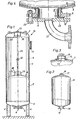
- the pressure equalization tank designated as a whole in FIG. 1 comprises a cylindrical tank-shaped tank 1 with bottoms 2 and 3 of circular cross-section.
- the container 1 stands on three supports 4 distributed over the circumference and has in the middle of its underside an access opening 6 provided with a flange 5, through which the liquid, the volume of which changes and the pressure of which is to be compensated, from below into the The lower area of the container 1 provided membrane space 7 can be initiated.
- the membrane space 7 is delimited at the top by a perforated intermediate floor 8 which is fastened to the inner circumference of the container 1.
- the remaining interior of the container 1 above the intermediate floor 8 is the gas space 9, which is filled with nitrogen to a predetermined pressure by means of a gas filling valve 12.
- the flange 11 serves as a viewing flange, designed in accordance with AD information sheet A5 (prepared by the Pressure Vessel Working Group, published by the Association of Technical Supervision Associations, Essen). Depending on the size of the container 1, the flange 11 is attached to the jacket or bottom.
- FIG. 1 In the middle of the upper floor 2 is one in Fig. 1 open mounting opening 13 is provided, the design of which can be found in detail in FIG. 3.
- a threaded connector 14 is welded into the opening of the upper base 2, into which a pressure-tight threaded plug 15 can be screwed when the assembly opening 13 is to be closed.
- the flange 11 In the case of smaller containers, that is to say if the flange 11 is arranged in the upper base 2, the flange 11 can also form the assembly opening.
- the so-called membrane 16 which consists of a bag-like rubber container which can be collapsed and rolled up in a non-pressurized state and in the completely filled state has the kettle-shaped shape with circular cross section shown in Fig. 2. This shape corresponds to the shape of the membrane space 7 in the container 1.
- a stable tab 17 with one or more bores 18 vulcanized or glued as a fastening attachment is such that 17 forces can be introduced through the tab and distributed to the material of the membrane.
- a flange 19 is also vulcanized or glued from rubber or another flexible material, which surrounds the access opening 6 'of the membrane 16.
- FIG. 1 the access opening 6 is shown open and the membrane 16 shown in FIG. 2 has not yet been inserted into the membrane space 7.
- FIG. 4 shows the area of the access opening 6 with the membrane 16 inserted into the membrane space 7.
- the flange 19 of the membrane 16 encompasses the access opening 6 of the flange 5 from the inside. From the outside, another flange 20 with a pipe bend for connecting the feed line for the liquid is attached, which is connected to the flange 5 by screws 22.
- the seal between the flanges 5, 20 forms the encompassing part 19 'of the flange 19th
- the membrane 16 in the membrane space 7 of the container 1 In order to introduce the membrane 16 into the membrane space 7 of the container 1, it is rolled up and inserted from below through the access opening 6 into the membrane space 7. So that the membrane 16 in the membrane space 7, in which it would lie in folds due to its lack of dimensional stability, does not experience any greater forces when filled with liquid, that is to say if the folds are smoothed, and there is also no risk of breakage due to excessive fold formation, the membrane is fixed at its end inside the container in the area of the intermediate floor, so that it is already stretched and no more irregular wrinkling occurs, which reduces the stress during filling.
- the inner end of the membrane is fixed by means of a pull rod 25 which is located in the center of the container 1 from the intermediate floor 8 to the vicinity of the upper end of the container 1, i.e. extends in the vicinity of the mounting opening 13.
- an opening 26 is provided in the intermediate floor 8, through which the pull rod 25 can step down. It has at its lower end a fork-shaped fastening piece 27, the two legs of which are angled outwards at the ends in the manner shown in FIG. 1 and form a stop which limits the path of the pull rod 25 upwards.
- the tab 17 of the membrane 16 is inserted between the legs of the fork-shaped fastening piece 27 and fastened there by one or two screws with washers and nuts.
- a U-shaped bracket 28 fastened on the upper side of the intermediate base 8 is used to guide the pull rod 25 and has a recess in its web for the passage of the pull rod 25. In this way, the pull rod and thus also the upper end of the membrane 16 is guided centrally to the container 1.
- a U-shaped bracket 29 is also fastened under the mounting opening 13 and has its legs pointing upward and is welded to the inside of the base 2.
- a recess is provided in its web, through which the threaded end of the pull rod 25 extends and is locked in the raised state shown in FIG. 1 by a nut 30.
- the nut 30 When the membrane 16 is introduced into the membrane space 7, the nut 30 is loosened through the assembly or inspection opening 13 and the pull rod is connected at the upper end with a rope. The pull rod 25 on the rope is then lowered until its lower end with the fork-shaped fastening piece 27 comes out of the access opening 6. The tab 17 of the membrane 16 is then attached to the fastening piece 27. The membrane is then rolled up and pulled up in this state by means of the pull rod 25 until the angled ends of the legs of the fastening piece 27 rest against the intermediate floor 8 from below and the upper end of the pull rod 25 engages through the recess in the U-shaped bracket 29. Then the nut 30 is screwed, causing the train rod 25 is fixed in the upper position.
- the flange 19 is then brought into position with the membrane 16 and the flange 20 is screwed on from the outside and connected to the liquid supply line.
- the gas space 9 can be filled with gas via the gas filling valve 12.
- the liquid entering the membrane 16 into the membrane space 7 counteracts the pressure of the gas present in the gas space 9, which also communicates to the membrane space 7 through the perforations of the intermediate floor 8.
Landscapes
- Engineering & Computer Science (AREA)
- Physics & Mathematics (AREA)
- Thermal Sciences (AREA)
- Chemical & Material Sciences (AREA)
- Combustion & Propulsion (AREA)
- Mechanical Engineering (AREA)
- General Engineering & Computer Science (AREA)
- Filling Or Discharging Of Gas Storage Vessels (AREA)
- Bag Frames (AREA)
- Buffer Packaging (AREA)
Applications Claiming Priority (2)
| Application Number | Priority Date | Filing Date | Title |
|---|---|---|---|
| DE3408580 | 1984-03-09 | ||
| DE19843408580 DE3408580A1 (de) | 1984-03-09 | 1984-03-09 | Druckausgleichsbehaelter |
Publications (2)
| Publication Number | Publication Date |
|---|---|
| EP0154309A2 true EP0154309A2 (fr) | 1985-09-11 |
| EP0154309A3 EP0154309A3 (fr) | 1987-04-01 |
Family
ID=6229956
Family Applications (1)
| Application Number | Title | Priority Date | Filing Date |
|---|---|---|---|
| EP85102313A Withdrawn EP0154309A3 (fr) | 1984-03-09 | 1985-03-01 | Réservoir d'égalisation de pression |
Country Status (2)
| Country | Link |
|---|---|
| EP (1) | EP0154309A3 (fr) |
| DE (1) | DE3408580A1 (fr) |
Cited By (1)
| Publication number | Priority date | Publication date | Assignee | Title |
|---|---|---|---|---|
| FR2706241A1 (fr) * | 1993-06-09 | 1994-12-23 | Boudault Patrick | Procédé de distribution d'eau à partir d'une réserve, notamment pour l'arrosage de plantes, réserve correspondante, et structure formant jardinière verticale mettant en Óoeuvre ce procédé. |
Family Cites Families (5)
| Publication number | Priority date | Publication date | Assignee | Title |
|---|---|---|---|---|
| US2317395A (en) * | 1938-05-31 | 1943-04-27 | Mercier Jean | Deformable or elastic accumulator |
| DE2111488B1 (de) * | 1971-03-10 | 1972-08-24 | Otto Geb Kg | Druckausdehnungsgefaess fuer Warmwasserheizungen |
| GB1373013A (en) * | 1972-03-06 | 1974-11-06 | Miles D | Expansion compensating means for heating systems |
| JPS55119202A (en) * | 1979-03-05 | 1980-09-12 | Hitachi Ltd | Pressure vessel |
| DE2911303C2 (de) * | 1979-03-22 | 1982-10-28 | Gebr. Otto Kg, 5910 Kreuztal | Druckbehälter für Druckerhöhungsanlagen von Trinkwasserversorgungsanlagen |
-
1984
- 1984-03-09 DE DE19843408580 patent/DE3408580A1/de not_active Withdrawn
-
1985
- 1985-03-01 EP EP85102313A patent/EP0154309A3/fr not_active Withdrawn
Cited By (1)
| Publication number | Priority date | Publication date | Assignee | Title |
|---|---|---|---|---|
| FR2706241A1 (fr) * | 1993-06-09 | 1994-12-23 | Boudault Patrick | Procédé de distribution d'eau à partir d'une réserve, notamment pour l'arrosage de plantes, réserve correspondante, et structure formant jardinière verticale mettant en Óoeuvre ce procédé. |
Also Published As
| Publication number | Publication date |
|---|---|
| EP0154309A3 (fr) | 1987-04-01 |
| DE3408580A1 (de) | 1985-09-12 |
Similar Documents
| Publication | Publication Date | Title |
|---|---|---|
| EP0068473A1 (fr) | Réservoir pour fluide sous pression | |
| CH442413A (de) | Einrichtung an Schienenfahrzeugen zur Abstützung des Fahrzeugoberteils auf den Radgestellen | |
| DE102004060591B4 (de) | Tank für kryogene Medien sowie Verfahren und Vorrichtung zu dessen Zusammenbau | |
| EP1067326B1 (fr) | Réservoir sous pression | |
| DE102016123983A1 (de) | Zugdeichsel für einen Fahrzeuganhänger | |
| DE19510360C2 (de) | Druckausgleichsgefäß | |
| EP3121826B1 (fr) | Dispositif de rêception destinê à recevoir un liquide isolant | |
| DE3408580A1 (de) | Druckausgleichsbehaelter | |
| DE8407202U1 (de) | Druckausgleichsbehaelter | |
| DE102011122215B4 (de) | Kraftstoffbehälter für ein Kraftfahrzeug mit anpassbarem Füllvolumen | |
| EP3121090B1 (fr) | Systeme d'amortisseur pneumatique pour vehicule sur rails et vehicule sur rails comprenant un systeme d'amortisseur pneumatique | |
| EP4386149A1 (fr) | Cadre de fer encastrable pour un réservoir de chasse d'eau dissimulé | |
| DE2606582B1 (de) | Silo | |
| DE19720987C2 (de) | Ausdehnungsgefäß mit Membrane | |
| DE2146370C3 (de) | Ventileinrichtung zum Füllen von Flaschen mit Getränken | |
| DE3411491A1 (de) | Transport- und displaybehaelter | |
| DE19532249C2 (de) | Mobiler Zwischenlagerbehälter für Flüssigkeiten | |
| DE1627823C3 (de) | Hydropneumatischer Druckspeicher | |
| DE2719604C3 (de) | Tank für flüssiges Treibgas, insbesondere für Kraftfahrzeuge | |
| DE3501441A1 (de) | Druckerzeugungssystem fuer verneblungs- oder spruehbehaelter | |
| CH482597A (de) | Batterietank für Flüssigkeiten, insbesondere für Heizöl | |
| DE199234C (fr) | ||
| DE1775977A1 (de) | Druckgefaess | |
| DE1926354A1 (de) | Druckbehaelter | |
| AT249590B (de) | Lagerung für insbesondere zylindrische Lagerbehälter |
Legal Events
| Date | Code | Title | Description |
|---|---|---|---|
| PUAI | Public reference made under article 153(3) epc to a published international application that has entered the european phase |
Free format text: ORIGINAL CODE: 0009012 |
|
| AK | Designated contracting states |
Designated state(s): AT BE CH DE FR GB IT LI LU NL SE |
|
| PUAL | Search report despatched |
Free format text: ORIGINAL CODE: 0009013 |
|
| AK | Designated contracting states |
Kind code of ref document: A3 Designated state(s): AT BE CH DE FR GB IT LI LU NL SE |
|
| STAA | Information on the status of an ep patent application or granted ep patent |
Free format text: STATUS: THE APPLICATION IS DEEMED TO BE WITHDRAWN |
|
| 18D | Application deemed to be withdrawn |
Effective date: 19871002 |
|
| RIN1 | Information on inventor provided before grant (corrected) |
Inventor name: GEBHARDT, HEINRICH Inventor name: KRAEMER, KLAUS |