EP0154390B1 - Assemblages d'épingles pour étiquettes et son procédé de fabrication - Google Patents
Assemblages d'épingles pour étiquettes et son procédé de fabrication Download PDFInfo
- Publication number
- EP0154390B1 EP0154390B1 EP85300317A EP85300317A EP0154390B1 EP 0154390 B1 EP0154390 B1 EP 0154390B1 EP 85300317 A EP85300317 A EP 85300317A EP 85300317 A EP85300317 A EP 85300317A EP 0154390 B1 EP0154390 B1 EP 0154390B1
- Authority
- EP
- European Patent Office
- Prior art keywords
- tag
- fastener assembly
- tag pin
- pins
- connecting rod
- Prior art date
- Legal status (The legal status is an assumption and is not a legal conclusion. Google has not performed a legal analysis and makes no representation as to the accuracy of the status listed.)
- Expired - Lifetime
Links
- 238000000034 method Methods 0.000 title description 15
- 210000003739 neck Anatomy 0.000 claims description 27
- 230000008878 coupling Effects 0.000 claims description 11
- 238000010168 coupling process Methods 0.000 claims description 11
- 238000005859 coupling reaction Methods 0.000 claims description 11
- 238000000465 moulding Methods 0.000 claims description 5
- 239000000853 adhesive Substances 0.000 claims description 3
- 230000001070 adhesive effect Effects 0.000 claims description 3
- 230000004927 fusion Effects 0.000 claims description 3
- 238000004519 manufacturing process Methods 0.000 claims description 3
- 230000000712 assembly Effects 0.000 description 8
- 238000000429 assembly Methods 0.000 description 8
- 238000010276 construction Methods 0.000 description 2
- 239000000463 material Substances 0.000 description 2
- 238000010438 heat treatment Methods 0.000 description 1
- 238000002844 melting Methods 0.000 description 1
- 230000008018 melting Effects 0.000 description 1
- 238000000926 separation method Methods 0.000 description 1
- 230000003313 weakening effect Effects 0.000 description 1
Images


Classifications
-
- B—PERFORMING OPERATIONS; TRANSPORTING
- B29—WORKING OF PLASTICS; WORKING OF SUBSTANCES IN A PLASTIC STATE IN GENERAL
- B29D—PRODUCING PARTICULAR ARTICLES FROM PLASTICS OR FROM SUBSTANCES IN A PLASTIC STATE
- B29D21/00—Producing hair combs or similar toothed or slotted articles
-
- G—PHYSICS
- G09—EDUCATION; CRYPTOGRAPHY; DISPLAY; ADVERTISING; SEALS
- G09F—DISPLAYING; ADVERTISING; SIGNS; LABELS OR NAME-PLATES; SEALS
- G09F3/00—Labels, tag tickets, or similar identification or indication means; Seals; Postage or like stamps
- G09F3/08—Fastening or securing by means not forming part of the material of the label itself
- G09F3/14—Fastening or securing by means not forming part of the material of the label itself by strings, straps, chains, or wires
-
- B—PERFORMING OPERATIONS; TRANSPORTING
- B65—CONVEYING; PACKING; STORING; HANDLING THIN OR FILAMENTARY MATERIAL
- B65D—CONTAINERS FOR STORAGE OR TRANSPORT OF ARTICLES OR MATERIALS, e.g. BAGS, BARRELS, BOTTLES, BOXES, CANS, CARTONS, CRATES, DRUMS, JARS, TANKS, HOPPERS, FORWARDING CONTAINERS; ACCESSORIES, CLOSURES, OR FITTINGS THEREFOR; PACKAGING ELEMENTS; PACKAGES
- B65D71/00—Bundles of articles held together by packaging elements for convenience of storage or transport, e.g. portable segregating carrier for plural receptacles such as beer cans or pop bottles; Bales of material
-
- Y—GENERAL TAGGING OF NEW TECHNOLOGICAL DEVELOPMENTS; GENERAL TAGGING OF CROSS-SECTIONAL TECHNOLOGIES SPANNING OVER SEVERAL SECTIONS OF THE IPC; TECHNICAL SUBJECTS COVERED BY FORMER USPC CROSS-REFERENCE ART COLLECTIONS [XRACs] AND DIGESTS
- Y10—TECHNICAL SUBJECTS COVERED BY FORMER USPC
- Y10S—TECHNICAL SUBJECTS COVERED BY FORMER USPC CROSS-REFERENCE ART COLLECTIONS [XRACs] AND DIGESTS
- Y10S206/00—Special receptacle or package
- Y10S206/82—Separable, striplike plural articles
-
- Y—GENERAL TAGGING OF NEW TECHNOLOGICAL DEVELOPMENTS; GENERAL TAGGING OF CROSS-SECTIONAL TECHNOLOGIES SPANNING OVER SEVERAL SECTIONS OF THE IPC; TECHNICAL SUBJECTS COVERED BY FORMER USPC CROSS-REFERENCE ART COLLECTIONS [XRACs] AND DIGESTS
- Y10—TECHNICAL SUBJECTS COVERED BY FORMER USPC
- Y10T—TECHNICAL SUBJECTS COVERED BY FORMER US CLASSIFICATION
- Y10T24/00—Buckles, buttons, clasps, etc.
- Y10T24/46—Pin or separate essential cooperating device therefor
- Y10T24/4691—Penetrating portion includes relatively movable structure for resisting extraction
Definitions
- the present invention is generally directed to a fastener assembly and method of manufacturing a fastener assembly and, in particular, to an improved tag pin fastener assembly in which individual tag pins are used for attaching tags to merchandise, and to a method of constructing such a tag pin fastener assembly.
- Conventional tag pin fasteners used in attaching tags to clothing and other merchandise generally include a head section and a lateral rod section or cross-bar which are coupled together by a string or filament.
- the tag pin assembly is integrally molded from a plastic material.
- Individual tap pins are integrally formed on a connecting rod by means of connecting necks which extend from the cross-bars.
- the assembly is loaded into a tag attaching gun which removes and feeds individual fasteners from the assembly such that the cross-bar penetrates the clothing or merchandise involved and becomes engaged therewith.
- the fasteners are made in the form of an assembly which generally includes about 50 individual fasteners on the connecting rod.
- One method for increasing the fasteners per unit length is by using a mold with thin mold walls whereby the thickness of a fastener is reduced and the distance between each fastener on the assembly is also reduced. Tests have been carried out whereabout twice as many tag pins in the same unit length have been molded by molding in a single die such that the thickness of each fastener is reduced to 0.8 to 0.9 mm and the distance between each fastener is about 0.1 to 0.3 mm.
- Such a method requires special precision in preparing the mold since the thickness of the mold wall between the individual grooves required for making each fastener is a minute distance between about 0.2 to 0.4 mm. Furthermore, a mold having such a small distance between the grooves can be easily damaged, and thus commercial production is practically impossible.
- U.S. Patent 3 733 657 discloses a tag pin assembly with individual pins spaced along a connecting bar and readily frangible therefrom; the distance between adjacent tag pins is greater than the thickness of each pin.
- U.S. Patent 4 392 906 discloses a laminated stack of tag pins in which individual pins are assembled in a stack and fused together in a manner capable of permitting separation one by one. In this arrangement individual pins are punched from sheet material rather than being moulded as an assembly of for example 50 pins on a connecting rod.
- a tag pin fastener assembly comprising a first tag pin assembly member having a first connecting rod and a plurality of tag pins coupled to said first connecting rod in a predetermined spacing, a second tag pin assembly member having a second connecting rod and a plurality of tag pins coupled to said second connecting rod in said predetermined spacing, and coupling means for coupling said first and second connecting rods so that said tag pins on said first rod are alternately arranged with the tag pins on said second rod whereby a complete tag pin fastener assembly is provided.
- the tag pins each include a head section and cross-bar section joined together with a filament or string.
- a connecting neck extends from the cross-bar in a direction opposite to the filament which couples the tag pins to the connecting rod.
- the connecting neck is formed partially on the connecting rod such that a portion of the neck extends off of the connecting rod.
- the steps include molding a first tag pin assembly member having a first connecting rod and a plurality of tag pins coupled to the first connecting rod in a predetermined spacing, and molding a second tag pin assembly member having a second connecting rod and a plurality of tag pins coupled to the second connecting rod in the predetermined spacing.
- a further step includes coupling of the first and second connecting rods such that the tag pins are alternately arranged along the combined connecting rods.
- an improved tag pin fastener assembly and method in which the spacing between adjacent tag pins is substantially reduced and wherein the number of fasteners per unit length on the assembly is increased.
- the improved fastener assembly may reduce the time for reloading a tag attaching gun and yet does not require special precision in preparing a mold for constructing the assembly.
- the invention accordingly comprises the several steps and the relation of one or more of such steps with respect to each of the others, and the article possessing the features, properties, and the relation of elements, which are exemplified in the following detailed disclosure, and the scope of the invention will be indicated in the claims.
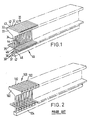
- Tag pin fastener assembly 20 includes a first tag pin assembly member 30 and a second tag pin assembly member 40.
- First assembly member 30 includes a plurality of tag pins 32 and second assembly member 40 includes a plurality of tag pins 42.
- tag pins 32 are alternatively arranged with respect to tag pins 42.
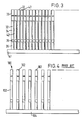
- First fastener assembly member 30 includes a plurality of tag pins 32 each of which include a plate-type head section 33 and a lateral rod or cross-bar 35 which are coupled together by a connecting string or filament 34.
- a connecting neck 36 extends from cross-bar 35 in a direction opposite to filament 34 such that tag pins 32 can be coupled through their respective connecting necks 36 to a connecting rod 37.
- Connecting rod 37 includes a bonding surface 38 as best depicted in Figs. 5 through 7. which is at the lower side of connecting neck 36 in the longitudinal direction. Bonding surface 38 is formed in such a way that it makes substantially a right angle with surface 39 of the lower end of connecting neck 36.
- Connecting neck 36 and connecting rod 37 are coupled at a connecting region 31 which is about half of the diameter of connecting neck 36.
- connecting neck 36 is formed partially on connecting rod 37 such that about half of connecting neck 36 indicated at 31, is formed on connecting rod 37 and the other half of connecting neck 36, indicated at 39, extends off of connecting rod 37 so as to substantially form a right angle with bonding surface 38.
- Outer surface 31a of connecting rod 37 at the side thereof which is opposite to bonding surface 38 protrudes out from the connecting region 31 of neck 36.
- Surface 31a can be made rectangular, circular, or the like.
- the thickness of the corresponding head sections 33, 43 and the diameter of the corresponding filaments 34, 44, cross bars 35, 45 and connection necks 36, 46 are between about 0.8 and 1.0 mm, and the distance between the fasteners on connecting rods 37 and 47 is between about 0.8 and 1.0 mm so that the fasteners of the two assemblies can be alternately inserted and positioned between corresponding fasteners on the other assembly.
- Such numerical examples are not necessarily required and the thicknesses, distances and diameters can be altered so long as the fasteners of one assembly member fit between and can be inserted between the fasteners of the other assembly member.
- Tag pins 32 are formed on connecting rod 37 such that there is a predetermined spacing between each of tag pins 32. Similarly, tag pins 42 are arranged on connecting rod 47 at substantially the same predetermined spacing. Accordingly, tag pins 32 will be alternately arranged with respect to tag pins 42 when they are brought together and their respective connecting rods 37 and 47 coupled together.
- Prior art tag pin assemblies are depicted in Figs. 2 and 4.
- Prior art tag pin assembly 100 includes a plurality of tag pins 102 which are integrally molded on a connecting rod 104. Due to mold limitations as described in detail above, spacing between adjacent tag pins 102 is limited by the thickness of the mold walls in the mold. Comparing Fig. 2 to Fig. 1 and Fig. 4 to Fig. 3, it is seen that the present invention permits a much more closely spaced tag pin assembly than was heretofore available in prior art constructions. Accordingly, the present invention obtains each of the objects and advantages detailed above.
- first and second tag pin assembly members are formed in a mold.
- the first and second tag pin assemblies each include a plurality of tap pins coupled to a separate connecting rod in predetermined spacing.
- Fasteners 32 of first fastener assembly member 30 are alternately inserted between fasteners 42 of second fastener assembly 40 such that they lie in a straight line.
- Corresponding head sections 33 and 43 and corresponding cross bars 35 and 45 of each fasteners lie in the same plane and connecting filaments 34 and 44 are positioned on the same vertical plane in the longitudinal direction.
- Fastener assembly members 30 and 40 are then coupled such as by bonding at the bonding surfaces 38 and 48 of the respective connecting rods 37 and 47. When the bonding surfaces 38 and 48 are bonded together, the lower end surfaces 39 and 49 of connectiong necks 36 and 46, respectively, of fasteners 30 and 40 are positioned over the upper surfaces of the other connecting rod of the other fastener assembly.
- Bonding of the bonding surfaces of connecting rods 37 and 47 can be achieved by a plurality of methods such as by a high frequency bonding method, and ultrasonic bonding method, by use of bonding adhesives or by bonding by melt fusion or heat. It is noted that the first and second assembly members can be bonded together before filaments 34 and 44 are stretched, however, the assembly members may also be coupled after stretching of the respective filaments has been carried out.
- the thickness of the head section and the diameter of the filament and cross bar of each fastener are reduced somewhat while the distance between the fasteners is made narrower to between about 0.2 to 0.4 mm.
- a unit length of the asseembly contains twice as many fasteners as in a conventional assembly. Accordingly, the package size can be reduced in half, thereby making it possible to load a fastener assembly with 100 tag pins into a tag pin attaching gun which in the prior art generally contained about 50 tag pins. Accordingly, the time for reloading the tag attaching gun can be substantially reduced.
- the present invention when the present invention is utilized, weakening of the die wall and damage to the die can be prevented which occurred when it was attempted to reduce the thickness of the head and the diameter of the filament and cross bar of the fastener in a single mold as in the prior art.
- the distance between the fasteners can be equal to or even wider than the conventional spacing and, consequently, the mold for making the fastener assemblies can have a longer useful life.
- Figs. 8 and 9 depict a second embodiment of the present invention wherein connecting rod 57 includes a groove 62 and connecting rod 67 includes a corresponding tongue 72 adapted to fit into groove 62.
- tongue 72 will lie in grooves 62 to provide a better and tighter bonding.
- the tongue and groove arrangement can be such that a snap-fit occurs whereby the two members would be held together by a friction-snap fit.
- groove 62 and tongue 72 can be formed along the entire lengths of connecting rods 57 and 67, respectively.
- a plurality of openings or holes 62 may be provided along connecting rod 57 with corresponding projections on connecting rod 67 such that the projections fit or snap-fit into the corresponding openings in connecting rod 57.
- the tongue and groove can be formed in any shape so long as the tongue and groove can be engaged, depending only on the characteristics of the bonding machine and the machine for making the molds. ,
- head section 33 was made to be 0.9 mm with a diameter of the filament 34, cross-bar 35 aod connecting neck 36 made to be 0.9 mm with a distance between fasteners made to be about 1.0 mm.
- Fastener assembly 30 was formed to contain 50 fasteners.
- Connecting rod 37 was formed such that bonding surface 38 was formed under neck 36 at the center line thereof with the connecting rod being coupled to the connecting neck 36 through connecting section 31.
- Fastener assembly 40 was formed in the same manner as fastener assembly 30.
- Fastener assemblies 30 and 40 were positioned such that the corresponding bonding surfaces 38 and 48 of corresponding connecting rods 37 and 47 faced each other. Then, fasteners 42 of section member 40 were allowed to be alternately inserted between fasteners 32 of first member 30. Bonding surfaces 38 and 48 of corresponding connecting rods 37 and 47 were bonded by a high frequency heating method while the bottom surfaces of the connecting rods 37 and 47 were positioned on the same plane. In this way, a fastener assembly containing 100 individual tag pins was obtained.
- the fastener assemblies which are to be mutually combined are put together such that each of the fasteners in one assembly are alternately inserted between the fasteners of the other assembly.
- the connecting rods are then coupled together. Therefore, the thickness of a fastener.and a fastener assembly has to be at most equal to or slightly smaller than the distance between two adjacent fasteners. For example, when the thickness of a fastener is between 0.8 mm and 0.9 mm, the distance between the adjacent fasteners should be between 0.9 mm and 1 mm.
- the connecting rods of the assemblies to be bonded are formed only atone side ofthe lower section at the center where coupling to the connection necks is made such that the bonding surface is below the neck. Consequently, when the two assemblies are coupled together, the bonding surface formed on the connecting rod of each assembly is bonded to the corresponding bonding surface of the other assembly. In this fashion, the fasteners of each assembly are inserted between the fasteners of the adjacent assembly and are kept in a straight line.
Landscapes
- Engineering & Computer Science (AREA)
- Mechanical Engineering (AREA)
- Physics & Mathematics (AREA)
- General Physics & Mathematics (AREA)
- Theoretical Computer Science (AREA)
- Labeling Devices (AREA)
- Slide Fasteners, Snap Fasteners, And Hook Fasteners (AREA)
Claims (16)
Applications Claiming Priority (2)
| Application Number | Priority Date | Filing Date | Title |
|---|---|---|---|
| KR1019840000259A KR850001851B1 (ko) | 1984-01-21 | 1984-01-21 | 파스너 조립체 및 그 제조방법 |
| KR25984 | 1984-01-21 |
Publications (3)
| Publication Number | Publication Date |
|---|---|
| EP0154390A2 EP0154390A2 (fr) | 1985-09-11 |
| EP0154390A3 EP0154390A3 (en) | 1986-07-30 |
| EP0154390B1 true EP0154390B1 (fr) | 1990-01-03 |
Family
ID=19232652
Family Applications (1)
| Application Number | Title | Priority Date | Filing Date |
|---|---|---|---|
| EP85300317A Expired - Lifetime EP0154390B1 (fr) | 1984-01-21 | 1985-01-17 | Assemblages d'épingles pour étiquettes et son procédé de fabrication |
Country Status (6)
| Country | Link |
|---|---|
| US (1) | US4586609A (fr) |
| EP (1) | EP0154390B1 (fr) |
| JP (1) | JPS60228230A (fr) |
| KR (1) | KR850001851B1 (fr) |
| CA (1) | CA1248330A (fr) |
| DE (1) | DE3575216D1 (fr) |
Families Citing this family (19)
| Publication number | Priority date | Publication date | Assignee | Title |
|---|---|---|---|---|
| US5987719A (en) * | 1993-06-28 | 1999-11-23 | Avery Dennison Corporation | Tamper resistant plastic fastener |
| AU716385B2 (en) * | 1996-10-22 | 2000-02-24 | Thomas & Betts International, Inc. | Cable tie bandoliers for use with automatic tools |
| US5967316A (en) * | 1997-10-22 | 1999-10-19 | Thomas & Betts International, Inc. | Cable tie bandoliers for use with automatic tools |
| US6418597B1 (en) | 1998-07-15 | 2002-07-16 | Avery Dennison Corporation | Plastic fastener, fastener clip, fastener dispensing tool and method of fastening objects |
| US6129206A (en) * | 1998-07-15 | 2000-10-10 | Avery Dennison Corporation | Fastener clip |
| US6173836B1 (en) | 1998-07-15 | 2001-01-16 | Avery Dennison Corporation | Fastener clip |
| US6267285B1 (en) | 1998-07-15 | 2001-07-31 | Avery Dennison Corporation | Plastic fastener, fastener clip, fastener dispensing tool and method of fastening objects |
| US6308386B1 (en) * | 1998-07-15 | 2001-10-30 | Avery Dennison Corporation | Fastener clip and method of making the same |
| US6837413B1 (en) | 1999-03-02 | 2005-01-04 | Avery Dennison Corporation | Plastic fastener, fastener clip, fastener dispensing tool and method of fastening objects |
| WO2000051792A2 (fr) * | 1999-03-02 | 2000-09-08 | Avery Dennison Corporation | Agrafe en matiere plastique, pince d'agrafage, outil distributeur d'agrafes et procede d'agrafage d'objets |
| USD464563S1 (en) | 2001-01-23 | 2002-10-22 | Avery Dennison Corporation | Clip of plastic fasteners |
| USD463733S1 (en) | 2001-01-24 | 2002-10-01 | Avery Dennison Corporation | Clip of plastic fasteners |
| USD463259S1 (en) | 2001-01-24 | 2002-09-24 | Avery Dennison Corporation | Plastic fastener |
| US7356884B2 (en) * | 2003-12-18 | 2008-04-15 | 3M Innovative Properties Company | Fastener for a display page |
| US7207095B2 (en) * | 2004-06-01 | 2007-04-24 | National Nail Corporation | Process for forming elongated flexible strip of nailing caps |
| US20080235918A1 (en) * | 2007-04-02 | 2008-10-02 | Laura Mooney | Fastener |
| USD580259S1 (en) * | 2007-04-02 | 2008-11-11 | Blumenthal Lansing Co. | Fastener |
| USD742730S1 (en) | 2014-07-21 | 2015-11-10 | National Nail Corp. | Set of fastener caps |
| US11542709B2 (en) * | 2020-01-06 | 2023-01-03 | Jd Russell Company | Protective cap for reinforcement bars |
Family Cites Families (3)
| Publication number | Priority date | Publication date | Assignee | Title |
|---|---|---|---|---|
| BE792298A (fr) * | 1972-05-25 | 1973-03-30 | Dennison Mfg Co | Perfectionnements aux attaches pour la reunion de deux objets ensemble |
| US4347932A (en) * | 1977-10-27 | 1982-09-07 | Clements Industries, Inc. | Tag pin |
| US4392906A (en) * | 1981-09-09 | 1983-07-12 | Toska Co., Ltd. | Method of and apparatus for manufacturing fastener assemblies |
-
1984
- 1984-01-21 KR KR1019840000259A patent/KR850001851B1/ko not_active Expired
-
1985
- 1985-01-10 CA CA000471860A patent/CA1248330A/fr not_active Expired
- 1985-01-17 DE DE8585300317T patent/DE3575216D1/de not_active Expired - Fee Related
- 1985-01-17 EP EP85300317A patent/EP0154390B1/fr not_active Expired - Lifetime
- 1985-01-18 US US06/692,734 patent/US4586609A/en not_active Expired - Fee Related
- 1985-01-21 JP JP60007616A patent/JPS60228230A/ja active Pending
Also Published As
| Publication number | Publication date |
|---|---|
| CA1248330A (fr) | 1989-01-10 |
| KR850001851B1 (ko) | 1985-12-28 |
| KR850005323A (ko) | 1985-08-24 |
| DE3575216D1 (de) | 1990-02-08 |
| EP0154390A2 (fr) | 1985-09-11 |
| JPS60228230A (ja) | 1985-11-13 |
| EP0154390A3 (en) | 1986-07-30 |
| US4586609A (en) | 1986-05-06 |
Similar Documents
| Publication | Publication Date | Title |
|---|---|---|
| EP0154390B1 (fr) | Assemblages d'épingles pour étiquettes et son procédé de fabrication | |
| US6293399B1 (en) | Fastener clip | |
| JPH0121963B2 (fr) | ||
| US6003209A (en) | Filamentary fastener and method of making same using insert molding | |
| CA1238881A (fr) | Groupement de fixations | |
| US20030011097A1 (en) | Continuously connected fastener stock and method of manufacturing the same | |
| KR940703627A (ko) | 치솔대에 치솔모를 고정하는 개선 방법(improved method of fas-tening bristle tufts to bristle carrier) | |
| JPH05295642A (ja) | 長尺ボールチェーンと継ぎ具 | |
| US4201814A (en) | Mesh structures | |
| US6308386B1 (en) | Fastener clip and method of making the same | |
| CA2337769C (fr) | Bride de fixation | |
| US6427895B1 (en) | Needle useful in the dispensing of plastic fasteners and method of manufacturing said needle | |
| US6318553B1 (en) | Plastic fastener and needle well-suited for use in the dispensing thereof | |
| WO1995009937A1 (fr) | Fabrication d'aiguilles s'utilisant dans la distribution d'elements de fixation en plastique | |
| CA2241084C (fr) | Serre-cables en bande a utiliser avec des outils automatiques | |
| JPH01238805A (ja) | 面フアスナー部材の製造方法 | |
| US20040031838A1 (en) | Plastic fasteners, needles for dispensing and method of manufacture | |
| JPS6189831A (ja) | フアスナー装置、およびその製造に用いられるモールド | |
| US5158729A (en) | Process for producing a tube sheet | |
| IT9083474A1 (it) | Elemento di rinforzo tubolare e procedimento per realizzarlo | |
| EP1311434B1 (fr) | Agents de fixation plastiques et aiguilles d'application | |
| EP0192916B1 (fr) | Bobine pour fils | |
| US6877907B2 (en) | Arrangement of several ferrules for optical waveguides and process of manufacturing a belt of plastic ferrules | |
| KR900004482B1 (ko) | 파스너 조립체용 부재 및 그 부재를 이용한 파스너 조립체의 제조방법 | |
| JPH0532239A (ja) | 係止片群担持連続体 |
Legal Events
| Date | Code | Title | Description |
|---|---|---|---|
| PUAI | Public reference made under article 153(3) epc to a published international application that has entered the european phase |
Free format text: ORIGINAL CODE: 0009012 |
|
| AK | Designated contracting states |
Designated state(s): BE DE FR GB IT NL |
|
| PUAL | Search report despatched |
Free format text: ORIGINAL CODE: 0009013 |
|
| AK | Designated contracting states |
Kind code of ref document: A3 Designated state(s): BE DE FR GB IT NL |
|
| 17P | Request for examination filed |
Effective date: 19861006 |
|
| 17Q | First examination report despatched |
Effective date: 19881111 |
|
| GRAA | (expected) grant |
Free format text: ORIGINAL CODE: 0009210 |
|
| AK | Designated contracting states |
Kind code of ref document: B1 Designated state(s): BE DE FR GB IT NL |
|
| PG25 | Lapsed in a contracting state [announced via postgrant information from national office to epo] |
Ref country code: NL Effective date: 19900103 Ref country code: IT Free format text: LAPSE BECAUSE OF FAILURE TO SUBMIT A TRANSLATION OF THE DESCRIPTION OR TO PAY THE FEE WITHIN THE PRESCRIBED TIME-LIMIT;WARNING: LAPSES OF ITALIAN PATENTS WITH EFFECTIVE DATE BEFORE 2007 MAY HAVE OCCURRED AT ANY TIME BEFORE 2007. THE CORRECT EFFECTIVE DATE MAY BE DIFFERENT FROM THE ONE RECORDED. Effective date: 19900103 Ref country code: FR Free format text: THE PATENT HAS BEEN ANNULLED BY A DECISION OF A NATIONAL AUTHORITY Effective date: 19900103 Ref country code: BE Effective date: 19900103 |
|
| REF | Corresponds to: |
Ref document number: 3575216 Country of ref document: DE Date of ref document: 19900208 |
|
| PG25 | Lapsed in a contracting state [announced via postgrant information from national office to epo] |
Ref country code: GB Effective date: 19900303 |
|
| EN | Fr: translation not filed | ||
| NLV1 | Nl: lapsed or annulled due to failure to fulfill the requirements of art. 29p and 29m of the patents act | ||
| PG25 | Lapsed in a contracting state [announced via postgrant information from national office to epo] |
Ref country code: DE Effective date: 19901002 |
|
| PLBE | No opposition filed within time limit |
Free format text: ORIGINAL CODE: 0009261 |
|
| STAA | Information on the status of an ep patent application or granted ep patent |
Free format text: STATUS: NO OPPOSITION FILED WITHIN TIME LIMIT |
|
| GBPC | Gb: european patent ceased through non-payment of renewal fee | ||
| 26N | No opposition filed |