EP0154461A2 - Gerät zur Umwälzung von Raumluft - Google Patents
Gerät zur Umwälzung von Raumluft Download PDFInfo
- Publication number
- EP0154461A2 EP0154461A2 EP85301194A EP85301194A EP0154461A2 EP 0154461 A2 EP0154461 A2 EP 0154461A2 EP 85301194 A EP85301194 A EP 85301194A EP 85301194 A EP85301194 A EP 85301194A EP 0154461 A2 EP0154461 A2 EP 0154461A2
- Authority
- EP
- European Patent Office
- Prior art keywords
- air
- room
- room air
- case
- temperature
- Prior art date
- Legal status (The legal status is an assumption and is not a legal conclusion. Google has not performed a legal analysis and makes no representation as to the accuracy of the status listed.)
- Withdrawn
Links
Images





Classifications
-
- F—MECHANICAL ENGINEERING; LIGHTING; HEATING; WEAPONS; BLASTING
- F24—HEATING; RANGES; VENTILATING
- F24F—AIR-CONDITIONING; AIR-HUMIDIFICATION; VENTILATION; USE OF AIR CURRENTS FOR SCREENING
- F24F11/00—Control or safety arrangements
- F24F11/0001—Control or safety arrangements for ventilation
-
- F—MECHANICAL ENGINEERING; LIGHTING; HEATING; WEAPONS; BLASTING
- F24—HEATING; RANGES; VENTILATING
- F24F—AIR-CONDITIONING; AIR-HUMIDIFICATION; VENTILATION; USE OF AIR CURRENTS FOR SCREENING
- F24F7/00—Ventilation
- F24F7/04—Ventilation with ducting systems, e.g. by double walls; with natural circulation
- F24F7/06—Ventilation with ducting systems, e.g. by double walls; with natural circulation with forced air circulation, e.g. by fan positioning of a ventilator in or against a conduit
- F24F7/065—Ventilation with ducting systems, e.g. by double walls; with natural circulation with forced air circulation, e.g. by fan positioning of a ventilator in or against a conduit fan combined with single duct; mounting arrangements of a fan in a duct
Definitions
- This invention relates to a package air conditioner which is generally used as an air conditioner for homes and every kind of offices, and it relates to a room air circulating apparatus for compulsorily circulating room air to be a temperature control medium in a room when it is used jointly with a stove provided fuels such as petroleum and gas.
- a package air conditioner though computerized control such as a use of IC contributes greatly to improving the quality, whether a hanging type or floor type, is employed by a single circulate route form in which room air is inhaled from particular level and either heated or cooled through a heat exchange, the heated or cooled air thereafter is exhaled into a room from a particular level which does not obstruct saio air to be inhaleo.
- most apparatuses are provided with a thermistor sensor being equipped with an inhale gate for controlling room temperature.
- above-mentioned package air conditioner being widely used at present causes great variation of temperature in different parts of a room if it is solely employed for heating or cooling, although there is slight variance due to a setting type of an apparatus and a direction of heated or cooled air to be exhaled.
- temperature between the upper and lower level of a room is tens to 20 degrees Celsius in winter and 5 to 10 degrees even in summer due to a draft effect causing warm air to mass near a ceiling level and cool air to stagnate around floor, and room air stays because of obstacles such as desks, charis, and counters. These conditions are unfavorable for health as well as unpleasant.
- temperature to be determined is set higher or lower than necessary for providing pleasant temperature in a dwelling zone, which generates a great loss of energy leading to a rise in running cost.
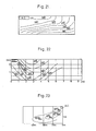
- Fig. 18 of a temperature distribution diagram the temperature at the upper level in a room reaches 30°C or higher, while that of the floor level is apploximately 20 0 C, presenting the large temperature variation.
- the above-mentioned state results from that heated air ascends while cool air descends, wherein air constantly circulates at the higher level than the middle in the room and cool air in the lower level stagnates without flowing.
- various obstacles in the room typically such as desks and chairs cause the above tendency to grow further in a real case.
- Fig. 19 of a temperature distribution diagram blast air blown to the floor results in less variation of temperature between the upper and the lower levels than said case(l) due to less air stagnation to rise temperature of the lower level.
- Fig. 20 of a temperature distribution diagram at the level 1m from the floor a high temperature zone is partially produced at the center of the room, which moreover is the level of a head when a man sits on a chair. Therefore, blast air at high temperature directly blown gives an unpleasant feeling or blows off papers on a desk as well as produces unfavorable condition for health.
- Fig. 21 of a temprtature distribution diagram such large temperature variation as apploximately 20°C between the upper and the lower levels in the room, more particularly the temperature variation is larger than said 1(1) due to hot air zone at ceiling and cold air zone on floor.
- Fig. 22 of a temperature distribution diagram an air current of 0.5m/sec or haster which gives an unpleasant feeling is generated at the central part of a dwelling zone, about 1.5m high from the floor.
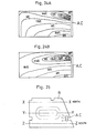
- Fig. 25 of a plane figure of an object room(R) and a cooling apparatus (A.C.) of a hanging type to be set so that air is exhaled horizontally the distribution of room temperature is measured at each cross sections of X-X, Y-Y, and Z-Z with distribution deagrams shown by Fig. 26 A,B, and C.
- both gates of inhaling room air and exhaling blast air being located near the ceiling permit high temperarure air at the upper level to be cooled by heat exchange, which results in a dreft effect due to which exhaled cool air descends naturally. Therefore, the temperature variation in the room is as ideal as apploximately 1°C at any part.
- the downward direction for exhaling air is desirable to promote a cooling effect in a dwelling zone where blast air (cool air) directly hits. Therefore, the temperature variation and a cooling effect in a dwelling zone contraoict each other.
- the invention is intended to provide a room air circulating apparatus which can realize pleasand and healthy heating and cooling by means of uniformalized and suitable room temperature even when it is employed jointly with various types of stove as well as with said package air conditioner.
- a room air circulating apparatus to be developed in order to attain the object mentioned above is so constructed as to inhale room air and exhale said inhaled air into a room, and the room air circulating apparatus comprising a hollow case in a box shape provided with an inhale gate for room air at least at a lower end of either an upper end or a lower end of the hollow case, a spout gate provided at an upper part of said hollow case in a box shape for exhaling inhaled air to a room, and a fan built in said hollow case in a box shape for inhaling and exhaling air.
- a room air circulating apparatus which is characterized in the manner mentioned above provides hereinafter operations.
- angles of exhaling cool or hot air from the package air conditioner and of exhaling room air from the circulating apparatus are set slightly upward from a horizontal plane, so that mixed air is situated at the level higher than a dwelling zone, resulting in flowing at high velocity. Hot air, being involved, generates lenient return air to be inhaled into this circualting apparatus.
- the circulating apparatus In spring and autumn without any necessity of heating or cooling, the circulating apparatus, if used solely, can provide pleasant coolness in accordance with the relations between circulated air and effective temperature.
- Another object of this invention is to make a whole apparatus thin ana small.
- a further object of this invention is to provide suitably humidifying effect at the time of heating for more pleasant air conditioning.
- Still a further object of this invention is so constructed to be fixed and used by minimizing both the occupancy within effective space and the injure of the fine appearance of a room.
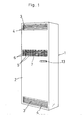
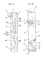
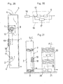
- (1) is a hollow case in a box shape apploximately 1,900 (mm) in whole height, about 6UU (mm) in width, and about 250 (mm) in depth so constructed as to stand by itself on the floor.
- suction gates (3), (3') are formed which may inhale room air both at the upper and the lower parts near ceiling ano floor respectivley in a room along a horizontal or nearly a horizontal plane.
- Rotary oamperers (4),(4') are provided with said suciton gates (3), (3') at both levels respectively which are so constructed as to open or close alternatively by means of opening and closing of the rotary dampers (4), (4').
- a fan (8) for inhaling and exhaling to be built in the case(l) comprises two multiblede fans(8A),(8B)laid at the upper and the lower ends of the case(l) respectively.
- An inhale flue(9) is so formed at the rear of the inside of the case (1) as to connect said two suction gates (3), (3') at both ends and inhale gates (8a), (8b) at the center of the rotation of said two multiblade fans (8A), (8B).
- Exhale gates(10A),(10B) are so formed as to connect spout gates (8a'), (8b') of said two multiblade fans (8A),(8B) and said spout gate(7) alternately by means of a diaphragm(11).
- Electric motors (12A), (12B) for driving said two multiblade fans (8A),(8B) are so connected with a controller as to stop operation automatically and reversibly when the temperature of room air to be inhaled from said gate (3)or (3') reaches the determined value. Since the electric motors are constructed in a very generally matter to omit the description thereof. (13) illustrates an operation switch.
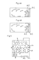
- a general embodiment of a room air circualting apparatus (shown.as S.C. in Figures) being constructed in the manner mentioned above is employed stanaing by itself either at the side or the rear of a floor type package air conditioner (shown as A.C. in Figures) according to Figs. 4A, B in either case of heating or cooling.
- both in heating ano cooling cases by means of setting the angle at which warm or cool air is exhaled from the pa;ckage air conditioner (A.C.), the mixed air to be generated by mixture of the warm or cool air exhaled from the package air conditioner (A.C.) and the air blown from the room air ciacualting apparatus can be laegely circualted in a room, actualizing heating or coling with little temperature variation.
- a further embodiment will be hereinafter described by means of the sole employment of the circualting apparatus in spring and autumn when there is no need of heating and cooling, generating proper amount of a current around a human body so as to give a pleasant feeling suitably.
- FIG. 27 illustrating a modified embodiment by means of two fans, in the above-mentioned embodiment, it may be so constructed that the room air may be inhaled from the suction gate(3') at the lower end and exhaled into a room from the spout- gate(7) by omitting the suction gate(3) at the upper end.
- This embodiment is particualrly aimed at a high-ceiled room, where hot air stagnating further higher level than the dwelling zone does not influence a cooling effect very much so that air is left without being circulated.
- the second embodiment to be hereinafter described structually differentiates from the first embodiment in respcts to be described hereinafter, but it is almost identical in its function.
- the explanation of the identical parts of the two embodiemnts are omitted by that - the identical symbols being used.
- the second embodiment differentiates from the first embodiment in that a single fan(8) for inhaling and exhaling is equipped inside the case(l) at the immediate rear of the spout gate (7) and that s humidifying device(16) which is surrounded by an endless belt made of the material with such properties as waterproof and permeability with unrestrictedly driving rotation through a motor(24) and a transmission belt(25) at the position between a water tank(14) as which the abse of said case(l) is so constructed and an inahle fluei9) of the air from said suction gate(3') at the lower end.
- a single fan(8) for inhaling and exhaling is equipped inside the case(l) at the immediate rear of the spout gate (7) and that s humidifying device(16) which is surrounded by an endless belt made of the material with such properties as waterproof and permeability with unrestrictedly driving rotation through a motor(24) and a transmission belt(25) at the position between a water tank(14
- the second embodiment is employed through almost the same circualtion illustrated by solid and chain lines at the time of heating and cooling as the operation of the first embodiment.
- the room air inhaled from said gate(3') is humidified by absorbing moisture kept at the endless belt(15) then additionally the humidified air being exhaled into a room and diffused by the circulation of the mixed air presents such advantages as to maintain the humidity of the room appropriately and produce a heating effect more consciously.
- Figs. 29 and 30 illustrating the third embodiment presenting the almost same construction as the second embodiment, comprises a sensor(17) for detecting the temperature of the room air to be inahled from said sauction gate (3) and a controller(19) for automatically controlling the revolving speed of a single fan(8) and the electric motor(12) corresponding to the temperature detected by the sensor(17) so taht the temperature of the room air can be maintained in the determined range to be set by a device(18) for determining temperature.
- a controller(19) for automatically controlling the revolving speed of a single fan(8) and the electric motor(12) corresponding to the temperature detected by the sensor(17) so taht the temperature of the room air can be maintained in the determined range to be set by a device(18) for determining temperature.
- a controller(19) for automatically controlling the revolving speed of a single fan(8) and the electric motor(12) corresponding to the temperature detected by the sensor(17) so taht the temperature of the
- the floor type of package air conditioner (A.C.) to be employed jointly comprises mechanism of both a fan motor (20) and a compressor(21) to be electrically connected with said controller(19) of the apparatus (S.C.) so taht this apparatus (S.C.) and the package air conditioner are controlled synchronously, as a result of which the room temperature can be uniformalized more effectively.
- (26) of Fig. 31 shows a device for opening and closing electromagnetically.
- said hollow case in a box shape is so constructed as to be fixed outside of-a wall(21) of a building outdoors therein pipes(3A),(3A'), and(7A) are laid continuously in the wall(21) and permitting said suction gates(3), (3')of both ends and said spout gate(7) to be open in a room in above-mentioned condition.
- pipes(3A),(3A'), and(7A) are laid continuously in the wall(21) and permitting said suction gates(3), (3')of both ends and said spout gate(7) to be open in a room in above-mentioned condition.
- the embooiment of a single fan(8) is shown, two fans can be employed.
- the fourth embodiment presents practical effects by offsetting such disadvantages as deteriorating the space utilization rate or injuring the fine appearance of the room by means of the case(l) to be employed outdoors.
- a gate(23) for inhaling outside air provided with a damper(22) for opening and closing can be formed near the position of the inahle gate(8a) of the fan(8) on the rear wall of the case(l) as shown in Fig. 33.
- ventilation is executed at the same time which permits the apparatus to be effectively employed for the exclusive use of ventialtion in spring and autimn.
- the case (1) can be so constructed sa to be built in though no drawing is shown thereof.
- the case(1) can be so constructed as to stand by itself at a veranda or on the ground.
- Fig. 5 in a room of plane shape about 10.5m ⁇ 10.5m ⁇ 2.9m in length x width x height respectively (floor area 110.25mA, capacity 319.7m') where office deska(d), counters (c), cabinets(k), a set of a table and chairs for rrecréation(s), and chairs(ch) are arranged as illustrated, room temperatures at the points of A to G inclucive are measured in a condition of actual business performances.
- digital temperature recorder Model 3874 manufactured by Yokogawa Electric Works, Ltd.
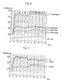
- Figs. 7 to 13 inclusive show the room temperature variation at the measured points A to G
- Fig. 6 shows the temperature variation of outside air, the suction gate and the spout gate of the air conditioner (A.C.) and the apparatus (S.C.) respectively, resulting hereinafter;
- the temperature at the suction gate of the air conditioner drops about 10°C, and slight increase as a whole after fluctuation is shown at the spout gate.
- the temperature at the high and middle part of the points A to 0 inclusive reduces about 2°C to 4°C while the temperature at the low part increases 3°C to 9°C.
- the temperature variation at the middle part is modest and about 4°C increase is shown at the low part.
- the remarkable decrease and increase of temperature are shown at the top part and the bottom part respectively at the points A, C,C,D,which are farther from the air conditioner.
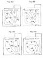
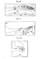
- Figs. 16A and 17A illustrating the currents at 1.5m and 2.5m higher than the floor level respectively when the air conditioner is solely used, while referring to Figs. 16B and 17B illustrating the current respectively of the above-emntioned heights when the apparatus is jointly employed, which results in hereinafrer;
- the velocity at the time of joint employment is twice as much as the case of sole employment, resulting in the circulation of the air in large quantity.
- the current at the left of the position of the air conditioner largely moves counterclockwise, while at the right the air exhaled to the ceiling circualted with large velocity, which permits cool air in'large quantity at the lower level to be inhaled into the suction gate at the lower end of the apparatus.
Landscapes
- Engineering & Computer Science (AREA)
- Chemical & Material Sciences (AREA)
- Combustion & Propulsion (AREA)
- Mechanical Engineering (AREA)
- General Engineering & Computer Science (AREA)
- Air Conditioning Control Device (AREA)
- Ventilation (AREA)
Applications Claiming Priority (6)
| Application Number | Priority Date | Filing Date | Title |
|---|---|---|---|
| JP2523684 | 1984-02-25 | ||
| JP25236/84 | 1984-02-25 | ||
| JP158088/84 | 1984-07-27 | ||
| JP59158088A JPS60178234A (ja) | 1984-07-27 | 1984-07-27 | 送風式冷暖房機 |
| JP13026684U JPS6146327U (ja) | 1984-08-28 | 1984-08-28 | 空調用補助送風装置 |
| JP130266/84U | 1984-08-28 |
Publications (2)
| Publication Number | Publication Date |
|---|---|
| EP0154461A2 true EP0154461A2 (de) | 1985-09-11 |
| EP0154461A3 EP0154461A3 (de) | 1987-07-15 |
Family
ID=27284946
Family Applications (1)
| Application Number | Title | Priority Date | Filing Date |
|---|---|---|---|
| EP85301194A Withdrawn EP0154461A3 (de) | 1984-02-25 | 1985-02-22 | Gerät zur Umwälzung von Raumluft |
Country Status (1)
| Country | Link |
|---|---|
| EP (1) | EP0154461A3 (de) |
Cited By (7)
| Publication number | Priority date | Publication date | Assignee | Title |
|---|---|---|---|---|
| GB2335267A (en) * | 1998-03-10 | 1999-09-15 | Pdl Holdings Ltd | Air heaters |
| CN1061416C (zh) * | 1997-08-19 | 2001-01-31 | 吴凤清 | 自然风电风扇 |
| CN105240930A (zh) * | 2015-09-11 | 2016-01-13 | 珠海格力电器股份有限公司 | 风量调节装置及方法和空调柜机 |
| CN105716150A (zh) * | 2016-03-29 | 2016-06-29 | 苏州泰隆制冷有限公司 | 一种多风区空调 |
| CN106151081A (zh) * | 2014-12-31 | 2016-11-23 | Lg电子株式会社 | 送风机及具有该送风机的空气调节器 |
| CN106382732A (zh) * | 2016-08-25 | 2017-02-08 | 珠海格力电器股份有限公司 | 空调器 |
| CN107642494A (zh) * | 2016-07-20 | 2018-01-30 | Lg电子株式会社 | 吹风机 |
Family Cites Families (4)
| Publication number | Priority date | Publication date | Assignee | Title |
|---|---|---|---|---|
| US2635524A (en) * | 1949-04-04 | 1953-04-21 | Ralph D Jenkins | Air circulating or ventilating unit |
| DE2157818B2 (de) * | 1971-11-22 | 1981-06-04 | LTG Luftechnische GmbH, 7000 Stuttgart | Anordnung zum Temperieren von Räumen |
| US4152973A (en) * | 1977-09-16 | 1979-05-08 | Peterson Fred M | Heat energy homogenizer |
| BE898034A (fr) * | 1983-10-19 | 1984-02-15 | Lagasse Philippe | Commande automatisee de regulation thermique appareil a circulation d'air. |
-
1985
- 1985-02-22 EP EP85301194A patent/EP0154461A3/de not_active Withdrawn
Cited By (9)
| Publication number | Priority date | Publication date | Assignee | Title |
|---|---|---|---|---|
| CN1061416C (zh) * | 1997-08-19 | 2001-01-31 | 吴凤清 | 自然风电风扇 |
| GB2335267A (en) * | 1998-03-10 | 1999-09-15 | Pdl Holdings Ltd | Air heaters |
| CN106151081A (zh) * | 2014-12-31 | 2016-11-23 | Lg电子株式会社 | 送风机及具有该送风机的空气调节器 |
| CN106151081B (zh) * | 2014-12-31 | 2019-02-22 | Lg电子株式会社 | 送风机及具有该送风机的空气调节器 |
| CN105240930A (zh) * | 2015-09-11 | 2016-01-13 | 珠海格力电器股份有限公司 | 风量调节装置及方法和空调柜机 |
| CN105240930B (zh) * | 2015-09-11 | 2017-12-19 | 珠海格力电器股份有限公司 | 风量调节装置的风量调节方法 |
| CN105716150A (zh) * | 2016-03-29 | 2016-06-29 | 苏州泰隆制冷有限公司 | 一种多风区空调 |
| CN107642494A (zh) * | 2016-07-20 | 2018-01-30 | Lg电子株式会社 | 吹风机 |
| CN106382732A (zh) * | 2016-08-25 | 2017-02-08 | 珠海格力电器股份有限公司 | 空调器 |
Also Published As
| Publication number | Publication date |
|---|---|
| EP0154461A3 (de) | 1987-07-15 |
Similar Documents
| Publication | Publication Date | Title |
|---|---|---|
| US4738188A (en) | Room air circulating apparatus | |
| US3517601A (en) | Air intake,mixer and recirculator system | |
| JP2561749B2 (ja) | クリ−ンル−ムの空気循環方法 | |
| CN113932298B (zh) | 风机系统、空调器以及出风控制方法 | |
| EP0154461A2 (de) | Gerät zur Umwälzung von Raumluft | |
| CN216620037U (zh) | 风机系统以及空调器 | |
| JPH0233064Y2 (de) | ||
| JP7157366B1 (ja) | パーティション | |
| JPH0150817B2 (de) | ||
| JPH023092B2 (de) | ||
| JPS6225607Y2 (de) | ||
| JPS60142141A (ja) | 空気調和機 | |
| EP0150888A2 (de) | Computergesteuerte Klimaanlage | |
| JPH0779592B2 (ja) | 鶏 舎 | |
| JP2511985B2 (ja) | 空気調和機 | |
| CN219550681U (zh) | 一种空调器 | |
| US1948647A (en) | Air conditioning apparatus | |
| JPH04217733A (ja) | 空気調和機 | |
| JPH0233070Y2 (de) | ||
| JPH0233071Y2 (de) | ||
| JP3021044U (ja) | 高床型鶏舎 | |
| US2960022A (en) | Heat diffuser, humidifier, and draft eliminator | |
| RU93003236A (ru) | Конвективный ионизатор | |
| JPS6131828A (ja) | ヒ−トポンプ式空気調和機 | |
| US1433843A (en) | Heating and ventilating construction |
Legal Events
| Date | Code | Title | Description |
|---|---|---|---|
| PUAI | Public reference made under article 153(3) epc to a published international application that has entered the european phase |
Free format text: ORIGINAL CODE: 0009012 |
|
| AK | Designated contracting states |
Designated state(s): AT BE CH DE FR GB IT LI LU NL SE |
|
| PUAL | Search report despatched |
Free format text: ORIGINAL CODE: 0009013 |
|
| RHK1 | Main classification (correction) |
Ipc: F24F 7/06 |
|
| AK | Designated contracting states |
Kind code of ref document: A3 Designated state(s): AT BE CH DE FR GB IT LI LU NL SE |
|
| 17P | Request for examination filed |
Effective date: 19880115 |
|
| 17Q | First examination report despatched |
Effective date: 19890420 |
|
| STAA | Information on the status of an ep patent application or granted ep patent |
Free format text: STATUS: THE APPLICATION IS DEEMED TO BE WITHDRAWN |
|
| 18D | Application deemed to be withdrawn |
Effective date: 19890731 |
|
| RIN1 | Information on inventor provided before grant (corrected) |
Inventor name: NISHIDA, TAKASHI |