EP0154485B1 - Appareil d'enregistrement et/ou de reproduction de signaux vidéo possédant une fonction apte à mettre en oeuvre des enregistrements assemblés - Google Patents
Appareil d'enregistrement et/ou de reproduction de signaux vidéo possédant une fonction apte à mettre en oeuvre des enregistrements assemblés Download PDFInfo
- Publication number
- EP0154485B1 EP0154485B1 EP85301259A EP85301259A EP0154485B1 EP 0154485 B1 EP0154485 B1 EP 0154485B1 EP 85301259 A EP85301259 A EP 85301259A EP 85301259 A EP85301259 A EP 85301259A EP 0154485 B1 EP0154485 B1 EP 0154485B1
- Authority
- EP
- European Patent Office
- Prior art keywords
- recording
- signal
- tape
- control signal
- reproducing
- Prior art date
- Legal status (The legal status is an assumption and is not a legal conclusion. Google has not performed a legal analysis and makes no representation as to the accuracy of the status listed.)
- Expired - Lifetime
Links
Images



Classifications
-
- G—PHYSICS
- G11—INFORMATION STORAGE
- G11B—INFORMATION STORAGE BASED ON RELATIVE MOVEMENT BETWEEN RECORD CARRIER AND TRANSDUCER
- G11B15/00—Driving, starting or stopping record carriers of filamentary or web form; Driving both such record carriers and heads; Guiding such record carriers or containers therefor; Control thereof; Control of operating function
- G11B15/02—Control of operating function, e.g. switching from recording to reproducing
- G11B15/05—Control of operating function, e.g. switching from recording to reproducing by sensing features present on or derived from record carrier or container
- G11B15/087—Control of operating function, e.g. switching from recording to reproducing by sensing features present on or derived from record carrier or container by sensing recorded signals
-
- G—PHYSICS
- G11—INFORMATION STORAGE
- G11B—INFORMATION STORAGE BASED ON RELATIVE MOVEMENT BETWEEN RECORD CARRIER AND TRANSDUCER
- G11B15/00—Driving, starting or stopping record carriers of filamentary or web form; Driving both such record carriers and heads; Guiding such record carriers or containers therefor; Control thereof; Control of operating function
- G11B15/18—Driving; Starting; Stopping; Arrangements for control or regulation thereof
- G11B15/1808—Driving of both record carrier and head
- G11B15/1875—Driving of both record carrier and head adaptations for special effects or editing
-
- G—PHYSICS
- G11—INFORMATION STORAGE
- G11B—INFORMATION STORAGE BASED ON RELATIVE MOVEMENT BETWEEN RECORD CARRIER AND TRANSDUCER
- G11B27/00—Editing; Indexing; Addressing; Timing or synchronising; Monitoring; Measuring tape travel
- G11B27/02—Editing, e.g. varying the order of information signals recorded on, or reproduced from, record carriers
- G11B27/022—Electronic editing of analogue information signals, e.g. audio or video signals
- G11B27/024—Electronic editing of analogue information signals, e.g. audio or video signals on tapes
Definitions
- the present invention generally relates to video signal recording and/or reproducing apparatuses having a function of carrying out assembled recordings, and more particularly to a video signal recording and/or reproducing apparatus which carries out an assembled recording by once stopping the recording operation, moving a tape in a reverse direction over a predetermined distance and then resuming the tape travel in a forward direction so as to start a new recording in continuance with a previous recording.
- the video signal recording and/or reproducing apparatus according to the present invention is designed to minimize an overlap between the previous recording and the new recording.
- a video signal recording and/or reproducing apparatus and especially in a video signal recording and/or reproducing apparatus which records an image-picked up video signal from a television camera on a tape
- the apparatus is frequently operated in such a manner that the recording operation is temporarily stopped during the recording operation and the recording operation is resumed thereafter. It is common to operate the apparatus in this manner when using a portable television camera and recording the image-picked up video signal on the tape by a portable recording and/or reproducing apparatus.
- an unrecorded part may be formed on the tape between a previously recorded part and a newly recorded part, or an overlapping part may be formed on the tape when the recording is resumed from a part overlapping the previously recorded part.
- the tape In order to eliminate the unwanted deviation in the tape position introduced during the tape unloading and loading operations, the tape is maintained in the state loaded in the predetermined tape path during predetermined modes of the apparatus, that is, measures are taken to prevent the tape from being unloaded during the predetermined modes of the apparatus.
- measures are taken to maintain the tape in the loaded state
- the traveling tape does not stop immediately after an operation is carried out to temporarily stop the tape, due to inertia of a tape feeding system.
- the tape actually stops after traveling over a certain distance.
- it will take a certain time period for the tape traveling speed to reach a predetermined tape traveling speed.
- a supply reel is automatically rotated in a tape take-up direction so as to rewind a predetermined quantity of tape before stopping the tape.
- the tape traveling speed will reach the predetermined tape traveling speed while the tape travel is resumed and the tape travels over a distance approximately corresponding to the rewound quantity of tape, when the recording operation is resumed.
- the new recording can be carried out satisfactorily in continuance with the previously recorded part when the recording operation is resumed after the tape traveling speed has reached the predetermined tape traveling speed.
- the number of control pulses reproduced from the tape is counted in order to detect that the tape has traveled over the predetermined distance.
- the number of pulses generated from a frequency generator which is coupled to a capstan motor is counted to detect that the tape has traveled over the predetermined distance.
- the tape traveling speed is extremely low when the tape is being stopped and when the tape is being started to travel. For this reason, the reproduction of the control pulses, the generation of the pulses by the frequency generator, and the counting of the pulses cannot be performed accurately during these times. As a result, it is impossible to accurately detect whether the tape has travelled over the predetermined distance during these times. Accordingly, in order to prevent an unrecorded part from being formed between the end of the previously recorded part and the start of the newly recorded part, the conventional apparatus starts the new recording before the end of the previous recording is reached. In other words, when the tape is rewound over the predetermined distance and the tape travel is then resumed in the forward direction, the new recording is started from a position overlapping a part of the previous recording. For example, in the actual conventional apparatus, this overlap between the previous recording and the new recording on the tape exists over a distance corresponding to three to four the video signal frames.
- the pre-recorded signals of the previous recording are substantially erased by the new signals of the new recording, but an interference is introduced in the color signal.
- a reproduced picture having a satisfactory picture quality cannot be obtained from the overlap.
- the overlap is extremely small or does not exist.
- the overlap is made intentionally as described before so as to reduce the chances of an unrecorded part being formed between the previous recording and the new recording.
- DE-B-1762922 discloses an electronic editing apparatus for performing insert recording of a video signal.
- Previously recorded control pulses are reproduced to permit satisfactory insert recording. Thus, the previously recorded control pulses are not erased and no new control pulses are recorded.
- a video signal recording and/or reproducing apparatus which records a joint indication signal on a control track when the recording operation is once stopped, stops the tape after rewinding the tape over a predetermined distance, resumes the tape travel in a forward direction, and start a new recording when the joint indication signal is reproduced during an assembled recording.
- VTRs video tape recorders
- the mode of the apparatus is set to a recording mode from a time t1 and a recording pause switch 23 shown in Figure 2 is turned ON at a time t2 so as to once stop the recording.
- a joint indication signal is recorded on a control track of a tape during a minute time period between times t2 and t3.
- the mode of the apparatus is set to a reproducing mode and a capstan rotates in a reverse direction.
- the tape is taken up on a supply reel in the state where the tape is loaded in a predetermined tape path, and the tape travels in the reverse direction. While the tape is traveling in the reverse direction, the number of peak values of a frequency signal generated from a frequency generator which is provided on a reel or the capstan is counted. When the count reaches a predetermined value, the rotating reels are stopped. The tape stops traveling at a time t4.
- the recording pause switch 23 is turned OFF at a time t5 when an assembled recording is to be carried out so as to start a new recording in continuance with the previous recording described before.
- the apparatus assumes the reproducing mode from the time t5 and the capstan causes the tape to travel in a forward direction.
- the pre-recorded joint indication signal is detected after the tape traveling speed reaches a predetermined tape traveling speed. Due to the detection of the joint indication signal, the mode of the apparatus is switched to the recording mode at a time t7 and the new recording is started in continuance with the end of the previous recording.
- the apparatus of the present invention there is essentially no overlap between the previous recording and the new recording because the new recording is started upon reproduction of the pre-recorded joint indication signal which is recorded when the previous recording is once stopped.
- the conventional apparatus counts the reproduced control pulses or the output pulses of the frequency generator after the time t5, and the measurement of the tape traveling distance is inaccurate.
- the conventional apparatus is designed to start the new recording from a time t6 which is before the time t7. For this reason, an overlap of the previous and new recordings occurs between the times t6 and t7 according to the conventional apparatus.
- the apparatus according to the present invention is designed to start the new recording from the time t7, and thus, there is essentially no overlap between the previous and new recordings.
- a drum motor 12 rotates under control of a servo circuit 11 so as to rotate a rotary drum 13 having video heads 14a and 14b mounted at diametrical positions thereof.
- a capstan motor 15 also rotates under control of the servo circuit 11 so as to rotate a capstan 16.
- a magnetic tape 18 is driven in a state pinched between the capstan 16 and a pinch roller 17, and travels at a predetermined traveling speed.
- a video signal which is to be recorded is applied to an input terminal 19, and is supplied to a video signal processing circuit 21 wherein the video signal is subjected to a predetermined signal processing.
- the processed video signal from the video signal processing circuit 21 is supplied to the video heads 14a and 14b and is recorded on the traveling tape 18.
- the signal reproduced from the tape 18 by the video heads 14a and 14b is obtained through an output terminal 20.
- a drum pulse signal is obtained from a pickup head 22 which opposes a magnet mounted on a rotary shaft of the motor 12.
- the drum pulse signal is supplied to the servo circuit 11.
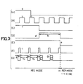
- a system controller 24 having a built-in microcomputer produces a pause signal a shown in FIG.3(A).
- This pause signal a is supplied to a D-type flip-flop 26 within a joint indication signal generating circuit 25.
- a drum pulse signal b shown in FIG.3(B) is applied to a clock terminal of the flip-flop 26 as a clock signal from the servo circuit 11.
- a signal c shown in FIG.3(C) which falls responsive to a first rise in the drum pulse signal b within the low-level period of the pause signal a , is obtained from the flip-flop 26.
- the output signal c of the flip-flop 26 is supplied to a monostable multivibrator 27.
- a signal d shown in FIG.3(D) which rises responsive to a fall in the signal c and then falls after a time T1 (for example, a time corresponding to two video signal frames) which is dependent on a time constant determined by the capacitance of a capacitor C1 and the resistance of a resistor R1 which are coupled to the monostable multivibrator 27.
- the output signal c of the flip-flop 26 and the output signal d of the monostable multivibrator 27 are supplied to a wired OR circuit comprising diodes D1 and D2.
- a signal e shown in FIG.3(E) is obtained from this wired OR circuit and is supplied to the system controller 24 as a recording interruption indication signal.
- a capacitor C2 and a resistor R2 are coupled to a monostable multivibrator 28.
- a connection point between the capacitor C2 and a resistor R3 is coupled to the output side of the monostable multivibrator 27 through a diode D5 and the resistor R2.
- a control signal f shown in FIG.3(F) is supplied to the monostable multivibrator 28 from the servo circuit 11. During the low-level period of the output signal d of the monostable multivibrator 27, the monostable multivibrator 28 is unaffected by the resistor R2.
- the monostable multivibrator 28 produces a signal g1 shown in FIG.3(G) which rises responsive to a fall in the signal f and then falls after a time T2 which is dependent on a time constant determined by the capacitance of the capacitor C2 and the resistance of the resistor R3.
- the diode D5 is turned ON and the resistor R2 is essentially coupled to the monostable multivibrator 28.
- the monostable multivibrator 28 produces in this case a signal g2 shown in FIG.3(G) which rises responsive to a fall in the signal f and then falls after a time T3 which is dependent on a time constant determined by the capacitance of the capacitor C2 and the resistance of the parallel-connected resistors R2 and R3, where the time T3 is smaller than the time T2.
- the duty factor of the signal g1 is equal to 75% and the duty factor of the signal g2 is equal to 25%.
- the timings with which the output signals g1 and g2 (hereinafter also generally referred to as a signal g ) of the monostable multivibrator 28 rise are determined by the timing with which the signal f falls, and the pulse interval with which the output signal g of the monostable multivibrator 28 rises is therefore constant.
- the timings with which the signals g1 and g2 fall are respectively dependent on the times T2 and T3 which are determined by different time constants.
- the period with which the signal g falls changes at a point where the signal g1 changes to the signal g2. This change in the period with which the signal g falls is used to detect a joint indication signal as will be described hereinafter.
- the output signal g of the monostable multivibrator 28 is amplified in a recording amplifier 29, and is supplied to a control head 30 through a resistor R4 and a capacitor C3. The signal g is thus recorded on a control track of the tape 18.
- the amplifier 29 receives a high-level signal from the system controller 24 during the recording mode, and is activated only during the recording mode.
- the signal e supplied to the system controller 24 falls at the time t3 and assumes a low level. Responsive to the fall in the signal e , the system controller 24 supplies a reverse rotation command signal to the servo circuit 11 so as to rotate the motor 15 in the reverse direction.
- the tape 18 travels in the reverse direction and is taken up on a supply reel (not shown) which rotates in the tape take-up direction. In other words, the tape 18 is rewound.
- the system controller 24 supplies a recording interrupt command signal to the video signal processing circuit 21 so as to put the video signal processing circuit 21 in a recording interrupt state.
- the signal applied to the amplifier 29 from the system controller 24 assumes a low level, and the amplifier 29 is deactivated. Hence, no control signal is recorded on the tape 18 as the tape 18 travels in the reverse direction.
- the system controller 24 supplies a stop signal to the servo circuit 11 and stops the motor 15 after counting a predetermined number of output signals of a frequency generator (not shown) which is provided on a reel or the capstan 16, or after a predetermined time determined by a built-in timer of the system controller 24 elapses.
- the tape 18 stops traveling in the reverse direction at the time t4.
- the distance over which the tape 18 travels in the reverse direction need not be strictly selected.
- the distance over which the tape 18 travels in the reverse direction simply needs to be sufficiently long so that when the tape travel in the forward direction is thereafter resumed, the tape traveling speed increases from zero to a predetermined tape traveling speed before the new recording (assembled recording) is started.
- the system controller 24 supplies a forward rotation command signal to the servo circuit 11.
- the motor 15 rotates in the forward direction and the tape 18 starts to travel in the forward direction.
- the signal applied to the amplifier 19 from the system controller 24 still assumes the low level, and the amplifier 19 remains in the deactivated state.
- the reproduced signal h is inverted and amplified in an inverting amplifier 31 and is supplied to a Schmitt trigger circuit 32 which produces a signal i shown in FIG.4(B).
- the signal i is supplied to a monostable multivibrator 34 within a joint indication signal detecting circuit 33.
- the monostable multivibrator 34 produces a signal j shown in FIG.4(C) which falls responsive to a fall in the signal i and then rises after a time T4 which is dependent on a time constant determined by the capacitance of a capacitor C4 and the resistance of a resistor R5 which are coupled to the monostable multivibrator 34.
- the time T4 is selected so that the duty factor of the signal j becomes equal to 50%.
- the signal j is differentiated in a differentiating circuit comprising a capacitor C5 and a resistor R6.
- a diode D3 obtains only the positive polarity differentiated pulses and applies these positive polarity differentiated pulses to one input terminal of an AND gate 35 as a signal k shown in FIG.4(D).
- the output signal i of the Schmitt trigger circuit 32 is applied to the other input terminal of the AND gate 35.
- the AND gate 35 performs a logical multiplication between the signals k and i , and produces a signal l shown in FIG.4(E).
- the signal k corresponds to the low-level part of the signal i when the reproduced signal h corresponds to the recorded signal g1 and the signal k corresponds to the high-level part of the signal i when the reproduced signal h corresponds to the recorded signal g2, and the signal l is produced from the AND gate 35 as the joint indication signal. Accordingly, the changing point where the signal g changes from the signal g1 to the signal g2 is detected.
- the output signal l of the AND gate 35 is passed through a diode D4 and is supplied to an integrating circuit comprising a capacitor C6 and a resistor R7.
- the integrating circuit produces a signal m shown in FIG.4(F) and supplies the signal m to a flip-flop 36.
- a drum pulse signal b shown in FIG.4(G) which is the same as the drum pulse signal b shown in FIG.3(B), is applied to a clock terminal of the flip-flop 36 as a clock signal from the servo circuit 11.
- the flip-flop 36 produces a signal n shown in FIG.4(H) which rises responsive to a first rise in the clock signal b during the high-level period of the signal m .
- the signal n is supplied to the system controller 24 as an assembled recording start command signal.
- the system controller 24 which receives the signal n , sets the servo circuit 11 and the video signal processing circuit 21 to the recording mode at the time t7. Hence, a new video signal which is to be recorded and is applied to the input terminal 19, is passed through the video signal processing circuit 21 and is recorded on the tape 18 by the video heads 14a and 14b.
- the assembled recording of the new video signal is started by detecting the pre-recorded joint indication signal which is recorded when the recording is interrupted. Hence, a relatively long overlap will not be formed between the previous recording and the new recording as in the case of the conventional apparatus. According to the apparatus of the present invention, even when an overlap does occur between the previous recording and the new recording, the length of the overlap on the tape 18 is short and corresponds to approximately one video signal frame at the maximum. Hence, the new recording can be made in satisfactory continuance with the previous recording. After the signal l is no longer detected, the signal m gradually assumes a low level and the level of the signal n also changes to a low level, but the system controller 24 maintains the recording mode.
- the timing with which the control signal rises is originally used to control the functions of the apparatus during the reproducing mode.
- the timing with which the control signal falls which timing is not essential to control the functions of the apparatus during the reproducing mode, is made different from the regular timing.
- the timing with which the control signal falls is made different from that of the regular control signal g1 and is made the same as that of the signal g1.
- the joint indication signal is detected by detecting the point when the timing with which the control signal falls changes. For this reason, it is unnecessary to record a special indication signal on the control track.
- the embodiment can be applied to a standard recording format in which no signal is recorded on the control track besides the control signal.
- the present invention is not limited to this embodiment, and an independent joint indication signal may be recorded on the control track besides the control signal.
Landscapes
- Engineering & Computer Science (AREA)
- Multimedia (AREA)
- Signal Processing (AREA)
- Management Or Editing Of Information On Record Carriers (AREA)
- Television Signal Processing For Recording (AREA)
- Indexing, Searching, Synchronizing, And The Amount Of Synchronization Travel Of Record Carriers (AREA)
Claims (5)
- Un appareil d'enregistrement et/ou de reproduction de signaux vidéo comprenant des moyens d'enregistrement (21, 13, 14a, 14b) incorporant un tambour rotatif (13) présentant des moyens à tête vidéo (14a, 14b) pour enregistrer un signal vidéo sur une bande (18) pendant un mode d'enregistrement et pour reproduire le signal vidéo à partir de la bande (18) pendant un mode de reproduction, des moyens d'entraînement de tambour rotatif (12) pour entraîner en rotation ledit tambour rotatif (13), des moyens d'entraînement de bande (24, 11, 15, 16) pour déplacer la bande (18) vers l'avant au cours du mode d'enregistrement, des moyens générateurs de signaux (25) pour former un signal de commande (g) présentant un intervalle d'impulsions déterminé à l'avance, des moyens d'enregistrement et de reproduction de signal de commande (30) pour enregistrer ledit signal de commande (g) sur la bande (18) au cours du mode d'enregistrement et pour reproduire ledit signal de commande (g) à partir de la bande (18) au cours du mode de reproduction, des moyens formant circuit d'asservissement (11) recevant ledit signal de commande (g) à partir desdits moyens d'enregistrement et de reproduction de signal de commande (30) au cours du mode de reproduction, afin de commander lesdits moyens d'entraînement de tambour rotatif (12), et des moyens d'interruption (24) incorporant des moyens de commutation (23) pour interrompre un enregistrement lorsqu'ils sont rendus manuellement actifs et pour reprendre l'enregistrement lorsqu'ils sont rendus manuellement inactifs, lesdits moyens d'entraînement de bande arrêtant la bande après avoir déplacé la bande vers l'arrière sur une distance déterminée à l'avance en réponse audit état actif desdits moyens de commutation d'interruption d'enregistrement et déplaçant la bande vers l'avant en réponse à un état inactif desdits moyens de commutation d'interruption d'enregistrement, caractérisé en ce que lesdits moyens générateurs de signaux (25) sont couplés auxdits moyens de commutation d'interruption d'enregistrement (23) afin de former ledit signal de commande (g) présentant une modulation de facteur d'utilisation tel que ledit signal de commande comprend un premier facteur d'utilisation déterminé à l'avance (g1) et est formé avec l'état inactif desdits moyens de commutation d'interruption d'enregistrement (23) et un second facteur d'utilisation déterminé à l'avance (g2) et est formé lorsque lesdits moyens de commutation d'interruption d'enregistrement (23) prennent l'état actif, lesdits moyens d'enregistrement et de reproduction de signal de commande (30) reproduisant ledit signal de commande présentant le second facteur d'utilisation (g2) à partir de la bande (18) lorsque la bande se déplace vers l'avant après avoir été déplacée vers l'arrière et arrêtée ; des moyens de détection (33) étant supplémentairement prévus pour produire un signal d'ordre de début d'enregistrement (n) en réponse à une détection dudit signal de commande présentant le second facteur d'utilisation (g2) reproduit par lesdits moyens d'enregistrement et de reproduction de signal de commande ; lesdits moyens d'interruption (24) amenant lesdits moyens d'enregistrement (21, 13, 14a, 14b) à interrompre un enregistrement d'un signal vidéo sur la bande en réponse à un signal d'indication d'interruption d'enregistrement (e) provenant desdits moyens générateurs de signaux (25) et pour reprendre un enregistrement d'un autre signal vidéo sur une partie vierge de la bande en réponse au signal d'ordre de début d'enregistrement (n) provenant desdits moyens de détection (33).
- Un appareil d'enregistrement et/ou de reproduction de signaux vidéo comme revendiqué à la revendication 1, caractérisé en ce que ledit signal de commande (g) monte avec ledit intervalle d'impulsions déterminé à l'avance et descend en accord avec ledit facteur d'utilisation déterminé à l'avance correspondant (g1, g2), et en ce que ledit second facteur d'utilisation (g2) est inférieur audit premier facteur d'utilisation (g1).
- Un appareil d'enregistrement et/ou de reproduction de signaux vidéo comme revendiqué à la revendication 2, caractérisé en ce que lesdits moyens de détection (33) détectent sous la forme dudit signal de commande un signal à l'intérieur du signal reproduit par lesdits moyens d'enregistrement et de reproduction de signal de commande (30) présentant une largeur différente dudit premier facteur d'utilisation déterminé à l'avance.
- Un appareil d'enregistrement et/ou de reproduction de signaux vidéo comme revendiqué à la revendication 1, caractérisé en ce que lesdits moyens d'enregistrement et de reproduction de signal de commande (30) comprennent une tête de commande (30) pour enregistrer et reproduire ledit signal de commande (g) sur et à partir d'une piste de commande de ladite bande.
- Un appareil d'enregistrement et/ou de reproduction de signaux vidéo comme revendiqué à la revendication 1, caractérisé en ce que lesdits moyens générateurs de signaux (25) forment ledit signal de commande présentant le second facteur d'utilisation (g2) pendant une durée déterminée à l'avance (T1) en réponse à l'état actif desdits moyens de commutation d'interruption d'enregistrement (23), et forment ledit signal d'indication d'interruption d'enregistrement (e) après que ledit temps déterminé à l'avance se soit écoulé.
Applications Claiming Priority (2)
| Application Number | Priority Date | Filing Date | Title |
|---|---|---|---|
| JP59034750A JPS60179960A (ja) | 1984-02-24 | 1984-02-24 | 磁気記録再生装置のつなぎ撮り装置 |
| JP34750/84 | 1984-02-24 |
Publications (3)
| Publication Number | Publication Date |
|---|---|
| EP0154485A2 EP0154485A2 (fr) | 1985-09-11 |
| EP0154485A3 EP0154485A3 (en) | 1988-05-11 |
| EP0154485B1 true EP0154485B1 (fr) | 1991-07-24 |
Family
ID=12422999
Family Applications (1)
| Application Number | Title | Priority Date | Filing Date |
|---|---|---|---|
| EP85301259A Expired - Lifetime EP0154485B1 (fr) | 1984-02-24 | 1985-02-25 | Appareil d'enregistrement et/ou de reproduction de signaux vidéo possédant une fonction apte à mettre en oeuvre des enregistrements assemblés |
Country Status (5)
| Country | Link |
|---|---|
| US (1) | US4673991A (fr) |
| EP (1) | EP0154485B1 (fr) |
| JP (1) | JPS60179960A (fr) |
| KR (1) | KR910004782B1 (fr) |
| DE (2) | DE3583511D1 (fr) |
Families Citing this family (9)
| Publication number | Priority date | Publication date | Assignee | Title |
|---|---|---|---|---|
| JPH0750921B2 (ja) * | 1985-12-18 | 1995-05-31 | ソニー株式会社 | 編集制御装置 |
| US4811127A (en) * | 1986-10-22 | 1989-03-07 | Victor Company Of Japan, Ltd. | Magnetic recording and reproducing apparatus |
| JPS6450265A (en) * | 1987-08-21 | 1989-02-27 | Hashimoto Corp | System for operating vtr |
| JPH089975Y2 (ja) * | 1989-07-03 | 1996-03-21 | 日本ビクター株式会社 | 磁気記録再生装置のつなぎ撮り装置 |
| JPH0731850B2 (ja) * | 1989-08-31 | 1995-04-10 | 日本ビクター株式会社 | 磁気記録再生装置のつなぎ撮り装置 |
| US5339200A (en) * | 1991-03-01 | 1994-08-16 | Canon Kabushiki Kaisha | Signal recording apparatus with rerecording facility |
| JP3287875B2 (ja) * | 1992-05-20 | 2002-06-04 | ソニー株式会社 | ビデオテープレコーダ |
| KR100239745B1 (ko) * | 1997-04-25 | 2000-01-15 | 구자홍 | 영상프레임 정위치 녹화방법 |
| JP4203756B2 (ja) * | 2004-11-05 | 2009-01-07 | ソニー株式会社 | 撮像装置および記録制御方法 |
Family Cites Families (8)
| Publication number | Priority date | Publication date | Assignee | Title |
|---|---|---|---|---|
| NL283842A (fr) * | 1961-10-02 | |||
| DE2264326A1 (de) * | 1972-12-30 | 1974-07-11 | Bosch Fernsehanlagen | Anordnung zum elektronischen schneiden von videomagnetbaendern |
| US3890639A (en) * | 1973-06-08 | 1975-06-17 | United Kingdom Government | Video tape recording animation system |
| JPS5763976A (en) * | 1980-10-03 | 1982-04-17 | Sony Corp | Recorder |
| JPS5780876A (en) * | 1980-11-07 | 1982-05-20 | Hitachi Ltd | Magnetic recording and reproducing device |
| JPS5815379A (ja) * | 1981-07-22 | 1983-01-28 | Toshiba Corp | 磁気記録再生装置 |
| JPS58128045A (ja) * | 1982-01-27 | 1983-07-30 | Toshiba Corp | 磁気記録再生装置 |
| US4570192A (en) * | 1982-11-30 | 1986-02-11 | Sony Corporation | Video recording and/or reproducing apparatus with edit control circuit |
-
1984
- 1984-02-24 JP JP59034750A patent/JPS60179960A/ja active Pending
-
1985
- 1985-01-15 KR KR1019850000208A patent/KR910004782B1/ko not_active Expired
- 1985-02-21 US US06/703,830 patent/US4673991A/en not_active Expired - Lifetime
- 1985-02-25 DE DE8585301259T patent/DE3583511D1/de not_active Expired - Lifetime
- 1985-02-25 EP EP85301259A patent/EP0154485B1/fr not_active Expired - Lifetime
- 1985-02-25 DE DE198585301259T patent/DE154485T1/de active Pending
Also Published As
| Publication number | Publication date |
|---|---|
| DE154485T1 (de) | 1985-12-19 |
| EP0154485A2 (fr) | 1985-09-11 |
| US4673991A (en) | 1987-06-16 |
| KR910004782B1 (ko) | 1991-07-13 |
| KR850005930A (ko) | 1985-09-26 |
| DE3583511D1 (de) | 1991-08-29 |
| EP0154485A3 (en) | 1988-05-11 |
| JPS60179960A (ja) | 1985-09-13 |
Similar Documents
| Publication | Publication Date | Title |
|---|---|---|
| EP0154485B1 (fr) | Appareil d'enregistrement et/ou de reproduction de signaux vidéo possédant une fonction apte à mettre en oeuvre des enregistrements assemblés | |
| US4689699A (en) | Information signal recording and/or reproducing apparatus | |
| US4367498A (en) | Interval detection for automatic cueing control systems | |
| US4377826A (en) | Method for detecting a specific recording position on a recording medium and an apparatus using this method | |
| CA1128202A (fr) | Dispositif de controle de bande | |
| JPS6341628Y2 (fr) | ||
| JPH0614279Y2 (ja) | 磁気記録再生装置 | |
| JP2705739B2 (ja) | 磁気記録再生装置の頭出し信号検出装置 | |
| JPS6022789A (ja) | 磁気記録再生方式 | |
| KR920009099B1 (ko) | 타코 펄스발생회로 | |
| JPS6241385Y2 (fr) | ||
| JP2629350B2 (ja) | 磁気記録再生装置 | |
| JP2864791B2 (ja) | 駒記録vtrのコントロールパルス記録装置 | |
| JPS63179452A (ja) | テ−プ走行制御装置 | |
| JP2722519B2 (ja) | 記録モード判別装置 | |
| JP3038678B2 (ja) | 磁気記録再生装置 | |
| JPH031740B2 (fr) | ||
| JP2701253B2 (ja) | テープ状記録媒体再生装置 | |
| JPH02252155A (ja) | 磁気記録再生装置 | |
| JPH0430654B2 (fr) | ||
| JPS60189382A (ja) | 磁気録画再生装置のフアインスロ−機構 | |
| JPH05290448A (ja) | 記録再生装置 | |
| JPH0234112B2 (fr) | ||
| JPS63247946A (ja) | 磁気記録再生装置 | |
| JPS6284479A (ja) | 磁気記録再生装置 |
Legal Events
| Date | Code | Title | Description |
|---|---|---|---|
| PUAI | Public reference made under article 153(3) epc to a published international application that has entered the european phase |
Free format text: ORIGINAL CODE: 0009012 |
|
| AK | Designated contracting states |
Designated state(s): DE FR GB |
|
| RIN1 | Information on inventor provided before grant (corrected) |
Inventor name: KAWASAKI, SATOSHI Inventor name: NAMIKI, YASUOMI NO. 1609-925, TAKEYAMA-DANCHI |
|
| EL | Fr: translation of claims filed | ||
| DET | De: translation of patent claims | ||
| 17P | Request for examination filed |
Effective date: 19851115 |
|
| PUAL | Search report despatched |
Free format text: ORIGINAL CODE: 0009013 |
|
| AK | Designated contracting states |
Kind code of ref document: A3 Designated state(s): DE FR GB |
|
| 17Q | First examination report despatched |
Effective date: 19881229 |
|
| GRAA | (expected) grant |
Free format text: ORIGINAL CODE: 0009210 |
|
| AK | Designated contracting states |
Kind code of ref document: B1 Designated state(s): DE FR GB |
|
| REF | Corresponds to: |
Ref document number: 3583511 Country of ref document: DE Date of ref document: 19910829 |
|
| ET | Fr: translation filed | ||
| PLBE | No opposition filed within time limit |
Free format text: ORIGINAL CODE: 0009261 |
|
| STAA | Information on the status of an ep patent application or granted ep patent |
Free format text: STATUS: NO OPPOSITION FILED WITHIN TIME LIMIT |
|
| 26N | No opposition filed | ||
| REG | Reference to a national code |
Ref country code: GB Ref legal event code: IF02 |
|
| PGFP | Annual fee paid to national office [announced via postgrant information from national office to epo] |
Ref country code: FR Payment date: 20040210 Year of fee payment: 20 |
|
| PGFP | Annual fee paid to national office [announced via postgrant information from national office to epo] |
Ref country code: GB Payment date: 20040225 Year of fee payment: 20 |
|
| PGFP | Annual fee paid to national office [announced via postgrant information from national office to epo] |
Ref country code: DE Payment date: 20040304 Year of fee payment: 20 |
|
| PG25 | Lapsed in a contracting state [announced via postgrant information from national office to epo] |
Ref country code: GB Free format text: LAPSE BECAUSE OF EXPIRATION OF PROTECTION Effective date: 20050224 |
|
| REG | Reference to a national code |
Ref country code: GB Ref legal event code: PE20 |