EP0154532A2 - Hochexplosive Vorrichtungen zur Anwendung in Bohrlöchern und Verfahren zur Detonation derselben - Google Patents
Hochexplosive Vorrichtungen zur Anwendung in Bohrlöchern und Verfahren zur Detonation derselben Download PDFInfo
- Publication number
- EP0154532A2 EP0154532A2 EP85301429A EP85301429A EP0154532A2 EP 0154532 A2 EP0154532 A2 EP 0154532A2 EP 85301429 A EP85301429 A EP 85301429A EP 85301429 A EP85301429 A EP 85301429A EP 0154532 A2 EP0154532 A2 EP 0154532A2
- Authority
- EP
- European Patent Office
- Prior art keywords
- detonation
- initiator
- high explosive
- initiator means
- transmitting
- Prior art date
- Legal status (The legal status is an assumption and is not a legal conclusion. Google has not performed a legal analysis and makes no representation as to the accuracy of the status listed.)
- Granted
Links
Images


Classifications
-
- F—MECHANICAL ENGINEERING; LIGHTING; HEATING; WEAPONS; BLASTING
- F42—AMMUNITION; BLASTING
- F42D—BLASTING
- F42D1/00—Blasting methods or apparatus, e.g. loading or tamping
- F42D1/04—Arrangements for ignition
-
- E—FIXED CONSTRUCTIONS
- E21—EARTH OR ROCK DRILLING; MINING
- E21B—EARTH OR ROCK DRILLING; OBTAINING OIL, GAS, WATER, SOLUBLE OR MELTABLE MATERIALS OR A SLURRY OF MINERALS FROM WELLS
- E21B43/00—Methods or apparatus for obtaining oil, gas, water, soluble or meltable materials or a slurry of minerals from wells
- E21B43/11—Perforators; Permeators
- E21B43/116—Gun or shaped-charge perforators
-
- E—FIXED CONSTRUCTIONS
- E21—EARTH OR ROCK DRILLING; MINING
- E21B—EARTH OR ROCK DRILLING; OBTAINING OIL, GAS, WATER, SOLUBLE OR MELTABLE MATERIALS OR A SLURRY OF MINERALS FROM WELLS
- E21B43/00—Methods or apparatus for obtaining oil, gas, water, soluble or meltable materials or a slurry of minerals from wells
- E21B43/11—Perforators; Permeators
- E21B43/116—Gun or shaped-charge perforators
- E21B43/1185—Ignition systems
- E21B43/11852—Ignition systems hydraulically actuated
-
- E—FIXED CONSTRUCTIONS
- E21—EARTH OR ROCK DRILLING; MINING
- E21B—EARTH OR ROCK DRILLING; OBTAINING OIL, GAS, WATER, SOLUBLE OR MELTABLE MATERIALS OR A SLURRY OF MINERALS FROM WELLS
- E21B43/00—Methods or apparatus for obtaining oil, gas, water, soluble or meltable materials or a slurry of minerals from wells
- E21B43/11—Perforators; Permeators
- E21B43/116—Gun or shaped-charge perforators
- E21B43/1185—Ignition systems
- E21B43/11855—Ignition systems mechanically actuated, e.g. by movement of a wireline or a drop-bar
Definitions
- This invention relates generally to the detonation of explosives in wells.
- a first aspect of the invention relates to a method of detonating a high explosive device downhole in a well, the high explosive device including means for transmitting a detonation between two ends thereof and wherein an initiator means is positioned to initiate a detonation at one end of the transmitting means and wherein a stimulus is applied to the initiator means in an attempt to initiate a detonation of said one end of the transmitting means to be transmitted to the other end thereof.
- a second aspect of the present invention relates particularly to a high explosive device adapted for use in a well, including means for transmitting a detonation between two ends thereof and means for initiating a detonation of the transmitting means one of its ends.
- High explosive devices are utilized for various purposes in wells, for example, to perforate the well casing.
- Such devices typically employ a number of high explosive charges joined by a detonating cord for group actuation.
- Such operations are time consuming and expensive to carry out, and especially so where long or widely spaced intervals are to be perforated. It is, therefore, essential that the explosive devices operate reliably.
- An advantageous well completion technique employs perforating guns lowered into the well on a tubing string.
- a packer is set to isolate the casing annulus adjacent the zones to be completed, the desired pressure condition in the annulus is established (for example, an underbalanced pressure condition) and then a detonating bar is dropped through the tubing from the surface to impact on a firing head to initiate the detonation of the guns through the detonation of the detonating cord.
- the downhole environment presents a number of complicating factors which can interfere with the proper operation of the firing system.
- the detonating bar can become stuck in the tubing before impacting on the firing head.
- the operation of the impact-sensitive initiator can be adversely affected by heat so that, even if the bar does impact on the firing head, no detonation occurs.
- the detonating cord may fail to detonate its entire length. This can occur due to a break in the cord or a failure of the detonation to transfer from one length of cord to the next.
- the method of detonation of the first aspect of this invention is characterised by the use of a further initiator means positioned to initiate a detonation of the transmitting means at the other end thereof, and the step applying a further stimulus to the further initiator means in an attempt to initiate a detonation of said other end of the transmitting means.
- the high explosive device of the second aspect of this invention is characterised by further means for initiating a detonation of the transmitting means at its other end.
- the first stimulus for example, a bar dropped through tubing from the surface
- the second stimulus is applied (for example, the application of pressure to a pressure operated firing head on the opposite end of the transmitting means). It is, therefore, much less likely that it will be impossible to detonate the transmitting means on a single trip into the well.
- the transmitting means fails to detonate its entire length, it may be detonated at its opposite end.
- a wellbore in the earth has a casing 190 cemented in place therein.
- a tubing string 192 has been lowered into the wellbore and suspends an assembly including a perforated nipple 194 at the lower end thereof.
- Nipple 194 is coupled at its lower.end to a standard bar-activated firing head 196.
- a string of perforating guns 198 is suspended from the firing head at its lower end and a pressure actuated firing head 10 is coupled to the perforating guns at a lower end thereof to provide a redundant gun firing means.
- a detonating cord 200 (shown in phantom lines) runs the entire length of guns 198 and is coupled at its upper end to the standard firing head 196 and at its lower end to the pressure actuated firing head 10.
- the tubing string 192 carries a retrievable packer 202 above the perforated nipple 190.
- packer 202 has been set to isolate a lower casing annulus wherein the guns 198 are positioned for perforating the casing 190, from an upper casing annulus.
- a desired pressure condition in the lower casing annulus can now be achieved, for example an underbalanced condition achieved by swabbing well fluids from the tubing 192 to a desired depth to adjust the hydrostatic pressure in the lower casing annulus.
- the pressure in the tubing string 192 is elevated to increase the pressure in the lower casing annulus.
- a perforated bull plug 204 is coupled to the firing head 10 at its lower end 12 in order to pressure the firing head 10. As the pressure applied to the firing head is increased beyond a predetermined level, a combustive reaction is initiated in the firing head 10. Several minutes after this reaction commences, the firing head 10 detonates the detonating cord 200 at its lower end. If the cord 200 detonates its entire length, it is most likely that the perforating charges coupled with the cord 200 will all be fired to produce all of the desired perforations.
- the firing head 196 provides a second means for initiating the detonation of the detonating cord 200 at its second end. In that event, a detonating bar is dropped down the tubing 192 to impact upon the firing head 196 which is operative to detonate the cord 200 at its upper end. It will be seen, therefore, that by providing two independently actuable initiators, it is much less likely that it will not be possible to detonate the guns 198 on a single trip into the borehole. It will also be seen that, by actuating both initiators, the likelihood that the detonating cord has been detonated its entire length is increased.
- the borehole of Figure 1 is shown having a modified version of the tubing string therein for perforating its casing at a desired location.
- a second pressure actuated firing head 10' has been substituted for firing head 196 and provides a means of detonating the cord 200 at its upper end.
- the presssure in the tubing 192 is increased until the predetermined value is exceeded so that both of the firing heads 10 and 10' initiate their combustive reactions at essentially the same time.
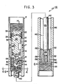
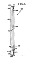
- the Figures 3-6 illustrate the firing heads 10, 10' in greater detail.
- the firing heads 10, 10' are referred to jointly as firing head 10.
- the firing head 10 thereof includes an upper sub-assembly or sub 12 having an upper set of threads 14 for coupling the firing head 10 to a tubing string for lowering into a well.
- Upper sub 12 has a reduced diameter, lower portion 16 forming a pin threadedly coupled to a housing 18 and sealed there against by a pair of 0-rings 17. Housing 18 is threaded at a lower portion 20 thereof for coupling the firing head 10 to a perforating gun or other downhole explosive device.
- sub 12 is normally an upper sub, it will be seen that the firing head 10 can be operated so that sub 12 is disposed below housing 18, as in Figure 1.
- upper sub 12 Immediately beneath the threaded portion 14, upper sub 12 has a relatively large diameter counterbore 22 bounded at its lower extremity by an annular shoulder 24. Beginning at an inner edge of shoulder 24 is a downwardly extending second, relatively smaller diameter counterbore 26 extending through a lower extremity of upper sub 12.
- a piston ram 30 has an upper piston 32 fitting closely against the counterbore 26 of upper sub 12 and having two 0-rings seals 34 providing a fluid tight seal between the piston 32 and the counterbore 26. Piston 32 extends upwardly from counterbore 26 and is spaced concentrically from counterbore 22.
- An annularly shaped piston retainer 34 is fitted within and threadedly coupled to the counterbore 22 and is prevented from moving downwardly within upper sub 12 by the shoulder 24.
- Retainer 34 has an inner surface dimensioned to fit closely against the outer surface of the piston 32.
- six shear pins 36 couple the piston ram 30 to the piston retainer 34 to restrain the piston ram 30 against movement downwardly with respect to upper sub 12 until such time as a sufficient pressure differential is applied across the piston of piston ram 30 to shear the pins 36.
- Piston ram 30 also includes a downwardly extending, reduced diameter projection 40 having a plurality of radially extending fins 42 which serve in part to center the projection 40 in the counterbore 36. Fins 42 also limit the downward travel of ram 30, as described more fully below.
- a generally cylindrical upper plug 44 is threadedly reatined within a counterbore 46 of the housing 18.
- Upper plug 44 has a pair of 0-ring seals 48 forming a fluid tight seal with the hosuing 18 at the counterbore 46.
- Upper plug 44 has a first concentric relatively large diameter counterbore 50 extending from an opening in an upper surface of the counterbore 44 downwardly to an inwardly extending shoulder 52. Extending downwardly from an inner extremity of the shoulder 52 is a second relatively smaller diameter concentric counterbore 54 which terminates at a shoulder 56.
- a third counterbore 58 Extending downwardly from an inner extremity of shoulder 56 is a third counterbore 58 having yet a smaller diameter Extending from the counterbore 58 through the lower extremity of upper plug 44 is a relatively small concentric cylindrical opening 60.
- the lower extremity of opening 60 is hermetically sealed by a circular stainless steel closure disk 62 spot welded to the upper plug 44..
- a firing pin 66 is held within the counterbore 50 and above the- counterbore 54 by a shear pin 68.
- Firing pin 66 has an upper surface 70 positioned to receive the impact of projection 40 of piston ram 30 in order to force the firing pin 66 downwardly within counterbore 50 of upper plug 44.
- a lower potion of firing pin 66 is formed as a relatively narrow projection 72 which impacts against a percussion primer assembly 100 when the firing pin 66 is forced downwardly from counterbore 50.
- Assembly 100 is held within counterbore 58 by a primer retainer 102 which is threaded into counterbore 54.
- Retainer 102 has a concentric opening therethrough shaped to receive the lower portion of firing pin 66 and guide the projection 72 into engagement with the primer assembly 100.
- the firing pin 66 has a number of depressions 104 in an outer surface of its upper, relatively large diameter portion to permit air beneath firing pin 66 to flow upwardly past it as firing pin 66 moves downwardly.
- the percussion primer assembly 100 includes a generally cylindrical primer cup 102 having an upper flat surafec 104 and a lower flat surafec 106.
- the surface 106 has a concentric, cylindrical bore 108 formed therethrough toward surface 104.
- a concentric, cylindrical counterbore 100 alos is formed in cup 102 from an upper boundary of bore 108 and terminating a short distance from surface 104, thus to form a thin wall 112 therebetween.
- Counterbore 110 forms an annular shoulder 114 at the upper boundary of bore 108.
- Primer cup 102 may be made, for example, of stainless steel.
- Counterbore 110 is filled with a primer mix 116, described in greater detail below.
- a stainless steel closure disc 118 is positioned against should 114 to retain the primer mix 116 in counterbore 110.
- Disc 118 is pressed upwardly against shoulder 114 by a cylindrically shaped stainless steel anvil 120 positioned within bore 108.
- a lower surface 122 of anvil 120 is flush with surface 106.
- a second stainless steel closure disc 124 is spot welded to surface 106 to support the anvil 120 wihin cup 102 and to provide a hermetic seal to protect the primer mix 116 against moisture as well as gases produced by other pyrotechnic material in the device 10.
- the primer mix 116 is a pyrotechnic mixture of titanium and potassium perchlorate mixed in a weight ratio of 41% titanium to 59% potassium perchlorate.
- the titanium is provided in powdered form with particles ranging from 1 to 3 microns in diameter and the potassium perchlorate is provided in powdered form with particles less than 10 microns in diameter.
- the thickness of the web 112 and the depth of the counterbore 110, together with the compaction of the primer mix 116, are selected to achieve the desired impact sensitivity. That is, as the thickness of web 112 is increased, impact sensitivity of the primer mix 116 in the assembly 100 is decreased, and as the depth of counterbore 110 is increased, so likewise is the impact sensitivity decreased. Moreover, as the density of the primer mix is increased (by increasing the compaction pressure), so also is the impact sensitivity lowered. In the disclosed embodiment, the thickness of the web 112 is nominally 0.011 inch (0.28mm) thick and the depth of the counterbore 110 is nominally 0.035 inch (0.89mm) deep. Where the primer mix is compacted from 68% to 81% of crystal density in this housing, an impact sensitivity in excess of 4 ft lbf (5.4J) can be achieved and often is.
- the projection 72 of firing pin 66 impacts the web 112 to deform it inwardly, thus forcing the primer mix 116 against the anvil 120 to ignite it.
- Web 112 is made sufficiently thin so that it will be deformed adequately by the impact of the projection to ensure ignition.
- the hot gases thus produced shatter the thin closure disc 118.
- Anvil 120 is provided with four longitudinally extending openings 128 therethrough which then form four jets of hot ignition gas and steel particles from disc 118. These jets of gas then burst through disc 1-24 to provide a means of igniting a flash sensitive, first fire mix, such as AlA.
- a lower plug 130 is threadedly received within a counterbore 132 of the lower portion 20 of housing 18.
- Lower plug 130 has a central aperture 134 therethrough with a threaded lower portion.
- An elongate, generally cylindrical delay element assembly 136 is threaded at a reduced diameter lower portion 138 thereof.
- Portion 138 of assembly 136 is threaded into the aperture 134 so that a lower surface of portion 138 is flush with a lower surface 140 of plug 130.
- An uuper relatively larger diameter portion 142 of assembly 136 extends upwardly from plug 130.
- An upper surface 144 of portion 142 is disposed adjacent aperture 60 of upper plug 44.
- Housing 18 has a further counterbore 146 spaced from upper portion 142 of assembly 136 to define a plenum chamber therebetween.
- the jet of gases and hot particles emitted through aperture 60 by primer assembly 100 in response to the impact of projection 72 of firing pin 66 acts as a signal to initiate a combustive reaction within assembly 136.
- This combustive reaction proceeds for a period of time sufficient to permit an operator at the wellhead, if so desired, to reduce the pressure in the well to a lower value desired at the time that the perforating guns are detonated by the firing head 10.
- a detonation initiator adjacent the lower end of portion 138 detonates a detonating cord (not shown) coupled to the lower end of portion 138 in order to detonate the guns.
- combustion gas exits .from assembly 136 and fills the plen ⁇ m chamber.
- Lower plug 130 is provided with a plurality of vent apertures 150 therethrough and sealed at their upper ends by closure discs 152.
- closure discs 152 As the combustion gases accumulate within the plenum chamber, they build up a slight pressure differential across the closure discs 152, causing them to rupture and permit the gases to pass downwardly through the apertures 150 so that the gases vent into the gun carriers coupled with the lower portion 20 of housing 18. Since the interior of the firing head 10 below the piston 32 of the piston ram 30 is sealed against fluid pressure and the gun carrier likewise is sealed against fluid pressure, the pressure within the plenum chamber will remain essentially at one atmosphere. In addition, the venting of the combustion gases dissipates heat from the assembly 136. Accordingly, the principal factor in determining the length of the delay provided by the delay element assembly 136 is the downhole ambient temperature.
- delay element assembly 136 includes a generally cylindrical housing 160 having a central cylindrical aperture 162.
- a cylindrical pellet 164 of AlA first fire mix is positioned within aperture 162 so that an upper surface of pellet 164 is flush with the surface 144 of assembly 136 and extends downwardly a short distance therefrom.
- Aperture 162 is closed at surface 144 by an adhesive high temperature closure disc 166.
- a succession of tungston delay composition discs 168 are positioned within apertures 162 to extend from pellet 164 downwardly to a point within aperture 162 approximately half way through the extent of aperture 162 through lower portion 138.
- 55 tungston composition discs (mil-T-23132) were utilized, each disc having 500 milligrams of composition compressed at 30,000 psi (210 MN/m 2 ) and forming a column approximately 10 inches (250mm) high.
- a second pellet of AlA 170 Positioned within the aperture 162 immediately below the lowermost tungston disc 168 is a second pellet of AlA 170. Immediately below the pellet 170 is a pellet of a titanium/potassium perchlorate flash charge 172. Immediately below the pellet 172 is a detonator having an upper booster 174 of lead azide (RD-1333) and a lower high explosive output charge 176 which may be either PYX or HNS-II. Aperture 162 is closed at its lower end by a closure disc 178 spot welded to the housing 160.
- the last tungston delay element 168 When the last tungston delay element 168 has burned through, it ignites the AlA charge 170 which in turn ignites the charge 172 which serves to provide a deflagrating output to the booster 174 which in turn detonates the high explosive output charge 176. This detonation is transferred to the detonating cord of the perforating guns to cause them to fire, and may thus be regarded as an explosive actuation signal.
- the firing head 196 preferably includes a percussion type primer including primer mix 116, described above.
- the primer detonates a primary high explosive, such as lead azide which in turn detonates a secondary high explosive, such as PYX or HNS-II; the output from the secondary high explosives serves to initiate the detonation of the detonating cord at the respective end thereof by detonating an appropriate booster thereat.
- Firing head 196 also preferably includes an annular space extending circumferentially about its firing pin and downwardly therefrom, so that particles and debris settling out from well fluids can collect in the annular space below the firing pin without interferring with its operation.
- boosters typically are utilized to couple the detonation of one cord to the next.
- non-directional boosters including a single secondary high explosive which acts both as an acceptor and donor are employed.
- the high explosive can cup of guilding metal, stainless steel or aluminium, or PYX compacted to a density of 1.455 gm/cm in such a cup. An open end, of the cup is then crimped over the end of the detonating cord.
- detonation initiators may be utilized in the present invention.
- one or both of the initiators may be electrically actuated initiators.
Landscapes
- Engineering & Computer Science (AREA)
- Life Sciences & Earth Sciences (AREA)
- Geology (AREA)
- Mining & Mineral Resources (AREA)
- Physics & Mathematics (AREA)
- Environmental & Geological Engineering (AREA)
- Fluid Mechanics (AREA)
- General Life Sciences & Earth Sciences (AREA)
- Geochemistry & Mineralogy (AREA)
- General Engineering & Computer Science (AREA)
- Portable Nailing Machines And Staplers (AREA)
- Preparation Of Compounds By Using Micro-Organisms (AREA)
Applications Claiming Priority (2)
| Application Number | Priority Date | Filing Date | Title |
|---|---|---|---|
| US06/587,340 US4632034A (en) | 1984-03-08 | 1984-03-08 | Redundant detonation initiators for use in wells and method of use |
| US587340 | 1984-03-08 |
Publications (3)
| Publication Number | Publication Date |
|---|---|
| EP0154532A2 true EP0154532A2 (de) | 1985-09-11 |
| EP0154532A3 EP0154532A3 (en) | 1986-04-02 |
| EP0154532B1 EP0154532B1 (de) | 1987-09-09 |
Family
ID=24349408
Family Applications (1)
| Application Number | Title | Priority Date | Filing Date |
|---|---|---|---|
| EP85301429A Expired EP0154532B1 (de) | 1984-03-08 | 1985-03-01 | Hochexplosive Vorrichtungen zur Anwendung in Bohrlöchern und Verfahren zur Detonation derselben |
Country Status (5)
| Country | Link |
|---|---|
| US (1) | US4632034A (de) |
| EP (1) | EP0154532B1 (de) |
| AU (1) | AU571660B2 (de) |
| CA (1) | CA1235059A (de) |
| NO (1) | NO164558C (de) |
Cited By (4)
| Publication number | Priority date | Publication date | Assignee | Title |
|---|---|---|---|---|
| GB2194316A (en) * | 1986-08-11 | 1988-03-02 | Dresser Ind | Method and apparatus for firing borehole perforating apparatus |
| EP0703348A3 (de) * | 1994-08-31 | 1996-12-11 | Halliburton Co | Vorrichtung zum Verbinden von Perforatoren im Bohrloch |
| WO2017194219A1 (en) * | 2016-05-09 | 2017-11-16 | Dynaenergetics Gmbh & Co. Kg | High temperature initiator |
| EP3527929A1 (de) * | 2018-02-15 | 2019-08-21 | Goodrich Corporation | Zündmechanismus für sekundärsprengstoff |
Families Citing this family (42)
| Publication number | Priority date | Publication date | Assignee | Title |
|---|---|---|---|---|
| US4901802A (en) * | 1987-04-20 | 1990-02-20 | George Flint R | Method and apparatus for perforating formations in response to tubing pressure |
| US4953464A (en) * | 1987-07-13 | 1990-09-04 | Atlas Powder Company | Multi-directional signal transmission in a blast initiation system |
| US4821645A (en) * | 1987-07-13 | 1989-04-18 | Atlas Powder Company | Multi-directional signal transmission in a blast initiation system |
| US4762067A (en) * | 1987-11-13 | 1988-08-09 | Halliburton Company | Downhole perforating method and apparatus using secondary explosive detonators |
| US4911251A (en) * | 1987-12-03 | 1990-03-27 | Halliburton Company | Method and apparatus for actuating a tubing conveyed perforating gun |
| US4836109A (en) * | 1988-09-20 | 1989-06-06 | Halliburton Company | Control line differential firing head |
| US5007344A (en) * | 1988-12-01 | 1991-04-16 | Dresser Industries, Inc. | Dual firing system for a perforating gun |
| US5088413A (en) * | 1990-09-24 | 1992-02-18 | Schlumberger Technology Corporation | Method and apparatus for safe transport handling arming and firing of perforating guns using a bubble activated detonator |
| US5161616A (en) * | 1991-05-22 | 1992-11-10 | Dresser Industries, Inc. | Differential firing head and method of operation thereof |
| US5148868A (en) * | 1991-08-12 | 1992-09-22 | Christian J B | Method and apparatus for perforating tubing |
| US5417162A (en) * | 1993-07-01 | 1995-05-23 | The Ensign-Bickford Company | Detonation coupling device |
| US5444598A (en) * | 1993-09-29 | 1995-08-22 | Raymond Engineering Inc. | Capacitor exploding foil initiator device |
| US5436791A (en) * | 1993-09-29 | 1995-07-25 | Raymond Engineering Inc. | Perforating gun using an electrical safe arm device and a capacitor exploding foil initiator device |
| US5551520A (en) * | 1995-07-12 | 1996-09-03 | Western Atlas International, Inc. | Dual redundant detonating system for oil well perforators |
| WO1997006402A2 (en) * | 1995-08-04 | 1997-02-20 | Bolinas Technologies, Inc. | Controlled small-charge blasting by explosive |
| US5603384A (en) * | 1995-10-11 | 1997-02-18 | Western Atlas International, Inc. | Universal perforating gun firing head |
| US6327978B1 (en) | 1995-12-08 | 2001-12-11 | Kaman Aerospace Corporation | Exploding thin film bridge fracturing fragment detonator |
| CA2230574C (en) * | 1997-02-26 | 2005-12-20 | Alliant Techsystems Inc. | Through bulkhead initiator |
| AUPP021697A0 (en) | 1997-11-06 | 1997-11-27 | Rocktek Limited | Radio detonation system |
| US6752083B1 (en) | 1998-09-24 | 2004-06-22 | Schlumberger Technology Corporation | Detonators for use with explosive devices |
| US6385031B1 (en) | 1998-09-24 | 2002-05-07 | Schlumberger Technology Corporation | Switches for use in tools |
| US6283227B1 (en) | 1998-10-27 | 2001-09-04 | Schlumberger Technology Corporation | Downhole activation system that assigns and retrieves identifiers |
| US6938689B2 (en) | 1998-10-27 | 2005-09-06 | Schumberger Technology Corp. | Communicating with a tool |
| US7347278B2 (en) * | 1998-10-27 | 2008-03-25 | Schlumberger Technology Corporation | Secure activation of a downhole device |
| US7383882B2 (en) | 1998-10-27 | 2008-06-10 | Schlumberger Technology Corporation | Interactive and/or secure activation of a tool |
| US6148263A (en) * | 1998-10-27 | 2000-11-14 | Schlumberger Technology Corporation | Activation of well tools |
| RU2160829C2 (ru) * | 1998-12-30 | 2000-12-20 | Шакиров Рустам Анисович | Устройство для инициирования детонации в перфораторах, опускаемых в скважину на насосно-компрессорных трубах |
| US6173772B1 (en) * | 1999-04-22 | 2001-01-16 | Schlumberger Technology Corporation | Controlling multiple downhole tools |
| FR2812937B1 (fr) * | 2000-08-14 | 2005-03-04 | Denel Proprietary Ltd | Dispositif d'amorcage amplificateur de force pour cartouche |
| US6550538B1 (en) | 2000-11-21 | 2003-04-22 | Schlumberger Technology Corporation | Communication with a downhole tool |
| US20050183610A1 (en) * | 2003-09-05 | 2005-08-25 | Barton John A. | High pressure exposed detonating cord detonator system |
| RU2274733C1 (ru) * | 2004-08-10 | 2006-04-20 | Закрытое акционерное общество "Пермский инженерно-технический центр "Геофизика" | Адиабатический воспламенитель скважинных зарядов |
| RU2272895C1 (ru) * | 2004-08-10 | 2006-03-27 | Рустам Анисович Шакиров | Устройство для возбуждения детонации в скважинных перфораторах (варианты) |
| RU2274734C1 (ru) * | 2004-10-19 | 2006-04-20 | Федеральное государственное унитарное предприятие "Российский Федеральный ядерный центр - Всероссийский научно-исследовательский институт экспериментальной физики" (ФГУП "РФЯЦ - ВНИИЭФ") | Взрыватель для скважинной аппаратуры |
| US7600562B2 (en) * | 2008-02-22 | 2009-10-13 | Christian J B | Non-explosive tubing perforator and method of perforating |
| RU2489567C1 (ru) * | 2012-01-11 | 2013-08-10 | Федеральное Государственное унитарное предприятие "Российский Федеральный ядерный центр - Всероссийский научно-исследовательский институт экспериментальной физики - ФГУП "РФЯЦ-ВНИИЭФ" | Взрыватель для прострелочно-взрывной аппаратуры |
| WO2014123508A1 (en) * | 2013-02-05 | 2014-08-14 | Halliburton Energy Energy Services, Inc. | An initiator having an explosive substance of a secondary explosive |
| USD719236S1 (en) * | 2013-04-03 | 2014-12-09 | Orica International Pte Ltd | Housing assembly for a perimeter blasting device |
| WO2016036357A1 (en) * | 2014-09-03 | 2016-03-10 | Halliburton Energy Services, Inc. | Perforating systems with insensitive high explosive |
| WO2016036358A1 (en) * | 2014-09-03 | 2016-03-10 | Halliburton Energy Services, Inc. | Perforating systems with insensitive high explosive |
| RU2612170C1 (ru) * | 2015-12-29 | 2017-03-02 | Общество с ограниченной ответственностью "Промперфоратор" | Устройство для возбуждения детонации в скважинных кумулятивных перфораторах |
| WO2020032936A1 (en) * | 2018-08-07 | 2020-02-13 | Halliburton Energy Services, Inc. | System and method for firing a charge in a well tool |
Family Cites Families (15)
| Publication number | Priority date | Publication date | Assignee | Title |
|---|---|---|---|---|
| US2475875A (en) * | 1943-08-07 | 1949-07-12 | Du Pont | Explosive assembly |
| US2595615A (en) * | 1948-03-02 | 1952-05-06 | William G Sweetman | Initiating device for suspended explosive charges |
| US2707439A (en) * | 1954-05-26 | 1955-05-03 | Canadian Ind 1954 Ltd | Short interval delay blasting device |
| US3174545A (en) * | 1958-01-13 | 1965-03-23 | Petroleum Tool Res Inc | Method of stimulating well production by explosive-induced hydraulic fracturing of productive formation |
| US3353458A (en) * | 1964-12-04 | 1967-11-21 | Albert D Johnson | Apparatus for stripping die cut blanks |
| US3353485A (en) * | 1965-12-29 | 1967-11-21 | Du Pont | Bidirectional delay connector |
| US3618522A (en) * | 1969-09-29 | 1971-11-09 | Hamilton Watch Co | Dual safety grenade fuze |
| AT321160B (de) * | 1969-10-01 | 1975-03-25 | Urbach Ing Erich | Nebelwurfkörper |
| US3727552A (en) * | 1971-06-04 | 1973-04-17 | Du Pont | Bidirectional delay connector |
| US3762267A (en) * | 1972-06-26 | 1973-10-02 | Us Army | Miniature initiator assembly |
| GB1565004A (en) * | 1977-04-18 | 1980-04-16 | Weatherford Dmc | Chemical cutting appratus and method for use in wells |
| US4208966A (en) * | 1978-02-21 | 1980-06-24 | Schlumberger Technology Corporation | Methods and apparatus for selectively operating multi-charge well bore guns |
| AU524959B2 (en) * | 1979-01-18 | 1982-10-14 | Aeci Limited | Sequential firing system for explosives |
| US4429741A (en) * | 1981-10-13 | 1984-02-07 | Christensen, Inc. | Self powered downhole tool anchor |
| US4484639A (en) * | 1983-07-25 | 1984-11-27 | Dresser Industries, Inc. | Method and apparatus for perforating subsurface earth formations |
-
1984
- 1984-03-08 US US06/587,340 patent/US4632034A/en not_active Expired - Lifetime
-
1985
- 1985-02-28 CA CA000475502A patent/CA1235059A/en not_active Expired
- 1985-03-01 EP EP85301429A patent/EP0154532B1/de not_active Expired
- 1985-03-07 NO NO850909A patent/NO164558C/no unknown
- 1985-03-07 AU AU39694/85A patent/AU571660B2/en not_active Ceased
Cited By (10)
| Publication number | Priority date | Publication date | Assignee | Title |
|---|---|---|---|---|
| GB2194316A (en) * | 1986-08-11 | 1988-03-02 | Dresser Ind | Method and apparatus for firing borehole perforating apparatus |
| US4770246A (en) * | 1986-08-11 | 1988-09-13 | Dresser Industries, Inc. | Method and apparatus for firing borehole perforating apparatus |
| GB2194316B (en) * | 1986-08-11 | 1990-03-28 | Dresser Ind | Method and apparatus for firing borehole perforating apparatus |
| EP0703348A3 (de) * | 1994-08-31 | 1996-12-11 | Halliburton Co | Vorrichtung zum Verbinden von Perforatoren im Bohrloch |
| WO2017194219A1 (en) * | 2016-05-09 | 2017-11-16 | Dynaenergetics Gmbh & Co. Kg | High temperature initiator |
| GB2570976A (en) * | 2016-05-09 | 2019-08-14 | Dynaenergetics Gmbh & Co Kg | High temperature initiator |
| RU2699145C1 (ru) * | 2016-05-09 | 2019-09-03 | Динаэнергетикс Гмбх Унд Ко. Кг | Высокотемпературный взрыватель |
| US10899680B2 (en) | 2016-05-09 | 2021-01-26 | DynaEnergetics Europe GmbH | High temperature initiator |
| EP3527929A1 (de) * | 2018-02-15 | 2019-08-21 | Goodrich Corporation | Zündmechanismus für sekundärsprengstoff |
| US10837747B2 (en) | 2018-02-15 | 2020-11-17 | Goodrich Corporation | High explosive firing mechanism |
Also Published As
| Publication number | Publication date |
|---|---|
| EP0154532B1 (de) | 1987-09-09 |
| AU571660B2 (en) | 1988-04-21 |
| NO850909L (no) | 1985-09-09 |
| US4632034A (en) | 1986-12-30 |
| NO164558C (no) | 1990-10-17 |
| AU3969485A (en) | 1985-09-12 |
| EP0154532A3 (en) | 1986-04-02 |
| NO164558B (no) | 1990-07-09 |
| CA1235059A (en) | 1988-04-12 |
Similar Documents
| Publication | Publication Date | Title |
|---|---|---|
| EP0154532B1 (de) | Hochexplosive Vorrichtungen zur Anwendung in Bohrlöchern und Verfahren zur Detonation derselben | |
| US4614156A (en) | Pressure responsive explosion initiator with time delay and method of use | |
| EP2401474B1 (de) | Neuartige vorrichtung und verfahren zum abfeuern von perforationspistolen | |
| US5551520A (en) | Dual redundant detonating system for oil well perforators | |
| US5046567A (en) | Adiabatically induced ignition of combustible materials | |
| US5062485A (en) | Variable time delay firing head | |
| EP0721051B1 (de) | Auslösen eines Zündkopfs | |
| AU665144B2 (en) | Air chamber actuator for a perforating gun | |
| US6009947A (en) | Casing conveyed perforator | |
| EP0585142B1 (de) | Vorrichtung zur selektiven Perforierung mehrerer Horizonte in einem Bohrloch | |
| AU4979999A (en) | Full bore gun system | |
| CA2133818A1 (en) | Combined pressure testing and selective fired perforating systems | |
| US5632348A (en) | Fluid activated detonating system | |
| JPH03119290A (ja) | 時間遅延穿孔装置 | |
| EP0155128B1 (de) | Vorrichtung zum Betätigen von explosiven Ladungen in einem Bohrloch und Bohrlochdurchlöcherungsverfahren | |
| US6095258A (en) | Pressure actuated safety switch for oil well perforating | |
| US5386780A (en) | Method and apparatus for extended time delay of the detonation of a downhole explosive assembly | |
| US4484639A (en) | Method and apparatus for perforating subsurface earth formations | |
| CA2172047C (en) | Method and apparatus for downhole activated wellbore completion | |
| WO1995009965A1 (en) | Casing conveyed flowports for borehole use | |
| US3491841A (en) | Method and apparatus for the explosive drilling of boreholes | |
| US7546805B2 (en) | Detonator | |
| CA2172046C (en) | Fluid activated detonating system |
Legal Events
| Date | Code | Title | Description |
|---|---|---|---|
| PUAI | Public reference made under article 153(3) epc to a published international application that has entered the european phase |
Free format text: ORIGINAL CODE: 0009012 |
|
| AK | Designated contracting states |
Designated state(s): GB NL |
|
| PUAL | Search report despatched |
Free format text: ORIGINAL CODE: 0009013 |
|
| AK | Designated contracting states |
Kind code of ref document: A3 Designated state(s): GB NL |
|
| 17P | Request for examination filed |
Effective date: 19860315 |
|
| RAP1 | Party data changed (applicant data changed or rights of an application transferred) |
Owner name: HALLIBURTON COMPANY |
|
| 17Q | First examination report despatched |
Effective date: 19861128 |
|
| GRAA | (expected) grant |
Free format text: ORIGINAL CODE: 0009210 |
|
| AK | Designated contracting states |
Kind code of ref document: B1 Designated state(s): GB NL |
|
| PLBE | No opposition filed within time limit |
Free format text: ORIGINAL CODE: 0009261 |
|
| STAA | Information on the status of an ep patent application or granted ep patent |
Free format text: STATUS: NO OPPOSITION FILED WITHIN TIME LIMIT |
|
| 26N | No opposition filed | ||
| PGFP | Annual fee paid to national office [announced via postgrant information from national office to epo] |
Ref country code: NL Payment date: 19950331 Year of fee payment: 11 |
|
| PGFP | Annual fee paid to national office [announced via postgrant information from national office to epo] |
Ref country code: GB Payment date: 19960221 Year of fee payment: 12 |
|
| PG25 | Lapsed in a contracting state [announced via postgrant information from national office to epo] |
Ref country code: NL Effective date: 19961001 |
|
| NLV4 | Nl: lapsed or anulled due to non-payment of the annual fee |
Effective date: 19961001 |
|
| PG25 | Lapsed in a contracting state [announced via postgrant information from national office to epo] |
Ref country code: GB Effective date: 19970301 |
|
| GBPC | Gb: european patent ceased through non-payment of renewal fee |
Effective date: 19970301 |