EP0154607A2 - Dispositif pour maintenir une pièce dans une position spatiale - Google Patents
Dispositif pour maintenir une pièce dans une position spatiale Download PDFInfo
- Publication number
- EP0154607A2 EP0154607A2 EP85810098A EP85810098A EP0154607A2 EP 0154607 A2 EP0154607 A2 EP 0154607A2 EP 85810098 A EP85810098 A EP 85810098A EP 85810098 A EP85810098 A EP 85810098A EP 0154607 A2 EP0154607 A2 EP 0154607A2
- Authority
- EP
- European Patent Office
- Prior art keywords
- pallet
- plate
- channels
- workpiece
- plates
- Prior art date
- Legal status (The legal status is an assumption and is not a legal conclusion. Google has not performed a legal analysis and makes no representation as to the accuracy of the status listed.)
- Granted
Links
Images


Classifications
-
- B—PERFORMING OPERATIONS; TRANSPORTING
- B23—MACHINE TOOLS; METAL-WORKING NOT OTHERWISE PROVIDED FOR
- B23Q—DETAILS, COMPONENTS, OR ACCESSORIES FOR MACHINE TOOLS, e.g. ARRANGEMENTS FOR COPYING OR CONTROLLING; MACHINE TOOLS IN GENERAL CHARACTERISED BY THE CONSTRUCTION OF PARTICULAR DETAILS OR COMPONENTS; COMBINATIONS OR ASSOCIATIONS OF METAL-WORKING MACHINES, NOT DIRECTED TO A PARTICULAR RESULT
- B23Q16/00—Equipment for precise positioning of tool or work into particular locations not otherwise provided for
- B23Q16/001—Stops, cams, or holders therefor
-
- B—PERFORMING OPERATIONS; TRANSPORTING
- B23—MACHINE TOOLS; METAL-WORKING NOT OTHERWISE PROVIDED FOR
- B23Q—DETAILS, COMPONENTS, OR ACCESSORIES FOR MACHINE TOOLS, e.g. ARRANGEMENTS FOR COPYING OR CONTROLLING; MACHINE TOOLS IN GENERAL CHARACTERISED BY THE CONSTRUCTION OF PARTICULAR DETAILS OR COMPONENTS; COMBINATIONS OR ASSOCIATIONS OF METAL-WORKING MACHINES, NOT DIRECTED TO A PARTICULAR RESULT
- B23Q1/00—Members which are comprised in the general build-up of a form of machine, particularly relatively large fixed members
- B23Q1/03—Stationary work or tool supports
-
- B—PERFORMING OPERATIONS; TRANSPORTING
- B23—MACHINE TOOLS; METAL-WORKING NOT OTHERWISE PROVIDED FOR
- B23Q—DETAILS, COMPONENTS, OR ACCESSORIES FOR MACHINE TOOLS, e.g. ARRANGEMENTS FOR COPYING OR CONTROLLING; MACHINE TOOLS IN GENERAL CHARACTERISED BY THE CONSTRUCTION OF PARTICULAR DETAILS OR COMPONENTS; COMBINATIONS OR ASSOCIATIONS OF METAL-WORKING MACHINES, NOT DIRECTED TO A PARTICULAR RESULT
- B23Q1/00—Members which are comprised in the general build-up of a form of machine, particularly relatively large fixed members
- B23Q1/25—Movable or adjustable work or tool supports
- B23Q1/44—Movable or adjustable work or tool supports using particular mechanisms
- B23Q1/50—Movable or adjustable work or tool supports using particular mechanisms with rotating pairs only, the rotating pairs being the first two elements of the mechanism
- B23Q1/54—Movable or adjustable work or tool supports using particular mechanisms with rotating pairs only, the rotating pairs being the first two elements of the mechanism two rotating pairs only
- B23Q1/5406—Movable or adjustable work or tool supports using particular mechanisms with rotating pairs only, the rotating pairs being the first two elements of the mechanism two rotating pairs only a single rotating pair followed perpendicularly by a single rotating pair
- B23Q1/5443—Movable or adjustable work or tool supports using particular mechanisms with rotating pairs only, the rotating pairs being the first two elements of the mechanism two rotating pairs only a single rotating pair followed perpendicularly by a single rotating pair and in which the degree of freedom, which belongs to the working surface, is parallel to this surface
-
- B—PERFORMING OPERATIONS; TRANSPORTING
- B23—MACHINE TOOLS; METAL-WORKING NOT OTHERWISE PROVIDED FOR
- B23Q—DETAILS, COMPONENTS, OR ACCESSORIES FOR MACHINE TOOLS, e.g. ARRANGEMENTS FOR COPYING OR CONTROLLING; MACHINE TOOLS IN GENERAL CHARACTERISED BY THE CONSTRUCTION OF PARTICULAR DETAILS OR COMPONENTS; COMBINATIONS OR ASSOCIATIONS OF METAL-WORKING MACHINES, NOT DIRECTED TO A PARTICULAR RESULT
- B23Q11/00—Accessories fitted to machine tools for keeping tools or parts of the machine in good working condition or for cooling work; Safety devices specially combined with or arranged in, or specially adapted for use in connection with, machine tools
- B23Q11/10—Arrangements for cooling or lubricating tools or work
-
- Y—GENERAL TAGGING OF NEW TECHNOLOGICAL DEVELOPMENTS; GENERAL TAGGING OF CROSS-SECTIONAL TECHNOLOGIES SPANNING OVER SEVERAL SECTIONS OF THE IPC; TECHNICAL SUBJECTS COVERED BY FORMER USPC CROSS-REFERENCE ART COLLECTIONS [XRACs] AND DIGESTS
- Y10—TECHNICAL SUBJECTS COVERED BY FORMER USPC
- Y10S—TECHNICAL SUBJECTS COVERED BY FORMER USPC CROSS-REFERENCE ART COLLECTIONS [XRACs] AND DIGESTS
- Y10S269/00—Work holders
- Y10S269/90—Supporting structure having work holder receiving apertures or projections
Definitions
- the present invention relates to a device for holding an object in a spatial position, with a pallet on which the object can be attached.
- Devices for holding objects which have a pallet on which the object, for example a workpiece, can be fastened.
- the workpiece to be machined, which is on the pallet can be brought into the position required for machining it on a presetting station. Then the workpiece, including the pallet, is inserted into the working area of the machine while maintaining the set position.
- measuring devices For an exact setting of the workpiece in a horizontal plane, measuring devices are required which are very precise in the two directions X and Y of the horizontal plane. Adjusting the workpiece on the plane is much more complex because a cross slide system, for example, is required for this. Such horizontal measuring devices are very expensive.
- the object of the present invention is to disclose a mounting device in which the disadvantages mentioned do not occur.
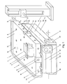
- the device for holding an object in a spatial position has a pallet presetting structure 1, which is located on a presetting station 2 for a processing machine. It can be a machine that processes the workpiece by electrical discharge machining, machining, etc.
- the presetting structure 1 there is a pallet 3 on which the workpiece 4 can be fastened.
- the workpiece 4 is shown only schematically in FIG. 1. This can be fastened, for example, with the aid of a tensioning device 5 resting thereon, through which screws 6 pass.
- a tensioning device 5 resting thereon, through which screws 6 pass.
- threaded openings 8 are made, into which the screws 6 are screwed.
- stops 10 Two of the side surfaces 9 of the pallet body 7 are provided with stops 10 for workpieces 4. These stops 10 are designed as strips and are fastened to the pallet body 7 with the aid of screws (not shown). The screws mentioned are screwed into threaded openings 11 which are made in the side surfaces 9 of the pallet body 7. As can be seen from FIG. 2, the inside of the stop bar 10 can be provided with an undercut 12, in which a possible burr can find space on the workpiece. However, the stops 10 can also be designed as short stop pieces, such as this 7 can be seen.
- Two side surfaces 9 of the pallet body 7 are provided with handles 13 which facilitate the handling of the pallet 3.
- the edge parts of the pallet body 7 are provided with means 14 and 15 which enable the pallet 3 to be fastened to the plate structure 1. These means 14 and 15 will be described in more detail below.
- the presetting structure 1 contains a base plate 20 which is set up on the presetting station 2. On the base plate 20 there is a second plate 21, which in the example shown can also be referred to as a middle plate. It is in fact possible that the presetting structure 1 has only the base plate 20 and a plate lying thereon. Then a third plate 22 is located on the second plate 21 (FIG. 1), the upper edge part of which is provided with furrows 23. These furrows 23 are carried out in the upper region of all four side walls of the top plate 22.
- the left and the rear lower edge of the pallet 3 is' pulled down and the inside of such an elongated projection 14 is undercut.
- This undercut surface is in engagement with the upper flank of the respective groove 23.
- the undercut projection 14 forms the first of the means for fastening the pallet 3 on the third plate 22.
- a bracket 15, which forms the second link of the said fastening means for the pallet 3, is opposite the respective undercut projection 14.
- the respective bracket 15 is removably embedded in the edge part of the pallet 3 opposite the respective projection 14.
- a screw 24 passes through the bracket 15 and is screwed into the pallet body 7.
- the section of the bracket 15 located under the pallet body 7 is also undercut, so that the bracket 15 is also an inwardly projecting section which may lie in one of the furrows 23 of the third plate 22.
- This type of connection of two objects is known, for example, from European Patent Application No. 83810610.2 by the same applicant, one or more brackets 15 being used.
- the pallet body 7 according to FIG. 1 must have the edge portions 14 projecting below. It would be easier if the pallet body 7 could be a flat plate.
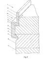
- 2 shows a further embodiment of the first fastening means 14 for the pallet 3, which makes it possible to use a plate without the lower projection for the production of the pallet body 7.
- a bar 25 is attached, which covers the transition point between the pallet body 7 and the upper plate 22.
- an elongated recess 26 is made, in which the lower or left side wall 27 runs obliquely inwards.
- This sloping side wall 27 of the strip 25 fastened in the manner described to the upper plate 22 forms the undercut, projecting part of the fastening means 14, which engages with the upper flank of the groove 23.
- the strip 25 can be fastened to the pallet body 22 with the aid of screws (not shown).
- the upper section of the edge part of the pallet body 7 is provided with a shoulder 34 and with the horizontal flank 28 of this shoulder 34 the second side wall of the recess 26 is engaged in the connecting bar 25.
- the stop bar 10 is fastened in the manner already described with the aid of screws. This ensures that the stop bar 1U is embedded in the pallet 3 and that it does not collide with it whose objects can be made.
- the corner portions of paragraph 27 and the recess 26 are also provided with undercuts 12.
- the second plate 21 is connected to the base plate 20 and to the upper plate 22 by means of hinges 30.
- hinges 30 This enables these three plates 20 to 22 to be at an angle other than zero.
- Such positions of the plates 20 to 22 are shown in FIGS. 3 and 4. 3, the second plate 21 lies on the base plate 20, while the third plate 22 is at an angle alpha of approximately 90 degrees to the second plate 21.
- a connecting strap 40 or another clamping device is provided.
- the end portions of the connecting strap 40 are each provided with a pin 41 - which can be inserted into corresponding openings in the side walls 43 of the plates 21 and 22.
- the distance of these openings from the axis of rotation of the hinges 30 is selected such that, given a distance between the pins 41 and 42 of the connecting bracket 40, the plates 21 and 22 close the desired angle alpha, for example of 90 degrees.
- a vertical measuring column 50 is also indicated, which is placed on the preset 2. It can be a commercially available measuring column which is set up on the work table of a processing machine or a presetting station and which is used to precisely set the distance between the table 2 and a specific point on a workpiece, tool, etc. Such vertical measuring columns are relatively cheap to buy. They can be moved easily on table 2.
- the measuring column has a measuring probe 52 projecting laterally from the measuring column body 51, the height of which, like desired, can be adjusted. At a suitable location, such as in one of the corners of the pallet 3, the latter is provided with a cylindrical pin 54. The lateral surface of this pin 54 serves as the reference surface for the measuring probe 52 on the presetting station and for the tool in the processing machine.
- the pallet 3 has been omitted in FIGS. 3 and 4, the fastening means 14 and 15 of which engage the furrows 23 in the upper plate 22 and thus the pallet 3 in the same inclined position as the upper plate , hold. What is said in the following with respect to the upper plate 22 therefore also applies to the pallet 3.
- axes X and Y which are at right angles to one another are shown. These axes X and Y denote the two main directions in a horizontal plane, and with respect to these axes, the coordinates of the individual points of a workpiece are read and determined in a horizontal plane.
- the axis X is still in a horizontal position.
- the axis Y runs vertically. If you want to bring a point of the workpiece 4 to a very specific point in the Y direction, then you set this distance with an appropriate addition regarding the distance between the lower edge 53 of the plate 22 or the pallet 3 from the presetting station 2 between the probe 52 and the table of preset 2. Thereafter, the probe 52 is brought into the vicinity of the workpiece 4 and moved in the Y direction until the desired point of the workpiece is at the tip of the probe. The workpiece is fixed in this position.
- the position of the Workpiece 4 can also adjust in the second direction X of a horizontal plane, one folds the composite consisting of the upper plate 22 in the folded-up position and the middle plate 21 to the left, as shown in FIG. 4.
- the coordinate system XY is also drawn in the main surface of the upper plate 22. It can be seen from this that after the panel assembly 21 and 22 has been folded over, the X axis now runs vertically. Now, with the help of the vertical measuring column 50, the position of a specific point of the workpiece 4 can also be set in the X direction in the manner described above. After this, the two plates 21 and 22 can be folded back.
- the pallet 3 with the workpiece 4 is removed from the upper plate 22 by loosening the fastening means 14 and 15 and brought into the working area of a processing machine.
- the height of a point of the workpiece 4 can also be set with the aid of the measuring column 50 when it is in its horizontal position, i.e. if the axes X and Y are in a horizontal plane.
- the base plate 20 is connected to the central plate 21 via a first pair of hinges 30, this pair of hinges having an axis A.
- the top plate 22 is connected to the middle plate 21 by means of a further pair of hinges 30, the axis B of this pair of hinges being at right angles to the axis A of the first pair of hinges.
- the hinge 30 contains a hinge plate 31 which is fastened to one of the side walls 43 of the base plate 20 by means of screws 32.
- a bore 33 in which the end part of a bolt 35 is located.
- a recess 36 with a roof-shaped cross section is made, in which the remaining part of the respective bolt 35 lies. This part of the bolts 35 lies on the straight legs of this recess 36 and the bolts 35 are held in place by means of screws 37 which are screwed into the second plate 21.
- one plate has two bolts 35 which are aligned with one another and protrude from the side faces thereof. These bolts 35 form the first half of the hinge 30.
- the plate coupled to such a plate has hinge plates 31 which are fastened to the opposite side surfaces of this plate and which form the second half of the hinge 30.
- the respective hinge plate 31 is at a distance from that side surface 43 of the base plate 20 which runs parallel to the axis A of the hinge pair attached here.
- the edge part 38 of the plate 20 projecting from the hinge plates 31 forms a stop on which the side surface 44 of the plate 21 lying above rests when this plate 21 is in its folded-up position (indicated by dash-dotted lines).
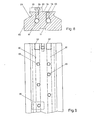
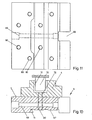
- FIG. 7 shows a machine table 55 with T-grooves 56, on which a base body 60 is fastened in a known manner.
- This base body 60 is elongated and its upper edge part has the furrows 23 already described.
- the pallet 3 which has been described in connection with FIG. 1 and which is held on the furrow body with the aid of the fastening means 14 and 15.
- the openings 8, which have already been discussed in connection with FIG. 1, are made continuously so that they form channels 80 extending between the two main surfaces of the pallet body 7.
- Main channels 61 which run in the longitudinal direction, run in the furrow body 60 and open into the end faces of the furrow body 60. As can be seen from FIG. 9, one of the end parts of these main channels 61 is provided with a thread 62 so that, for example, hoses (not shown) can be connected to supply a cooling or flushing liquid.
- Distribution channels 63 adjoin the main channels 61 and run at an angle, for example at 90 degrees, to the main channels 61. These distribution channels 63 are connected at one end to the main channels 61 in terms of flow and at the other end they open into the upper side 64 of the furrow body 60.
- the pallet channels 80 are designed at points on the pallet 3 such that the pallet channels 80 can be brought into alignment with the distribution channels 63 by simply shifting the pallet 3 along the furrow body 60. This enables the liquid mentioned to be fed through the pallet 3 to the workpiece or tool, the liquid then being able to be guided from the upper mouth of the pallet channels 80 through further hoses with a suitable cross section and of the required number to the work site. This is of great economic importance because the supply hoses etc. can already be attached to the presetting station on the pallet. So far, the corresponding relocation of the feed hoses had to be carried out in the working area of the machine, which is undesirable downtime times of the machine. Mouths 8 of the pallet channels 80, through which no liquid is to be passed and which are nevertheless located above one of the distribution channels, are closed with plugs 58.
- a stop 65 can be attached to a suitable location on the furrow body 60, which stop is held in place by means of a screw 66 that is screwed into one of the distribution channels 63 .
- a relatively small pallet 3 is shown on which the workpiece 4 is attached.
- the underside of the pallet 3 is designed with a groove 67, in which the one side wall is undercut so that it represents the first fastening means 14 for the pallet 3.
- the bracket 15, which represents the second fastening means, is normally arranged in that recess 68 of the pallet body 7, which is designated by 68 in FIG. 11.
- the screw 24, which holds the bracket 15 in this recess 68, is screwed into a transverse hole 69 which is made in the pallet body 7.
- the pallet 3 has a plurality of continuous channels 80 which, as has already been described, can be brought into agreement with the distribution channels 63.
- a depression is indicated approximately in the middle of the workpiece 4, in which the tool 70, for example of an electro-erosion machine, is located.
- Such processing takes place with the supply of a rinsing liquid.
- the workpiece is provided at the bottom with a continuous bore 72, the axis of which coincides with the axis of the pallet channel 8U. The liquid can then be passed directly and easily through the pallet channel 80 and the bore 72 are inserted into the machining zone.
- this base body 60 shows a base body 60 which is plate-shaped. Otherwise, this base body 60 is also provided with the furrows 23 and with the channels, of which only the mouths of some of the distribution channels 63 are shown here.
- a base body 90 is provided with a plurality of bores 91 lying next to one another.
- the shaft of a holder for an object can be inserted into each of these bores 91.
- the base body 90 is provided with further bores 92 and 93, through which fastening screws for the base body 90 can pass.
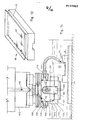
- the gap 71 between the workpiece 4 and the tool 70 can also be supplied with the aid of a flushing device 100 which is attached to the tool holder 101 (FIG. 14).
- the tool holder 101 is exchangeably fastened to the head 102 of a processing machine.
- the tool holder 101 contains a block 103 which is connected to the machine head 102.
- Mainly in the lower part of this block 103 is a horizontally extending opening 104, which extends over the entire width of the block 103.
- a tongue 105 is cut out in the front wall of the block 103 and extends over almost the entire height of the block 103.
- a screw 106 which is screwed into the material of the block 103, passes through the tip of this tongue 105, which is located in the upper half of the block 103.
- a hollow ring 1 ⁇ 8 is attached, which has a C-shaped cross section in the example shown.
- the open side of this ring 108 lies tightly on the outside of block 103.
- a channel 112 is embodied in the interior of the block 103, which leads on the one hand into the interior of the ring 108 and on the other hand into the connection point of the tool holder 101 to the machine head 102.
- In the machine head 102 there is a further channel 113 through which the liquid which is required for the machining of the tool is supplied.
- Said liquid flows from the supply channel 113 through the connecting channel 112 into the interior of the ring 108.
- the liquid is distributed along the entire circumference of the block 103.
- the connection nipples 110 are normally closed. However, where necessary, the hose 111 is connected to the corresponding nipple and the liquid can be led out of the ring and guided to the desired location on the workpiece 4.
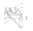
- FIG. 15 shows a further embodiment of the present device.
- This device contains the base plate 20 already discussed here and the plate 21 hinged to it, which in the example shown is in its vertical position.
- This second plate 21 is provided with the furrows 23 already discussed, so that the pallet 3 can be attached to this plate 21.
- a turntable 116 is rotatably mounted, the peripheral part of which is provided with a division 117, to which one or more marks 118 on the pallet 3 are assigned - dividing device.
- the workpiece can be fastened on the turntable 116 in a known manner.
- a further plate 119 can also be fastened on the turntable 116, the side surfaces of which are provided with the furrows 23 already discussed here.
- a pallet can be used to hold the workpiece, which is equipped with the means for engaging in the furrows 23, which have also already been discussed here.
- the workpiece When the second plate is in the up position and when a workpiece is attached to the turntable 116, the workpiece can be sequentially moved e.g. positions shifted by 90 degrees to each other can be brought by rotating the table 116. In these positions, the workpiece can be measured or adjusted in the X and Y directions. Here you can also measure and set a certain angular position of the workpiece, which is different from the horizontal or vertical position.
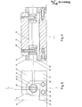
- FIGS. 16 to 18 A further embodiment of the present device is shown in FIGS. 16 to 18.
- the pallet presetting structure 1 has a base body 120, which is connected to a support body 122 via a swivel joint 121, this support body 122 being set up on the table 2.
- the swivel joint 121 can be of a generally known type and therefore this is not described in more detail here.
- the base body 120 is elongated, as can be seen above all from FIGS. 17 and 18.
- the top of the base body 120 has two elongated and parallel projections 123 and 124, the Side walls are provided with furrows 23 already described.
- At least one pallet 3 can be placed on each of the projections 123 and 124 thus formed. In the example shown, however, there is only a single pallet 3 on the base body 120, which, on the other hand, is so wide that it spans the two projections 123 and 124.
- the edge parts of this pallet 3 are provided with the gripping elements 14 and 15 (FIG. 16) already described, which engage with the outer furrows 23 in the projections 123 and 124 of the base body 120.
- the workpiece 4 is fastened in a known manner on the top of the pallet 3.
- the cylindrical pin 54 protrudes from the pallet 3 and indicates the starting point for the machining of the respective workpiece 4.
- a projection 125 protrudes from the underside of the base body 120, the base area of which is square.
- a plurality of square posts 125 can be connected to it, so that different locations of the base body 120 can be coupled to the support body 122.
- the support body 122 is shaped as a cuboid, which is arranged on the table 2 or 55, upright in the example shown.
- One of the edge parts of this cuboid 122 is provided with the swivel joint 121 already mentioned.
- This swivel joint 121 is provided with a locking device 126 which, because it is known, is only indicated schematically in the drawing (FIG. 18).
- the other end part of the joint 121 is rotatably attached to the base body 120 in the middle of the extension 125.
- the base body 120 can not only be pivoted about the joint 121 but also rotated, as is indicated above all in FIG. 17, where the base body 120 is only shown schematically.
- the base body 120 can assume a vertical position on the one hand and a horizontal position on the other hand, as is indicated in FIG. 16.
- the base body 120 can assume layers in between, in which one is designated 1201 and in which it can be rotated around the joint 121.
- the top of the cuboid 122 is provided with recesses 130 and 131 which are spaced apart from one another and in which rigid bodies 132 and 133 with a cylindrical surface are located. These bodies 132 and 133 are held in the recesses 130 and 131 with the aid of screws (not shown) and serve as supports for the base body 120. With the underside 134 of the base body 120, these support bodies 132 and 133 form a line which runs only along a line Contact. The distance between the mentioned support bodies 132 and 133 from the center of the swivel joint 121 is selected such that the side wall 135 of the extension or extension 125 also forms a linear contact with the rollers 132 and 133.
- That side wall of the cuboid 122 which is closer to the swivel joint 1 21, is provided with depressions 136 and 137 in which there are further support bodies 138 and 139. These protrude from the recesses 136 and 137. The distance between these support bodies 138 and 139 from the center of the swivel joint 121 is selected such that the side wall 135 of the extension or extension 125 forms a linear contact with the rollers 138 and 139.
- the base body 1 201 can now be rotated 90 degrees about the joint 121, after which the attachment 125 is again brought into engagement with the lower rollers 138 and 139. Now the workpiece 4 is also rotated by 90 degrees and the position of the workpiece 4 in the Y direction can be set precisely by simply moving it in the vertical direction. It should be clear that the base body 120 can be rotated four times by 90 degrees because the projection 125 has a square outline, as has already been explained. The base body 120 together with the pallet 3 and the workpiece 4 are then pivoted such that they are in a horizontal position, as shown in FIG. 18. Now the position of the workpiece 4 can, if necessary, still be measured in the Z direction.
Landscapes
- Engineering & Computer Science (AREA)
- Mechanical Engineering (AREA)
- Feeding Of Workpieces (AREA)
- Jigs For Machine Tools (AREA)
Applications Claiming Priority (2)
| Application Number | Priority Date | Filing Date | Title |
|---|---|---|---|
| CH1185/84A CH665984A5 (de) | 1984-03-09 | 1984-03-09 | Einrichtung zur halterung eines gegenstandes. |
| CH1185/84 | 1984-03-09 |
Publications (3)
| Publication Number | Publication Date |
|---|---|
| EP0154607A2 true EP0154607A2 (fr) | 1985-09-11 |
| EP0154607A3 EP0154607A3 (en) | 1988-06-01 |
| EP0154607B1 EP0154607B1 (fr) | 1990-08-22 |
Family
ID=4204491
Family Applications (1)
| Application Number | Title | Priority Date | Filing Date |
|---|---|---|---|
| EP85810098A Expired - Lifetime EP0154607B1 (fr) | 1984-03-09 | 1985-03-07 | Dispositif pour maintenir une pièce dans une position spatiale |
Country Status (6)
| Country | Link |
|---|---|
| US (1) | US4880220A (fr) |
| EP (1) | EP0154607B1 (fr) |
| JP (1) | JPS618247A (fr) |
| CH (1) | CH665984A5 (fr) |
| DE (1) | DE3579244D1 (fr) |
| ES (1) | ES541114A0 (fr) |
Families Citing this family (6)
| Publication number | Priority date | Publication date | Assignee | Title |
|---|---|---|---|---|
| SE459456B (sv) * | 1988-05-02 | 1989-07-03 | Ingegerd Dirtoft | Fixtur avsedd foer extremt skakningsfri upplaeggning av objekt |
| CA2074789C (fr) * | 1992-07-28 | 1995-12-05 | Joel W. Jones | Dispositif de transfert pour usinage de precision |
| US20070040314A1 (en) * | 2005-07-12 | 2007-02-22 | Lkt Automation Sdn Bhd | Adjustable tool holder |
| CH711177A1 (fr) * | 2015-06-11 | 2016-12-15 | Watch Out Sa | Système d'usinage de pièces, module de mise au point et procédé d'usinage de pièces. |
| JP6806378B2 (ja) * | 2018-07-06 | 2021-01-06 | Itr井上技研株式会社 | パレット交換治具及びパレット交換治具の着脱方法 |
| US12312223B2 (en) | 2021-06-21 | 2025-05-27 | BendPak, Inc. | Agile mobile scissor lift apparatus |
Family Cites Families (20)
| Publication number | Priority date | Publication date | Assignee | Title |
|---|---|---|---|---|
| US2111299A (en) * | 1937-01-22 | 1938-03-15 | Omer E Robbins | Magnetic sine table |
| US2351773A (en) * | 1941-05-29 | 1944-06-20 | Hans J Lovenston | Device for determining angles |
| US2345708A (en) * | 1942-01-02 | 1944-04-04 | Arthur A Lines | Vise |
| US2353891A (en) * | 1943-03-19 | 1944-07-18 | Anton J Gruntorad | Adjustable work-holding device |
| FR945576A (fr) * | 1947-04-22 | 1949-05-09 | Dispositif permettant les opérations de fraisage sur les tours | |
| FR1020227A (fr) * | 1950-06-15 | 1953-02-03 | Vve H Cullier Et J Bernadou | Perfectionnements aux dispositifs d'arrosage central pour trepans |
| DE1117359B (de) * | 1958-04-16 | 1961-11-16 | Hans Deckel Dr Ing | Aufspanntisch |
| US3499642A (en) * | 1966-11-10 | 1970-03-10 | Harolds Gauges Ltd | Sine tables |
| US3498685A (en) * | 1968-01-18 | 1970-03-03 | Charles A Poplinski | Dovetail slide |
| GB1217741A (en) * | 1968-02-15 | 1970-12-31 | Keith Fulton Scott Thompson | Reusable constructional element for use in constructing jigs, workholders and like fixtures |
| US3726363A (en) * | 1971-06-08 | 1973-04-10 | Twining E | Coolant spider assembly |
| US3893355A (en) * | 1973-12-21 | 1975-07-08 | Giddings & Lewis | Coolant supply system for cutting tools in a machine tool |
| US4020742A (en) * | 1975-12-02 | 1977-05-03 | Raymond Ernest R | Adjustable stop device |
| DE2726731C3 (de) * | 1977-06-14 | 1979-12-13 | Franz 8900 Augsburg Schoeffel | Gerät zum Messen der Höhe eines auf einer Unterlage stehenden Gegenstandes oder zum Anreißen eines solchen Gegenstandes in einer vorgegebenen Höhe |
| GB2099151B (en) * | 1981-02-14 | 1985-09-04 | Lk Tool Co Ltd | Measuring machine |
| JPS57156146A (en) * | 1981-03-16 | 1982-09-27 | Kitamura Kikai Kk | Cooling apparatus for tool of machine tool |
| US4489928A (en) * | 1982-09-16 | 1984-12-25 | Dietrich Otto E | Vise having adjustable features |
| GB2137541A (en) * | 1983-01-18 | 1984-10-10 | Buechler Ag | Guide system for positioning workpieces, e.g. in spark erosion machines |
| CH652061A5 (fr) * | 1983-04-13 | 1985-10-31 | Aciera S A | Palettiseur pour machine-outil. |
| DE8408669U1 (de) * | 1984-03-21 | 1985-03-07 | Fa. Erwin Halder, 7959 Achstetten | Werkstueckpalette, insbesondere fuer bearbeitungszentren |
-
1984
- 1984-03-09 CH CH1185/84A patent/CH665984A5/de not_active IP Right Cessation
-
1985
- 1985-03-07 EP EP85810098A patent/EP0154607B1/fr not_active Expired - Lifetime
- 1985-03-07 DE DE8585810098T patent/DE3579244D1/de not_active Expired - Fee Related
- 1985-03-08 ES ES541114A patent/ES541114A0/es active Granted
- 1985-03-08 JP JP60044995A patent/JPS618247A/ja active Pending
-
1986
- 1986-12-12 US US06/942,012 patent/US4880220A/en not_active Expired - Fee Related
Also Published As
| Publication number | Publication date |
|---|---|
| DE3579244D1 (de) | 1990-09-27 |
| EP0154607A3 (en) | 1988-06-01 |
| ES8601745A1 (es) | 1985-12-01 |
| CH665984A5 (de) | 1988-06-30 |
| ES541114A0 (es) | 1985-12-01 |
| US4880220A (en) | 1989-11-14 |
| EP0154607B1 (fr) | 1990-08-22 |
| JPS618247A (ja) | 1986-01-14 |
Similar Documents
| Publication | Publication Date | Title |
|---|---|---|
| DE1903576C3 (de) | System zum Aufbau von Vorrichtungen zum Aufspannen von Werkstücken | |
| EP0602204B1 (fr) | Element intermediaire pour dispositifs de serrage sur plaques a matrice de trous de machine-outil | |
| EP0900618A1 (fr) | Plaque de montage pour une pièce à usiner | |
| EP0149429B1 (fr) | Dispositif pour maintenir une pièce dans une position spatiale désirée | |
| EP0116260B1 (fr) | Dispositif pour fixer un objet | |
| WO1987004651A1 (fr) | Dispositif de retenue et de manipulation d'un objet plat | |
| DE3887165T2 (de) | Greifanordnung. | |
| EP0154607B1 (fr) | Dispositif pour maintenir une pièce dans une position spatiale | |
| DE4207437C2 (de) | Spannvorrichtung | |
| EP0180866B1 (fr) | Dispositif de fixation d'un objet | |
| DE8330451U1 (de) | Wechselpalette | |
| DE3838988C1 (en) | Vacuum clamping device | |
| DE727855C (de) | Blockfoermiger Mehrfachwerkzeugtraeger mit auswechselbaren Werkzeughaltern | |
| CH686291A5 (de) | Vorrichtung zum Bohren eines Werkstuecks prismatischer oder zylindrischer Form. | |
| EP0145657A1 (fr) | Dispositif d'alignement du fil d'une machine d'électroérosion | |
| DE1602708A1 (de) | Schneidwerkzeughalter | |
| DE3802091C1 (fr) | ||
| DE29607499U1 (de) | Vorrichtung zur Feineinstellung von Anschlägen, Aufnahmebolzen, Konturpaßstücken u.dgl., an Spannvorrichtungen, insbesondere für Meß- und Werkzeugmaschinen | |
| DE3419323C2 (de) | Kopierdrehmaschine | |
| DE1256514B (de) | Schneidplatte fuer ein spanabhebendes Werkzeug, insbesondere Drehwerkzeug | |
| AT398718B (de) | Spannbacke für einen schraubstock | |
| DE19548978A1 (de) | Spannvorrichtung mit Spannbacken | |
| DE3722351C2 (fr) | ||
| DE3914968A1 (de) | Profilschleifaggregat | |
| DE3508433C2 (fr) |
Legal Events
| Date | Code | Title | Description |
|---|---|---|---|
| PUAI | Public reference made under article 153(3) epc to a published international application that has entered the european phase |
Free format text: ORIGINAL CODE: 0009012 |
|
| AK | Designated contracting states |
Designated state(s): CH DE FR GB IT LI SE |
|
| PUAL | Search report despatched |
Free format text: ORIGINAL CODE: 0009013 |
|
| AK | Designated contracting states |
Kind code of ref document: A3 Designated state(s): CH DE FR GB IT LI SE |
|
| 17P | Request for examination filed |
Effective date: 19881107 |
|
| 17Q | First examination report despatched |
Effective date: 19890505 |
|
| GRAA | (expected) grant |
Free format text: ORIGINAL CODE: 0009210 |
|
| AK | Designated contracting states |
Kind code of ref document: B1 Designated state(s): CH DE FR GB IT LI SE |
|
| PG25 | Lapsed in a contracting state [announced via postgrant information from national office to epo] |
Ref country code: IT Free format text: LAPSE BECAUSE OF FAILURE TO SUBMIT A TRANSLATION OF THE DESCRIPTION OR TO PAY THE FEE WITHIN THE PRESCRIBED TIME-LIMIT;WARNING: LAPSES OF ITALIAN PATENTS WITH EFFECTIVE DATE BEFORE 2007 MAY HAVE OCCURRED AT ANY TIME BEFORE 2007. THE CORRECT EFFECTIVE DATE MAY BE DIFFERENT FROM THE ONE RECORDED. Effective date: 19900822 Ref country code: SE Free format text: THE PATENT HAS BEEN ANNULLED BY A DECISION OF A NATIONAL AUTHORITY Effective date: 19900822 Ref country code: GB Effective date: 19900822 Ref country code: FR Effective date: 19900822 |
|
| REF | Corresponds to: |
Ref document number: 3579244 Country of ref document: DE Date of ref document: 19900927 |
|
| EN | Fr: translation not filed | ||
| GBV | Gb: ep patent (uk) treated as always having been void in accordance with gb section 77(7)/1977 [no translation filed] | ||
| PGFP | Annual fee paid to national office [announced via postgrant information from national office to epo] |
Ref country code: DE Payment date: 19910402 Year of fee payment: 7 |
|
| PLBE | No opposition filed within time limit |
Free format text: ORIGINAL CODE: 0009261 |
|
| STAA | Information on the status of an ep patent application or granted ep patent |
Free format text: STATUS: NO OPPOSITION FILED WITHIN TIME LIMIT |
|
| 26N | No opposition filed | ||
| PG25 | Lapsed in a contracting state [announced via postgrant information from national office to epo] |
Ref country code: DE Effective date: 19921201 |
|
| PGFP | Annual fee paid to national office [announced via postgrant information from national office to epo] |
Ref country code: CH Payment date: 19980224 Year of fee payment: 14 |
|
| PG25 | Lapsed in a contracting state [announced via postgrant information from national office to epo] |
Ref country code: CH Free format text: LAPSE BECAUSE OF NON-PAYMENT OF DUE FEES Effective date: 19990331 Ref country code: LI Free format text: LAPSE BECAUSE OF NON-PAYMENT OF DUE FEES Effective date: 19990331 |
|
| REG | Reference to a national code |
Ref country code: CH Ref legal event code: PL |