EP0154706A2 - Transducteur air-ultrason piézoélectrique à caractéristique à large bande - Google Patents
Transducteur air-ultrason piézoélectrique à caractéristique à large bande Download PDFInfo
- Publication number
- EP0154706A2 EP0154706A2 EP84115390A EP84115390A EP0154706A2 EP 0154706 A2 EP0154706 A2 EP 0154706A2 EP 84115390 A EP84115390 A EP 84115390A EP 84115390 A EP84115390 A EP 84115390A EP 0154706 A2 EP0154706 A2 EP 0154706A2
- Authority
- EP
- European Patent Office
- Prior art keywords
- transducer
- lamellae
- spaces
- radiation
- reception
- Prior art date
- Legal status (The legal status is an assumption and is not a legal conclusion. Google has not performed a legal analysis and makes no representation as to the accuracy of the status listed.)
- Granted
Links
- 238000002604 ultrasonography Methods 0.000 title claims description 8
- 239000000463 material Substances 0.000 claims description 29
- 230000005855 radiation Effects 0.000 claims description 14
- 241000446313 Lamella Species 0.000 claims description 9
- 239000000919 ceramic Substances 0.000 claims description 4
- 102000001690 Factor VIII Human genes 0.000 claims description 2
- 108010054218 Factor VIII Proteins 0.000 claims description 2
- 238000013017 mechanical damping Methods 0.000 claims description 2
- 238000001514 detection method Methods 0.000 abstract 1
- 239000004698 Polyethylene Substances 0.000 description 10
- -1 polyethylene Polymers 0.000 description 10
- 229920000573 polyethylene Polymers 0.000 description 10
- 238000006880 cross-coupling reaction Methods 0.000 description 6
- 239000006260 foam Substances 0.000 description 5
- 229920005830 Polyurethane Foam Polymers 0.000 description 3
- 230000006978 adaptation Effects 0.000 description 3
- 239000013078 crystal Substances 0.000 description 3
- 229920006327 polystyrene foam Polymers 0.000 description 3
- 229920002379 silicone rubber Polymers 0.000 description 3
- 239000004945 silicone rubber Substances 0.000 description 3
- 229920001169 thermoplastic Polymers 0.000 description 3
- 239000004416 thermosoftening plastic Substances 0.000 description 3
- 230000005540 biological transmission Effects 0.000 description 2
- 239000002131 composite material Substances 0.000 description 2
- 238000010276 construction Methods 0.000 description 2
- 239000006261 foam material Substances 0.000 description 2
- 239000011888 foil Substances 0.000 description 2
- 230000033001 locomotion Effects 0.000 description 2
- 238000004519 manufacturing process Methods 0.000 description 2
- 239000011496 polyurethane foam Substances 0.000 description 2
- 239000000853 adhesive Substances 0.000 description 1
- 230000001070 adhesive effect Effects 0.000 description 1
- 238000005452 bending Methods 0.000 description 1
- 230000009286 beneficial effect Effects 0.000 description 1
- 210000000941 bile Anatomy 0.000 description 1
- 238000006243 chemical reaction Methods 0.000 description 1
- 150000001875 compounds Chemical class 0.000 description 1
- 230000006835 compression Effects 0.000 description 1
- 238000007906 compression Methods 0.000 description 1
- 230000006866 deterioration Effects 0.000 description 1
- 230000000694 effects Effects 0.000 description 1
- 238000005516 engineering process Methods 0.000 description 1
- 230000005284 excitation Effects 0.000 description 1
- 239000004744 fabric Substances 0.000 description 1
- 230000002349 favourable effect Effects 0.000 description 1
- 238000010438 heat treatment Methods 0.000 description 1
- 230000010287 polarization Effects 0.000 description 1
- 239000004814 polyurethane Substances 0.000 description 1
- 238000004382 potting Methods 0.000 description 1
- 239000010453 quartz Substances 0.000 description 1
- 238000007493 shaping process Methods 0.000 description 1
- VYPSYNLAJGMNEJ-UHFFFAOYSA-N silicon dioxide Inorganic materials O=[Si]=O VYPSYNLAJGMNEJ-UHFFFAOYSA-N 0.000 description 1
Images
Classifications
-
- G—PHYSICS
- G10—MUSICAL INSTRUMENTS; ACOUSTICS
- G10K—SOUND-PRODUCING DEVICES; METHODS OR DEVICES FOR PROTECTING AGAINST, OR FOR DAMPING, NOISE OR OTHER ACOUSTIC WAVES IN GENERAL; ACOUSTICS NOT OTHERWISE PROVIDED FOR
- G10K11/00—Methods or devices for transmitting, conducting or directing sound in general; Methods or devices for protecting against, or for damping, noise or other acoustic waves in general
- G10K11/02—Mechanical acoustic impedances; Impedance matching, e.g. by horns; Acoustic resonators
-
- G—PHYSICS
- G10—MUSICAL INSTRUMENTS; ACOUSTICS
- G10K—SOUND-PRODUCING DEVICES; METHODS OR DEVICES FOR PROTECTING AGAINST, OR FOR DAMPING, NOISE OR OTHER ACOUSTIC WAVES IN GENERAL; ACOUSTICS NOT OTHERWISE PROVIDED FOR
- G10K9/00—Devices in which sound is produced by vibrating a diaphragm or analogous element, e.g. fog horns, vehicle hooters or buzzers
- G10K9/12—Devices in which sound is produced by vibrating a diaphragm or analogous element, e.g. fog horns, vehicle hooters or buzzers electrically operated
- G10K9/122—Devices in which sound is produced by vibrating a diaphragm or analogous element, e.g. fog horns, vehicle hooters or buzzers electrically operated using piezoelectric driving means
Definitions
- the present invention relates to a piezoelectric transducer as specified in the preamble of claim 1.
- piezoelectric transducers As transmit transducers and / or receive transducers for air-ultrasound.
- the ultrasound propagation medium air there are significant problems because all materials that are active for the electromechanical generation or mechanical-electrical conversion, e.g. Piezoceramic, quartz and the like, have an extremely different acoustic wave resistance compared to air, and thus the acoustic adaptation to air is extremely poor.
- transducers with a particularly high vibration quality have been produced, which perform extraordinarily large vibration amplitudes and can therefore still transmit sufficient energy into the air-ultrasound field.
- a film converter e.g. a condenser microphone. Due to the small mass of such membrane membranes, a good adaptation to the acoustic wave resistance of the air can be achieved, but such transducers are extremely sensitive to mechanical damage, so that the possibility of their industrial use is at least very limited.
- An ultrasound transducer according to the present invention basic task already to a certain extent, but not yet optimal, is described in DE-OS 28 42 086. It is an electroacoustic transducer which has the features of the preamble of claim 1 of the present invention.
- the piezoceramic lamellae of this transducer are arranged at relatively greater distances from one another in comparison to their lamellae thickness and their ends pointing in one direction are connected to a plate which serves as a radiating surface or receiving plate for ultrasound to be emitted or received.
- this plate can be set into a phase oscillating motion (piston stroke movement), with parallel and / or series connection of individual or all lamellae being provided for the lamellae for electrical adaptation variation.
- the object of the present invention is to improve a piezoelectric transducer such as that of DE-OS 28 42 086 in such a way that even greater mechanical robustness of the transducer is achieved for industrial use in particular and that technologically simplified manufacture is possible .
- the basic idea of the present invention is to modify and construct a converter according to the principle of the above-mentioned DE-OS in such a way that the simplest possible manufacture, preferably sandwich technology, can be used and that in particular the special attachment of a radiation or receiver plate is unnecessary, specifically without any disadvantages or even deteriorations with regard to the acoustic Behavior.
- a piezoelectric air-ultrasound transducer according to the invention which corresponds to this principle, the spaces between these lamellae made of active piezoceramic, which are considerable compared to the dimension of the lamella thickness, are filled with a piezoelectrically inactive material which ensures dimensional stability.
- this filling is achieved in such a way that, in a sandwich layer structure, the foils or platelets of the filling material and the piezoceramic lamellas known per se are first layered on top of one another and are firmly connected to one another to form an integral body.
- This connection is so tight that even a subsequent, shaping processing can be carried out, namely, for example, a preferred surface of this cuboid-shaped body is usually smoothed by grinding or other means.
- a surface of the sandwich body. can namely serve directly as a radiation or receiving surface of the transducer.
- this material must also satisfy the independent condition that the value of the internal mechanical damping of the material is so high that its mechanical quality value Q m is less than about 20.
- polyurethane foam, silicone rubber, polyethylene, polystyrene foam and the like are recommended as materials for this dimensionally stable material.
- polyethylene for example in sheet or plate form for a layer structure as mentioned above, is of great interest because of the thermoplastic property of the polyethylene.
- Such a sandwich structure can easily be solidified into a single body by heating and possibly light pressure. In the cold state, the aforementioned radiation surface can even be prepared in a simple manner.
- the ceramic lamellae are relatively thin compared to the spacings, that is to say comparatively to the thickness of the polyethylene foils or platelets to be used, there is a moisture-tight seal surrounding the lamellae on all sides, since the thin piezoceramic lamellae are readily embedded in the polyethylene can be.
- the use of silicone rubber is favorable in other respects, since the material can be cast in a simple manner with this material.
- Polyurethane or polystyrene foam can advantageously be bonded to the piezoceramic slats.
- these foams are particularly advantageous for the reason that such a foam has high dimensional stability on the one hand, but on the other hand has a particularly low acoustic wave resistance that favors low mass.
- Polyurethane foam or polystyrene foam can also be processed superficially to form a radiation or reception surface of the transducer body containing the piezoceramic lamellae.
- cavities can also be provided in the material of these interstices (for example additional to the foam structure of the material), for example these platelets Have holes or at least depressions in their surface, which are ultimately internal cavities in the composite body.
- An additional support can be provided for the radiating or receiving surface of the transducer body, in particular made of comparatively harder material, e.g. has greater bending stiffness.
- a cross coupling that is higher than the internal cross coupling of the composite body of the transducer can be provided for the area of the radiation or reception surface of the body.
- a converter according to the invention is not only to be regarded as a large number of individual converters connected in parallel, as is e.g. is the case with a crystal microphone according to Radio Mentor Vol. 5 (1950) pp. 236-238, in particular FIG. 2, or according to DE-OS 30 40 563.1.
- These two converters mentioned consist of individual lamellae which are arranged as close as possible to one another or to one another.
- the package consisting of closely spaced crystal plates has a large cross coupling which has a disadvantageous effect on the desired piezoelectric effectiveness.
- For a force element according to the above DE-OS only a small distance between the slats is provided. In order to achieve the object in accordance with the task, there must be a distance between the slats that is substantially greater than the slat thickness.
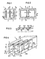
- Figures 1 and 2 show in two side views an embodiment of a converter according to the invention.
- the three lamellae made of piezoceramic are designated by 2.
- the individual lamellae 2 are at least 4 times larger (preferably 0.5 to 2.5 mm) apart from one another in comparison to their thickness (preferably 0.08 to 0.3 mm).
- With 3 is on the existing between the lamellae 2 filling spaces.
- bile material such as polyethylene.
- lines 31 is indicated in Figure 1 that this polyethylene 3 was originally a respective plate, which were assembled together with the slats 2 in a sandwich construction and then thermoplastic hot glued together.
- an adhesive connection is present in the finished transducer 1.
- a potting compound for example with silicone rubber
- the ceramic fins 2 are embedded in the material 3 on all sides, from the very beginning. Because of the thermoplastic behavior of the polyethylene, the lamellae 2 are embedded in the respective surface of a polyethylene plate 3.
- FIG. 2 The side view of Figure 2 shows two ceramic lamellae 2 and 21 which are arranged side by side.
- the second lamella 21 cannot be seen in FIG. 1, since it lies behind a respective lamella 2.
- the slats 2 and 21 shown are each a single, continuous slat.
- a sub as shown in Figure 2 Division leads in particular to the fact that in the direction of the mutually adjacent slats 2 and 21 (ie in the horizontal direction lying in the representation plane of FIG.
- an additional support is designated.
- Such an additional support can offer particular advantages if a foam is used as material 3.
- Such an additional support 5 gives a denser surface.
- this additional layer can even be advantageously implemented as an integral part of the foam material, i.e. the foam material is compacted on the surface in question.
- Such an additional support or superficial compression of the material 3 may even be necessary in order to achieve an increase in the mechanical resistance of the surface of the transducer 1, which is to be used as a sound radiation and / or reception surface in later operation.
- Arrows 6 indicate such sound radiation.
- sound radiation 16 from the corresponding surface of the transducer 1 can also be provided. If sound radiation (or sound reception) as indicated by 16 is to be provided, it is usually advisable not to provide a division into lamellae 2 and 21 as shown in FIG.
- FIG. 3 shows (compared to Figures 1 and 2) one Supervision, on an enlarged scale.
- This FIG. 3 serves primarily to show a special electrode arrangement, shown on a single lamella 2.
- 41 and 141 are, as can be seen, subdivided electrode assignments of one surface of the lamella 2.
- 42, 142 and 242 are corresponding subdivided electrode assignments of the opposite surface of the lamella 2.
- the electrode division in FIG. 3 serves to increase the electrical matching resistance or to achieve a higher electrical voltage, for example in reception mode.
- the sequence of the relative polarization orientations in the lamella is indicated at 50. As can be seen, the individual regions given by the electrode division shown are electrically connected in series.
- a converter according to the invention which has a plurality of such lamellae 2 (and possibly also lamellae 21)
- different interconnections can be provided for the transmission mode and for the reception mode. For example, it may be beneficial to connect all slats electrically in parallel for transmission (relatively low excitation voltage is required) and to connect all, or at least a certain number, slats 2 in series (results in high electrical receive voltage).
- Figure 4 shows an essentially merely schematic, perspective view of a converter according to the invention with lamellae 2 and the material filling the spaces.
- rial 3 Only indicated in Figure 4 is the possibility that slats (see Figure 2) are divided into individual slats 2, 21, 121 (to reduce cross coupling in direction b). That area of the
- Transducer 1 can be used for sound radiation and / or reception, which has a radiation direction indicated by 116.
- the polyethylene used as material 3, for example, which surrounds the slats 2 (and 21 and 121) can, as shown in FIG. 4, be largely transparent.
- 51 indicates a set of connecting lines which lead to the respective electrode assignment of the individual lamellae 2, 21, 121. The person skilled in the art can specify any other connection lines to be provided.
Landscapes
- Physics & Mathematics (AREA)
- Engineering & Computer Science (AREA)
- Acoustics & Sound (AREA)
- Multimedia (AREA)
- Transducers For Ultrasonic Waves (AREA)
Applications Claiming Priority (2)
| Application Number | Priority Date | Filing Date | Title |
|---|---|---|---|
| DE19843409789 DE3409789A1 (de) | 1984-03-16 | 1984-03-16 | Piezoelektrischer luft-ultraschallwandler mit breitbandcharakteristik |
| DE3409789 | 1984-03-16 |
Publications (3)
| Publication Number | Publication Date |
|---|---|
| EP0154706A2 true EP0154706A2 (fr) | 1985-09-18 |
| EP0154706A3 EP0154706A3 (en) | 1987-04-01 |
| EP0154706B1 EP0154706B1 (fr) | 1990-03-21 |
Family
ID=6230775
Family Applications (1)
| Application Number | Title | Priority Date | Filing Date |
|---|---|---|---|
| EP84115390A Expired - Lifetime EP0154706B1 (fr) | 1984-03-16 | 1984-12-13 | Transducteur air-ultrason piézoélectrique à caractéristique à large bande |
Country Status (4)
| Country | Link |
|---|---|
| US (1) | US4677337A (fr) |
| EP (1) | EP0154706B1 (fr) |
| JP (1) | JPS60236600A (fr) |
| DE (3) | DE3409789A1 (fr) |
Cited By (4)
| Publication number | Priority date | Publication date | Assignee | Title |
|---|---|---|---|---|
| EP0181506A3 (en) * | 1984-10-15 | 1987-03-25 | Edo Corporation/Western Division | Flexible piezoelectric transducer assembly |
| US4914565A (en) * | 1987-05-22 | 1990-04-03 | Siemens Aktiengesellschaft | Piezo-electric transducer having electrodes that adhere well both to ceramic as well as to plastics |
| WO1991000153A1 (fr) * | 1989-06-23 | 1991-01-10 | Siemens Aktiengesellschaft | Transducteur d'ultrasons a large bande |
| EP0451306A1 (fr) * | 1990-04-09 | 1991-10-16 | Siemens Aktiengesellschaft | Transducteur strafifié d'ultrason à sélectivité de fréquence |
Families Citing this family (21)
| Publication number | Priority date | Publication date | Assignee | Title |
|---|---|---|---|---|
| US5488952A (en) * | 1982-02-24 | 1996-02-06 | Schoolman Scientific Corp. | Stereoscopically display three dimensional ultrasound imaging |
| US4864179A (en) * | 1986-10-10 | 1989-09-05 | Edo Corporation, Western Division | Two-dimensional piezoelectric transducer assembly |
| US4833360A (en) * | 1987-05-15 | 1989-05-23 | Board Of Regents The University Of Texas System | Sonar system using acoustically transparent continuous aperture transducers for multiple beam beamformation |
| US4985926A (en) * | 1988-02-29 | 1991-01-15 | Motorola, Inc. | High impedance piezoelectric transducer |
| US5852589A (en) * | 1990-07-19 | 1998-12-22 | Raytheon Company | Low cost composite transducer |
| GB9224292D0 (en) * | 1992-11-19 | 1993-02-17 | Flow Research Evaluation Diagn | Sonar transducers |
| US6225728B1 (en) * | 1994-08-18 | 2001-05-01 | Agilent Technologies, Inc. | Composite piezoelectric transducer arrays with improved acoustical and electrical impedance |
| US20030036746A1 (en) | 2001-08-16 | 2003-02-20 | Avi Penner | Devices for intrabody delivery of molecules and systems and methods utilizing same |
| US6255761B1 (en) * | 1999-10-04 | 2001-07-03 | The United States Of America As Represented By The Secretary Of The Navy | Shaped piezoelectric composite transducer |
| JP3449345B2 (ja) * | 2000-08-11 | 2003-09-22 | 株式会社村田製作所 | センサアレイおよび送受信装置 |
| US7489967B2 (en) * | 2004-07-09 | 2009-02-10 | Cardiac Pacemakers, Inc. | Method and apparatus of acoustic communication for implantable medical device |
| JP5121011B2 (ja) * | 2004-11-24 | 2013-01-16 | レモン メディカル テクノロジーズ リミテッド | 音響トランスデューサを組み込んだインプラント可能な医療機器 |
| US7522962B1 (en) | 2004-12-03 | 2009-04-21 | Remon Medical Technologies, Ltd | Implantable medical device with integrated acoustic transducer |
| US7615012B2 (en) * | 2005-08-26 | 2009-11-10 | Cardiac Pacemakers, Inc. | Broadband acoustic sensor for an implantable medical device |
| US7570998B2 (en) * | 2005-08-26 | 2009-08-04 | Cardiac Pacemakers, Inc. | Acoustic communication transducer in implantable medical device header |
| US7912548B2 (en) * | 2006-07-21 | 2011-03-22 | Cardiac Pacemakers, Inc. | Resonant structures for implantable devices |
| JP2009544366A (ja) * | 2006-07-21 | 2009-12-17 | カーディアック ペースメイカーズ, インコーポレイテッド | 金属製キャビティが植え込まれた医療器具に用いる超音波トランスデューサ |
| US8825161B1 (en) | 2007-05-17 | 2014-09-02 | Cardiac Pacemakers, Inc. | Acoustic transducer for an implantable medical device |
| EP2162185B1 (fr) * | 2007-06-14 | 2015-07-01 | Cardiac Pacemakers, Inc. | Système de recharge acoustique à plusieurs éléments |
| GB0813014D0 (en) | 2008-07-16 | 2008-08-20 | Groveley Detection Ltd | Detector and methods of detecting |
| JP7474187B2 (ja) * | 2020-12-15 | 2024-04-24 | 株式会社豊田中央研究所 | 吸音構造体 |
Family Cites Families (19)
| Publication number | Priority date | Publication date | Assignee | Title |
|---|---|---|---|---|
| US2408028A (en) * | 1934-01-19 | 1946-09-24 | Submarine Signal Co | Means for sending and receiving compressional waves |
| US2829361A (en) * | 1945-10-01 | 1958-04-01 | Gen Electric | Electroacoustic transducer |
| US2943297A (en) * | 1950-04-27 | 1960-06-28 | Raymond L Steinberger | Multiple element electroacoustic transducer |
| US3409869A (en) * | 1965-07-21 | 1968-11-05 | Navy Usa | Deep submergence acoustic transducer array construction |
| US3353150A (en) * | 1965-10-22 | 1967-11-14 | Atlantic Res Corp | Foam-filled transducer |
| US3907062A (en) * | 1973-12-17 | 1975-09-23 | Us Navy | Compliant blanket acoustic baffle |
| US3924259A (en) * | 1974-05-15 | 1975-12-02 | Raytheon Co | Array of multicellular transducers |
| US4122725A (en) * | 1976-06-16 | 1978-10-31 | The United States Of America As Represented By The Administrator Of The National Aeronautics And Space Administration | Length mode piezoelectric ultrasonic transducer for inspection of solid objects |
| JPS5339771A (en) * | 1976-09-24 | 1978-04-11 | Nec Corp | Water pressure resisting transmitter and receelver |
| JPS5353393A (en) * | 1976-10-25 | 1978-05-15 | Matsushita Electric Ind Co Ltd | Ultrasonic probe |
| US4376302A (en) * | 1978-04-13 | 1983-03-08 | The United States Of America As Represented By The Secretary Of The Navy | Piezoelectric polymer hydrophone |
| DE2829539C2 (de) * | 1978-07-05 | 1980-01-17 | Siemens Ag, 1000 Berlin Und 8000 Muenchen | Verfahren zur Herstellung von Ultraschallköpfen |
| DE2842086B2 (de) * | 1978-09-27 | 1980-10-09 | Siemens Ag, 1000 Berlin Und 8000 Muenchen | Elektroakustischer Wandler mit hohem Wirkungsgrad |
| US4233477A (en) * | 1979-01-31 | 1980-11-11 | The United States Of America As Represented By The Secretary Of The Navy | Flexible, shapeable, composite acoustic transducer |
| JPS56161799A (en) * | 1980-05-15 | 1981-12-12 | Matsushita Electric Ind Co Ltd | Ultrasonic wave probe |
| US4366406A (en) * | 1981-03-30 | 1982-12-28 | General Electric Company | Ultrasonic transducer for single frequency applications |
| US4518889A (en) * | 1982-09-22 | 1985-05-21 | North American Philips Corporation | Piezoelectric apodized ultrasound transducers |
| US4550606A (en) * | 1982-09-28 | 1985-11-05 | Cornell Research Foundation, Inc. | Ultrasonic transducer array with controlled excitation pattern |
| US4514247A (en) * | 1983-08-15 | 1985-04-30 | North American Philips Corporation | Method for fabricating composite transducers |
-
1984
- 1984-03-16 DE DE19843409789 patent/DE3409789A1/de not_active Withdrawn
- 1984-03-16 DE DE8408180U patent/DE8408180U1/de not_active Expired
- 1984-12-13 DE DE8484115390T patent/DE3481741D1/de not_active Expired - Lifetime
- 1984-12-13 EP EP84115390A patent/EP0154706B1/fr not_active Expired - Lifetime
-
1985
- 1985-03-14 JP JP60051561A patent/JPS60236600A/ja active Granted
-
1986
- 1986-10-29 US US06/926,801 patent/US4677337A/en not_active Expired - Fee Related
Cited By (7)
| Publication number | Priority date | Publication date | Assignee | Title |
|---|---|---|---|---|
| EP0181506A3 (en) * | 1984-10-15 | 1987-03-25 | Edo Corporation/Western Division | Flexible piezoelectric transducer assembly |
| US4914565A (en) * | 1987-05-22 | 1990-04-03 | Siemens Aktiengesellschaft | Piezo-electric transducer having electrodes that adhere well both to ceramic as well as to plastics |
| EP0292014A3 (fr) * | 1987-05-22 | 1990-04-25 | Siemens Aktiengesellschaft | Transducteur piézo-électrique à électrodes adhérant bien aux matériaux céramiques et synthétiques |
| WO1991000153A1 (fr) * | 1989-06-23 | 1991-01-10 | Siemens Aktiengesellschaft | Transducteur d'ultrasons a large bande |
| US5254900A (en) * | 1989-06-23 | 1993-10-19 | Siemens Aktiengesellschaft | Broad beam ultrasonic transducer |
| EP0451306A1 (fr) * | 1990-04-09 | 1991-10-16 | Siemens Aktiengesellschaft | Transducteur strafifié d'ultrason à sélectivité de fréquence |
| US5457353A (en) * | 1990-04-09 | 1995-10-10 | Siemens Aktiengesellschaft | Frequency-selective ultrasonic sandwich transducer |
Also Published As
| Publication number | Publication date |
|---|---|
| EP0154706B1 (fr) | 1990-03-21 |
| US4677337A (en) | 1987-06-30 |
| JPS60236600A (ja) | 1985-11-25 |
| EP0154706A3 (en) | 1987-04-01 |
| JPH0458760B2 (fr) | 1992-09-18 |
| DE8408180U1 (de) | 1986-07-17 |
| DE3481741D1 (de) | 1990-04-26 |
| DE3409789A1 (de) | 1985-09-26 |
Similar Documents
| Publication | Publication Date | Title |
|---|---|---|
| EP0154706B1 (fr) | Transducteur air-ultrason piézoélectrique à caractéristique à large bande | |
| DE69516055T2 (de) | Ultraschallumwandler | |
| EP0531761B1 (fr) | Absorbeur | |
| DE60032535T2 (de) | Resonator mit akustischen Volumenwellen mit verbesserter lateralen Modeunterdrückung | |
| DE1132593B (de) | Akustisch wirksame Platte, insbesondere zur Ankopplung an einen elektroakustischen Wandler | |
| DE10042185B4 (de) | Piezoelektrischer elektroakustischer Wandler | |
| DE2021656C3 (fr) | ||
| DE3119272A1 (de) | "bogenabtastungs-ultraschallwandler-anordnung" | |
| EP0041664A1 (fr) | Procédé de fabrication d'un agencement d'un transducteur ultrasonique | |
| DE3526488A1 (de) | Ultraschall-wandler mit piezoelektrischem verbundmaterial | |
| EP0178346A1 (fr) | Transducteur à ultrasons | |
| WO1984002998A1 (fr) | Absorption acoustique par produit alveolaire | |
| DE2946392A1 (de) | Schallisolierendes gebaeude- oder konstruktionselement | |
| DE60310451T2 (de) | Doppelwandiges akustisches paneel | |
| EP0924959B1 (fr) | Arrangement de reproduction sonore | |
| DE2150194B2 (de) | Elektrostatischer Lautsprecher | |
| DE3005708C2 (de) | Wandlerplatte für piezoelektrische Wandler | |
| DE3443869C2 (fr) | ||
| US4348904A (en) | Acoustic impedance matching device | |
| DE2351665B2 (de) | Rechtwinklige AT-geschnittene Quarzkristallplatte | |
| EP1078551B1 (fr) | Haut-parleur a panneaux | |
| DE69629307T2 (de) | Verfahren zur dämpfung von schwingungen und der von einem material abgestrahlten druckwelle | |
| EP0189520A1 (fr) | Procédé de fabrication d'un système d'antennes à ultrasons | |
| DE9408118U1 (de) | Schallabsorber | |
| WO2023227732A1 (fr) | Dispositif de protection acoustique comprenant des métamatériaux vibroacoustiques et mur antibruit comprenant au moins un dispositif de protection acoustique de ce type |
Legal Events
| Date | Code | Title | Description |
|---|---|---|---|
| PUAI | Public reference made under article 153(3) epc to a published international application that has entered the european phase |
Free format text: ORIGINAL CODE: 0009012 |
|
| 17P | Request for examination filed |
Effective date: 19841221 |
|
| AK | Designated contracting states |
Designated state(s): CH DE FR GB IT LI SE |
|
| PUAL | Search report despatched |
Free format text: ORIGINAL CODE: 0009013 |
|
| AK | Designated contracting states |
Kind code of ref document: A3 Designated state(s): CH DE FR GB IT LI SE |
|
| 17Q | First examination report despatched |
Effective date: 19881121 |
|
| GRAA | (expected) grant |
Free format text: ORIGINAL CODE: 0009210 |
|
| AK | Designated contracting states |
Kind code of ref document: B1 Designated state(s): CH DE FR GB IT LI SE |
|
| REF | Corresponds to: |
Ref document number: 3481741 Country of ref document: DE Date of ref document: 19900426 |
|
| ET | Fr: translation filed | ||
| ITF | It: translation for a ep patent filed | ||
| GBT | Gb: translation of ep patent filed (gb section 77(6)(a)/1977) | ||
| ITTA | It: last paid annual fee | ||
| PLBE | No opposition filed within time limit |
Free format text: ORIGINAL CODE: 0009261 |
|
| STAA | Information on the status of an ep patent application or granted ep patent |
Free format text: STATUS: NO OPPOSITION FILED WITHIN TIME LIMIT |
|
| 26N | No opposition filed | ||
| EAL | Se: european patent in force in sweden |
Ref document number: 84115390.1 |
|
| PGFP | Annual fee paid to national office [announced via postgrant information from national office to epo] |
Ref country code: SE Payment date: 19951221 Year of fee payment: 12 |
|
| PG25 | Lapsed in a contracting state [announced via postgrant information from national office to epo] |
Ref country code: SE Effective date: 19961214 |
|
| EUG | Se: european patent has lapsed |
Ref document number: 84115390.1 |
|
| PGFP | Annual fee paid to national office [announced via postgrant information from national office to epo] |
Ref country code: GB Payment date: 19971113 Year of fee payment: 14 |
|
| PGFP | Annual fee paid to national office [announced via postgrant information from national office to epo] |
Ref country code: FR Payment date: 19971219 Year of fee payment: 14 |
|
| PGFP | Annual fee paid to national office [announced via postgrant information from national office to epo] |
Ref country code: CH Payment date: 19980316 Year of fee payment: 14 |
|
| PG25 | Lapsed in a contracting state [announced via postgrant information from national office to epo] |
Ref country code: GB Free format text: LAPSE BECAUSE OF NON-PAYMENT OF DUE FEES Effective date: 19981213 |
|
| PG25 | Lapsed in a contracting state [announced via postgrant information from national office to epo] |
Ref country code: LI Free format text: LAPSE BECAUSE OF NON-PAYMENT OF DUE FEES Effective date: 19981231 Ref country code: CH Free format text: LAPSE BECAUSE OF NON-PAYMENT OF DUE FEES Effective date: 19981231 |
|
| PGFP | Annual fee paid to national office [announced via postgrant information from national office to epo] |
Ref country code: DE Payment date: 19990219 Year of fee payment: 15 |
|
| GBPC | Gb: european patent ceased through non-payment of renewal fee |
Effective date: 19981213 |
|
| REG | Reference to a national code |
Ref country code: CH Ref legal event code: PL |
|
| PG25 | Lapsed in a contracting state [announced via postgrant information from national office to epo] |
Ref country code: FR Free format text: LAPSE BECAUSE OF NON-PAYMENT OF DUE FEES Effective date: 19990831 |
|
| REG | Reference to a national code |
Ref country code: FR Ref legal event code: ST |
|
| PG25 | Lapsed in a contracting state [announced via postgrant information from national office to epo] |
Ref country code: DE Free format text: LAPSE BECAUSE OF NON-PAYMENT OF DUE FEES Effective date: 20001003 |