EP0178346A1 - Transducteur à ultrasons - Google Patents
Transducteur à ultrasons Download PDFInfo
- Publication number
- EP0178346A1 EP0178346A1 EP84112594A EP84112594A EP0178346A1 EP 0178346 A1 EP0178346 A1 EP 0178346A1 EP 84112594 A EP84112594 A EP 84112594A EP 84112594 A EP84112594 A EP 84112594A EP 0178346 A1 EP0178346 A1 EP 0178346A1
- Authority
- EP
- European Patent Office
- Prior art keywords
- top plate
- side plate
- ultrasonic transducer
- cylindrical side
- plate
- Prior art date
- Legal status (The legal status is an assumption and is not a legal conclusion. Google has not performed a legal analysis and makes no representation as to the accuracy of the status listed.)
- Granted
Links
Images

Classifications
-
- B—PERFORMING OPERATIONS; TRANSPORTING
- B06—GENERATING OR TRANSMITTING MECHANICAL VIBRATIONS IN GENERAL
- B06B—METHODS OR APPARATUS FOR GENERATING OR TRANSMITTING MECHANICAL VIBRATIONS OF INFRASONIC, SONIC, OR ULTRASONIC FREQUENCY, e.g. FOR PERFORMING MECHANICAL WORK IN GENERAL
- B06B1/00—Methods or apparatus for generating mechanical vibrations of infrasonic, sonic, or ultrasonic frequency
- B06B1/02—Methods or apparatus for generating mechanical vibrations of infrasonic, sonic, or ultrasonic frequency making use of electrical energy
- B06B1/06—Methods or apparatus for generating mechanical vibrations of infrasonic, sonic, or ultrasonic frequency making use of electrical energy operating with piezoelectric effect or with electrostriction
- B06B1/0644—Methods or apparatus for generating mechanical vibrations of infrasonic, sonic, or ultrasonic frequency making use of electrical energy operating with piezoelectric effect or with electrostriction using a single piezoelectric element
- B06B1/0662—Methods or apparatus for generating mechanical vibrations of infrasonic, sonic, or ultrasonic frequency making use of electrical energy operating with piezoelectric effect or with electrostriction using a single piezoelectric element with an electrode on the sensitive surface
- B06B1/067—Methods or apparatus for generating mechanical vibrations of infrasonic, sonic, or ultrasonic frequency making use of electrical energy operating with piezoelectric effect or with electrostriction using a single piezoelectric element with an electrode on the sensitive surface which is used as, or combined with, an impedance matching layer
-
- G—PHYSICS
- G10—MUSICAL INSTRUMENTS; ACOUSTICS
- G10K—SOUND-PRODUCING DEVICES; METHODS OR DEVICES FOR PROTECTING AGAINST, OR FOR DAMPING, NOISE OR OTHER ACOUSTIC WAVES IN GENERAL; ACOUSTICS NOT OTHERWISE PROVIDED FOR
- G10K11/00—Methods or devices for transmitting, conducting or directing sound in general; Methods or devices for protecting against, or for damping, noise or other acoustic waves in general
- G10K11/002—Devices for damping, suppressing, obstructing or conducting sound in acoustic devices
-
- G—PHYSICS
- G10—MUSICAL INSTRUMENTS; ACOUSTICS
- G10K—SOUND-PRODUCING DEVICES; METHODS OR DEVICES FOR PROTECTING AGAINST, OR FOR DAMPING, NOISE OR OTHER ACOUSTIC WAVES IN GENERAL; ACOUSTICS NOT OTHERWISE PROVIDED FOR
- G10K11/00—Methods or devices for transmitting, conducting or directing sound in general; Methods or devices for protecting against, or for damping, noise or other acoustic waves in general
- G10K11/02—Mechanical acoustic impedances; Impedance matching, e.g. by horns; Acoustic resonators
-
- H—ELECTRICITY
- H01—ELECTRIC ELEMENTS
- H01J—ELECTRIC DISCHARGE TUBES OR DISCHARGE LAMPS
- H01J61/00—Gas-discharge or vapour-discharge lamps
- H01J61/02—Details
- H01J61/30—Vessels; Containers
- H01J61/32—Special longitudinal shape, e.g. for advertising purposes
- H01J61/327—"Compact"-lamps, i.e. lamps having a folded discharge path
Definitions
- This invention relates to an ultrasonic transducer capable of transmitting and / or receiving ultrasonic waves.
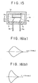
- FIG. 15 Such a transducer is shown in Fig. 15, in which reference numeral 1 designates a swing case which is formed of metal such as stainless steel and is composed of a cylindrical side plate 1b and an upper plate 1a which is so at one end of the side plate 1b it is intended to complete them.
- 2 designates a piezoelectric ceramic disk which is connected to the inner wall of the top plate 1a for the purpose of a common vibration, thereby producing an integrated connection.
- the ceramic disc 2 is provided on its opposite sides with a pair of electrodes 2a and 2b.
- the open end section of the oscillating housing 1 is closed by a cover plate 3.
- a pair of end terminal pins 4a and 4b are provided, one end of which is lead wire 5a and 5b are connected to the electrodes 2a and 2b.
- 6 denotes an insulating layer, which is formed, for example, from an epoxy resin in order to seal the oscillating housing 1.
- the piezoelectric ceramic disk 2 When an electric field is applied to the pins 4a and 4b to apply an AC voltage between the opposing electrodes 2a and 2b, the piezoelectric ceramic disk 2 is excited to longitudinal or bending vibrations so that an ultrasonic wave is generated from the top plate 1a in which the integrated ceramic disc 2 is integrated. On the other hand, when the top plate 1a receives an ultrasonic wave, the piezoelectric ceramic disk 2 deforms such that an output with an intensity corresponding to the incident ultrasonic wave is output from the electrodes 2a and 2b.
- the ultrasonic transducer of the type mentioned above has proven to be poorly suited for use as a proximity switch or sensor for the removal of a substance. Since the vibrating housing is formed from metal, the wave-transmitting and receiving section, which is formed from the top plate 1a and the piezoelectric ceramic disk 2, has such a high mechanical quality factor Q that, as shown in FIG. 16a, the transducer exhibits pulse characteristics, which have a long pulse decay time. It is therefore possible that when the transducer receives an ultrasound wave that has been reflected from the nearest substance during the transmission of the ultrasound wave, it is unable to function as a sensor or detector.
- the resulting transducer has superior wave transmission and reception properties, in particular an improved response behavior, compared to that transducer whose oscillating housing is made of a non-porous plastic.
- an ultrasonic transducer having a vibrating housing member having a cylindrical side plate and a shaft transmitting and receiving top plate provided at one end of the side plate, a piezoelectric element which is integrally formed with the inner wall of the Top plate is connected, and electrodes, which are arranged on the piezoelectric element, so that ultrasonic waves can be generated from the top plate when an electric field is applied to the electrodes, and / or an electrical output from the electrodes is given when the top plate Receives ultrasonic waves, wherein the top plate is made of a porous plastic.
- FIGS. 1 and 2 form an embodiment of the ultrasonic transducer according to the invention.
- those components which correspond to those in FIG. 15 are designated with the same reference numerals, to which, however, 10 has been added.
- the exemplary embodiment shown in FIGS. 1 and 2 differs from the conventional converter shown in FIG. 15 in that the oscillating housing 11 of FIGS. 1 and 2 is formed from a porous plastic.
- a piezoelectric element 12 with electrodes 12a and 12b is bonded to the inner surface of an upper plate 11a of the housing part 11 to form an integrated component.
- the housing part 11 has a cylindrical side plate 11b which is integrally connected to the top plate 11a.
- the open end portion of the housing part 11 is provided with a cover plate 13 to which a pair of terminal pins 14a and 14b are attached.
- Lead wires 15a and 15b extend between electrode 12a and pin 14a and between electrode 12b and pin 14b, respectively.
- the cover plate 13 is covered with an insulating layer 16.
- Denoted at 17 is an insulator which is provided when the cover plate is formed from an electrical conductor in order to provide the insulation between the two connection pins 14a and 14b.
- both the top plate 11a and the side plate 11b are formed from porous plastic.
- porous plastic as used herein is intended to include a synthetic polymeric material that has a large number of closed cells distributed within the polymeric material.
- suitable porous plastics are synthetic polymer materials in which a large number of glass microballoons are distributed, and foamed synthetic polymer materials materials which are produced using foaming agents in a conventional manner.
- the porous plastic preferably has an average pore diameter which is between 50 and 100 ⁇ .
- suitable polymer materials are epoxy resins, polyolefin resins, styrene resins, acrylic resins and vinyl chloride resins.
- the vibrating case 11 of the present invention is molded from porous plastic, so that the Q m of the wave transmitting and receiving portion of the ultrasonic transducer of this invention is low, so that the pulse rise and fall times can be shortened as shown in Fig. 16b is.
- the reduction in the pulse decay time advantageously leads to a reduction in the reverberation time.
- the top plate 11a contains a relatively large amount of air, the acoustic impedance of the top plate 11a approaches that of air. Therefore, the fitting conditions between the top plate 11a and the ambient air are improved, which leads to an improvement in response, that is, a more intense output can be obtained after receiving an ultrasonic wave of constant intensity.
- the conventional ultrasonic transducer whose housing is made of stainless steel, a pulse rise time of 0.5 ms, a pulse fall time of 2.0 ms and an output voltage of 0.4 V.
- An ultrasonic transducer, the oscillating housing of which is made of non-porous epoxy resin provides a pulse rise time of 0.2 mA, a pulse fall time of 1.2 ms and an output voltage of 2.6 V.
- the oscillating body is formed of an epoxy resin, in which a large Distributed number of glass microballoons that have a diameter of 50 to 100 microns, there is a pulse rise and fall time of 0.2 or 1.2 ms, and the output voltage is 6.4 V.
- the thickness of the top plate 11 a of the vibrating housing 11 is about 1/4 of the wavelength of the speed of sound of the top plate 11 a, for the reason of achieving the best response.
- both the top plate 11a and the cylindrical side plate 11b are molded from solid plastic. A similar improvement can be obtained even if the top plate is molded from a porous plastic alone.
- a cylindrical side plate 11b is integrally provided at one end with a top plate 11a molded from porous plastic of the type just mentioned.
- the other designs of the transducer are substantially the same as in the embodiment of Figs. 1 and 2, and their detailed explanation is omitted here.
- 4 and 5 depict exemplary embodiments similar to that of FIG. 3.
- the outer periphery of the top plate 11a is in contact with the inner surface of the cylindrical side plate 11b.
- the end portion of the top plate 11a and the side plate 11b are cut together diagonally for abutment engagement.
- the top plate 11a can be attached to the side plate 11b by any known means, such as glue.
- the cylindrical side plate 11b is preferably molded from a material whose acoustic impedance is greater than that of the top plate 11a, for the purpose of achieving a reduction in reverberation time.
- a suitable material for the side plate 11b are plastics, metals and ceramic materials. If both the top plate and the side plate of the vibrating housing are molded from a porous plastic, then the vibration on the side of the vibrating housing 11 is not completely damped, and the reverberation time cannot be reduced below a certain limit.
- the vibration of the top plate 11a at the interface between the top plate 11a and the side plate 11b reflects and distributes and is prevented from proceeding to the side plate 11b.
- the reverberation time becomes shorter compared to the transducer in which the vibrating housing is completely molded from porous plastic.
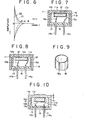
- the ultrasonic transducer whose oscillating housing is formed from porous plastic with an acoustic impedance of 1 x 3000 g / cm z s, shows a wave-transmitting pulse characteristic as shown by line 20 in FIG. 6.
- the vibrating housing is formed from a cylindrical side plate, which is formed from stainless steel with an acoustic impedance of 7.8 x 5000 g / cm 2 s, and an upper plate, which is made of a porous plastic with 1 x 3000 g / cm z s is shaped on acoustic impedance, then the transducer provides the pulse characteristic as shown by the broken line 21 in FIG. 6. This means that the reverberation time can be reduced to less than 1.0 ms.
- Such a reduction in reverberation time can also be accomplished by providing an integrated tubular part or parts on the outer and / or inner circumference of the cylindrical side plate of the transducer shown in Figs. 1 and 2, wherein the tubular part has a higher acoustic impedance than the cylindrical side plate.
- a tubular member 18 is provided within a swing housing and bonded to the inner periphery of its cylindrical side plate 11b.
- the tubular member 18 is adhered to the outer periphery of the side plate 11b.
- tubular member 18 improves wire eieschwingungsdämpfende effect on the side of the oscillating body, in order to reduce the reverberation time.
- Attachment of tubular member 18 to side plate 11b can be accomplished by any known means, such as glue.
- the tubular part 1 is provided within the housing 11, then it is expedient to design the tubular part as an elastic tube, generally a metal tube which has a slot 18a which extends parallel to the axis of the tube.
- the tube 18 has a larger outer diameter than the inner diameter of the side plate 11b in the free state.
- the tubular member 18 is provided outside the housing 11, it is possible to use an elastic tube, such as a rubber tube, which has a smaller inner diameter than the outer diameter of the cylindrical side plate 11b. By fitting the rubber tube 18 around the circumference of the side plate 11b, the tube is held in pressure contact with the side plate 11b.
- the elastic tubular member it is not necessary for the tubular member to be made of a material having a greater acoustic impedance than the side plate 11b because of the fact that the side plate 11b is always the same. Forces in the direction perpendicular to the axis of the cylindrical. The side plate 11b is exposed and is prevented from vibrating.
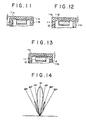
- the thickness of the top plate 11a is suddenly changed at a ring portion near the outer periphery of the piezoelectric disk 12 by the transverse vibration that is circumferential be wedge-shaped).
- the height of the raised portion 11c and the depth of the annular groove 11d are not larger than 1/3 of the thickness D of the top plate 11a to prevent a decrease in responsiveness.
Landscapes
- Engineering & Computer Science (AREA)
- Physics & Mathematics (AREA)
- Acoustics & Sound (AREA)
- Multimedia (AREA)
- Mechanical Engineering (AREA)
- Transducers For Ultrasonic Waves (AREA)
Priority Applications (1)
| Application Number | Priority Date | Filing Date | Title |
|---|---|---|---|
| DE8484112594T DE3486035D1 (de) | 1984-10-18 | 1984-10-18 | Ultraschallwandler. |
Applications Claiming Priority (3)
| Application Number | Priority Date | Filing Date | Title |
|---|---|---|---|
| JP2434684U JPS60136599U (ja) | 1984-02-21 | 1984-02-21 | 超音波セラミツクセンサ |
| JP2648784U JPS60139399U (ja) | 1984-02-24 | 1984-02-24 | 超音波セラミツクセンサ |
| JP5034784U JPS60163899U (ja) | 1984-04-06 | 1984-04-06 | 超音波セラミツクセンサ |
Publications (2)
| Publication Number | Publication Date |
|---|---|
| EP0178346A1 true EP0178346A1 (fr) | 1986-04-23 |
| EP0178346B1 EP0178346B1 (fr) | 1993-01-13 |
Family
ID=27284612
Family Applications (1)
| Application Number | Title | Priority Date | Filing Date |
|---|---|---|---|
| EP84112594A Expired - Lifetime EP0178346B1 (fr) | 1984-02-21 | 1984-10-18 | Transducteur à ultrasons |
Country Status (5)
| Country | Link |
|---|---|
| US (1) | US4556814A (fr) |
| EP (1) | EP0178346B1 (fr) |
| DE (1) | DE3505872C2 (fr) |
| DK (1) | DK168317B1 (fr) |
| FR (1) | FR2559985B1 (fr) |
Cited By (9)
| Publication number | Priority date | Publication date | Assignee | Title |
|---|---|---|---|---|
| US4914959A (en) * | 1987-04-24 | 1990-04-10 | Den Norske Stats Oljeselskap A.S. | Ultrasonic flow meter using obliquely directed transducers |
| US4945276A (en) * | 1987-04-24 | 1990-07-31 | Den Norske Stats Oljeselskap A.S. | Transducer for arranging in a fluid, particularly for the measurement of the flow-velocity of a fluid in a pipe, by transmitting/receiving sonic pulses |
| EP0361757A3 (fr) * | 1988-09-29 | 1991-09-25 | British Gas plc | Dispositif d'adaptation |
| WO1995007529A1 (fr) * | 1993-09-10 | 1995-03-16 | Siemens Aktiengesellschaft | Transducteur ultrasonore a adaptateur |
| DE19512417A1 (de) * | 1995-04-03 | 1996-10-10 | Marco Systemanalyse Entw | Piezoelektrischer Ultraschallwandler |
| WO1997026646A1 (fr) * | 1996-01-18 | 1997-07-24 | Itt Automotive Europe Gmbh | Transducteur ultrasonique pourvu d'un corps d'amortissement |
| WO1998004361A1 (fr) * | 1996-07-26 | 1998-02-05 | Siemens Aktiengesellschaft | Transducteur ultrasonique a element d'adaptation quart d'onde en forme de disque |
| RU2285355C2 (ru) * | 2004-03-05 | 2006-10-10 | Санкт-Петербургский государственный университет | Ультразвуковой пьезопреобразователь с сухим акустическим контактом |
| WO2017005686A1 (fr) * | 2015-07-07 | 2017-01-12 | Valeo Schalter Und Sensoren Gmbh | Capteur à ultrasons pour un véhicule automobile, véhicule automobile ainsi que procédé de fabrication d'un capteur à ultrasons |
Families Citing this family (52)
| Publication number | Priority date | Publication date | Assignee | Title |
|---|---|---|---|---|
| DE3545381C2 (de) * | 1985-12-20 | 1994-02-24 | Siemens Ag | Ultraschallwandler zur Messung der Schalleistung eines fokussierten Ultraschallfeldes |
| JPH0749914Y2 (ja) * | 1986-01-29 | 1995-11-13 | 株式会社村田製作所 | 超音波トランスデユ−サ |
| US4770038A (en) * | 1986-02-13 | 1988-09-13 | The United States Of America As Represented By The Administrator Of National Aeronautics And Space Administration | Ultrasonic depth gauge for liquids under high pressure |
| JPH057835Y2 (fr) * | 1986-06-10 | 1993-02-26 | ||
| US4783997A (en) * | 1987-02-26 | 1988-11-15 | Panametrics, Inc. | Ultrasonic transducers for high temperature applications |
| DE8805953U1 (de) * | 1988-05-05 | 1988-07-07 | Höntzsch GmbH, 71334 Waiblingen | Elektroakustischer Wandler |
| DE4120681A1 (de) * | 1990-08-04 | 1992-02-06 | Bosch Gmbh Robert | Ultraschallwandler |
| DE4028315A1 (de) * | 1990-09-06 | 1992-03-12 | Siemens Ag | Ultraschallwandler fuer die laufzeitmessung von ultraschall-impulsen in einem gas |
| US5121628A (en) * | 1990-10-09 | 1992-06-16 | Merkl Arthur W | Ultrasonic detection system |
| US5285789A (en) * | 1992-04-21 | 1994-02-15 | Hewlett-Packard Company | Ultrasonic transducer apodization using acoustic blocking layer |
| DE29611678U1 (de) * | 1996-07-04 | 1997-08-07 | Siemens AG, 80333 München | Schallwandler, insbesondere Ultraschallwandler |
| JPH10294995A (ja) * | 1997-04-21 | 1998-11-04 | Matsushita Electric Ind Co Ltd | 防滴型超音波送信器 |
| JP3596364B2 (ja) * | 1999-08-05 | 2004-12-02 | 松下電器産業株式会社 | 超音波送受波器および超音波流れ計測装置 |
| JP3501100B2 (ja) * | 2000-05-15 | 2004-02-23 | 株式会社村田製作所 | 超音波送受波器 |
| JP3768789B2 (ja) * | 2000-09-07 | 2006-04-19 | アルプス電気株式会社 | 超音波振動子及びウエット処理用ノズル並びにウエット処理装置 |
| DE10156259A1 (de) | 2001-11-09 | 2003-05-22 | Valeo Schalter & Sensoren Gmbh | Ultraschallsensor und Verfahren zur Herstellung eines Ultraschallsensors |
| JP3944052B2 (ja) * | 2001-12-27 | 2007-07-11 | 株式会社デンソー | 超音波送受波器及びこれを用いた超音波クリアランスソナー |
| JP3633926B2 (ja) * | 2002-01-28 | 2005-03-30 | 松下電器産業株式会社 | 超音波送受信器および超音波流量計 |
| JP4007128B2 (ja) * | 2002-03-22 | 2007-11-14 | 株式会社豊田中央研究所 | 圧力センサ及びセンサユニット |
| US6788620B2 (en) * | 2002-05-15 | 2004-09-07 | Matsushita Electric Industrial Co Ltd | Acoustic matching member, ultrasound transducer, ultrasonic flowmeter and method for manufacturing the same |
| JP4048886B2 (ja) * | 2002-09-10 | 2008-02-20 | 株式会社村田製作所 | 超音波センサ |
| WO2004025832A1 (fr) * | 2002-09-12 | 2004-03-25 | Philips Intellectual Property & Standards Gmbh | Resonateur a ondes acoustiques de masse equipe de moyens de suppression des ondulations passe-bande dans des filtres a ondes acoustiques de masse |
| US7075215B2 (en) * | 2003-07-03 | 2006-07-11 | Pathfinder Energy Services, Inc. | Matching layer assembly for a downhole acoustic sensor |
| US7513147B2 (en) | 2003-07-03 | 2009-04-07 | Pathfinder Energy Services, Inc. | Piezocomposite transducer for a downhole measurement tool |
| JP4503347B2 (ja) * | 2004-04-28 | 2010-07-14 | 日本電波工業株式会社 | 超音波探触子の製造方法 |
| DE102005001899B4 (de) * | 2005-01-14 | 2007-03-08 | Landis+Gyr Gmbh | Ultraschallkopf |
| JP2006203563A (ja) * | 2005-01-20 | 2006-08-03 | Nippon Soken Inc | 超音波センサ |
| US20060291677A1 (en) * | 2005-06-09 | 2006-12-28 | Airdigit Incorporation | High-fidelity piezoelectric contact-type microphone structure |
| CN101243558B (zh) * | 2005-08-12 | 2010-12-08 | 丹尼尔度量和控制公司 | 用于超声流量计的换能器壳体 |
| US7307373B2 (en) * | 2005-08-12 | 2007-12-11 | Daniel Measurement And Control, Inc. | Transducer assembly for an ultrasonic fluid meter |
| RU2450247C2 (ru) * | 2005-08-12 | 2012-05-10 | Дэниел Мэжэмэнт энд Кэнтроул, Инк. | Ультразвуковой расходомер, блок преобразователя для него и способ замены блока преобразователя |
| JP4407767B2 (ja) * | 2006-02-14 | 2010-02-03 | 株式会社村田製作所 | 超音波センサおよびその製造方法 |
| DE102006028211A1 (de) * | 2006-06-14 | 2007-12-20 | Valeo Schalter Und Sensoren Gmbh | Ultraschallsensor mit Membran |
| CN101529927B (zh) * | 2006-10-20 | 2012-09-26 | 株式会社村田制作所 | 超声波传感器 |
| DE102008003283A1 (de) * | 2008-01-05 | 2009-07-09 | Marquardt Gmbh | Füllstandssensor |
| ES2458629T3 (es) * | 2009-06-19 | 2014-05-06 | Sonovia Holdings Llc | Transductor de ultrasonidos de frecuencia dual |
| CN102726064B (zh) | 2010-01-25 | 2015-07-15 | 株式会社村田制作所 | 超声波振动装置 |
| US20130099791A1 (en) * | 2011-10-24 | 2013-04-25 | Baker Hughes Incorporated | Methodologies to Improve Reliability of Transducer Electrical Interconnections |
| DE102012104109A1 (de) | 2012-05-10 | 2013-11-14 | Manroland Web Systems Gmbh | Druckmaschinenzylinder, Druckmaschinenwalze und Herstellungsverfahren |
| DE102012211011A1 (de) * | 2012-06-27 | 2014-01-02 | Robert Bosch Gmbh | Akustischer Sensor mit einer Membran aus einem Faserverbundwerkstoff |
| DE102012222239A1 (de) * | 2012-12-04 | 2014-06-05 | iNDTact GmbH | Messeinrichtung und Bauteil mit darin integrierter Messeinrichtung |
| US20150090030A1 (en) * | 2013-09-27 | 2015-04-02 | Infineon Technologies Ag | Transducer arrangement comprising a transducer die and method of covering a transducer die |
| US10935646B2 (en) | 2014-02-27 | 2021-03-02 | Simtrans Tech Inc | Ultrasonic transducer with composite case |
| EP3172582B1 (fr) * | 2014-07-22 | 2025-05-21 | Brewer Science Inc. | Capteur résistif à couche mince |
| DE102016107471B3 (de) * | 2016-04-22 | 2017-09-14 | Krohne Ag | Ultraschallwandler mit Abstrahlelement |
| US11590535B2 (en) | 2017-10-25 | 2023-02-28 | Honeywell International Inc. | Ultrasonic transducer |
| DE102017221618A1 (de) * | 2017-10-27 | 2019-05-02 | Continental Automotive Gmbh | Ultraschallwandler mit zumindest einem piezo-elektrischen Oszillator |
| DE102018106333B4 (de) * | 2018-03-19 | 2025-03-13 | HELLA GmbH & Co. KGaA | Sensorvorrichtung zur Erfassung von Schall, insbesondere zur Erfassung von Körperschall an einem Fahrzeug |
| GB2573305A (en) * | 2018-05-01 | 2019-11-06 | Tribosonics Ltd | An ultrasonic transducer |
| CN110882882A (zh) * | 2018-09-07 | 2020-03-17 | 新传思科技股份有限公司 | 具有复材壳体的超音波换能器 |
| DE102020114777A1 (de) * | 2020-06-03 | 2021-12-09 | Tdk Electronics Ag | Ultraschallwandler und Verfahren zum Betrieb eines Ultraschallwandlers |
| DE102024208914A1 (de) | 2024-09-18 | 2026-03-19 | Robert Bosch Gesellschaft mit beschränkter Haftung | Ultraschallsensorvorrichtung, Park Assistenz-System und Fahrzeug |
Citations (5)
| Publication number | Priority date | Publication date | Assignee | Title |
|---|---|---|---|---|
| FR896806A (fr) * | 1940-02-22 | 1945-03-05 | Atlas Werke Ag | Appareil oscillateur piézo-électrique |
| US3433461A (en) * | 1967-05-22 | 1969-03-18 | Edison Instr Inc | High-frequency ultrasonic generators |
| US3555311A (en) * | 1969-01-23 | 1971-01-12 | Marquardt Corp | High pressure piezoelectric transducer |
| FR2325266A1 (fr) * | 1975-09-17 | 1977-04-15 | Siemens Ag | Transducteur a ultrason |
| EP0116823A1 (fr) * | 1983-01-20 | 1984-08-29 | Siemens Aktiengesellschaft | Transducteur ultrasonique |
Family Cites Families (6)
| Publication number | Priority date | Publication date | Assignee | Title |
|---|---|---|---|---|
| GB778168A (en) * | 1954-07-02 | 1957-07-03 | Babcock & Wilcox Ltd | Improvements relating to probe supporting means for ultrasonic testing of butt weldsformed between sections of hollow cylindrical bodies such as pipes and to an improved method of testing butt welds formed between such sections |
| US3209582A (en) * | 1961-05-31 | 1965-10-05 | Elmer H Greenberg | Apparatus for scanning large objects with a test-unit probe |
| FR2172808B1 (fr) * | 1972-02-22 | 1978-09-29 | Inst Francais Du Petrole | |
| US3928777A (en) * | 1974-08-26 | 1975-12-23 | Dellorfano Jr Fred M | Directional ultrasonic transducer with reduced secondary lobes |
| US3946599A (en) * | 1974-11-08 | 1976-03-30 | Jacob Patt | Liquid applicator for ultra-sonic transducer |
| US4373401A (en) * | 1980-05-05 | 1983-02-15 | Joseph Baumoel | Transducer structure and mounting arrangement for transducer structure for clamp-on ultrasonic flowmeters |
-
1984
- 1984-10-10 US US06/659,281 patent/US4556814A/en not_active Expired - Lifetime
- 1984-10-18 EP EP84112594A patent/EP0178346B1/fr not_active Expired - Lifetime
-
1985
- 1985-02-19 DK DK076485A patent/DK168317B1/da not_active IP Right Cessation
- 1985-02-20 DE DE3505872A patent/DE3505872C2/de not_active Expired - Fee Related
- 1985-02-20 FR FR858502441A patent/FR2559985B1/fr not_active Expired
Patent Citations (5)
| Publication number | Priority date | Publication date | Assignee | Title |
|---|---|---|---|---|
| FR896806A (fr) * | 1940-02-22 | 1945-03-05 | Atlas Werke Ag | Appareil oscillateur piézo-électrique |
| US3433461A (en) * | 1967-05-22 | 1969-03-18 | Edison Instr Inc | High-frequency ultrasonic generators |
| US3555311A (en) * | 1969-01-23 | 1971-01-12 | Marquardt Corp | High pressure piezoelectric transducer |
| FR2325266A1 (fr) * | 1975-09-17 | 1977-04-15 | Siemens Ag | Transducteur a ultrason |
| EP0116823A1 (fr) * | 1983-01-20 | 1984-08-29 | Siemens Aktiengesellschaft | Transducteur ultrasonique |
Cited By (11)
| Publication number | Priority date | Publication date | Assignee | Title |
|---|---|---|---|---|
| US4914959A (en) * | 1987-04-24 | 1990-04-10 | Den Norske Stats Oljeselskap A.S. | Ultrasonic flow meter using obliquely directed transducers |
| US4945276A (en) * | 1987-04-24 | 1990-07-31 | Den Norske Stats Oljeselskap A.S. | Transducer for arranging in a fluid, particularly for the measurement of the flow-velocity of a fluid in a pipe, by transmitting/receiving sonic pulses |
| EP0361757A3 (fr) * | 1988-09-29 | 1991-09-25 | British Gas plc | Dispositif d'adaptation |
| GB2225426B (en) * | 1988-09-29 | 1993-05-26 | Michael John Gill | A transducer |
| WO1995007529A1 (fr) * | 1993-09-10 | 1995-03-16 | Siemens Aktiengesellschaft | Transducteur ultrasonore a adaptateur |
| DE19512417A1 (de) * | 1995-04-03 | 1996-10-10 | Marco Systemanalyse Entw | Piezoelektrischer Ultraschallwandler |
| WO1997026646A1 (fr) * | 1996-01-18 | 1997-07-24 | Itt Automotive Europe Gmbh | Transducteur ultrasonique pourvu d'un corps d'amortissement |
| WO1998004361A1 (fr) * | 1996-07-26 | 1998-02-05 | Siemens Aktiengesellschaft | Transducteur ultrasonique a element d'adaptation quart d'onde en forme de disque |
| US6104121A (en) * | 1996-07-26 | 2000-08-15 | Siemens Ag | Ultrasonic transducer with a disk-shaped quarter wave length transformer |
| RU2285355C2 (ru) * | 2004-03-05 | 2006-10-10 | Санкт-Петербургский государственный университет | Ультразвуковой пьезопреобразователь с сухим акустическим контактом |
| WO2017005686A1 (fr) * | 2015-07-07 | 2017-01-12 | Valeo Schalter Und Sensoren Gmbh | Capteur à ultrasons pour un véhicule automobile, véhicule automobile ainsi que procédé de fabrication d'un capteur à ultrasons |
Also Published As
| Publication number | Publication date |
|---|---|
| DE3505872A1 (de) | 1985-11-21 |
| DK76485A (da) | 1985-08-22 |
| DK168317B1 (da) | 1994-03-07 |
| FR2559985B1 (fr) | 1989-06-30 |
| DE3505872C2 (de) | 1994-07-07 |
| US4556814A (en) | 1985-12-03 |
| DK76485D0 (da) | 1985-02-19 |
| FR2559985A1 (fr) | 1985-08-23 |
| EP0178346B1 (fr) | 1993-01-13 |
Similar Documents
| Publication | Publication Date | Title |
|---|---|---|
| DE3505872A1 (de) | Ultraschallwandler | |
| DE60005382T2 (de) | Breitbandiger unterwasser-schallwandler | |
| EP1997100B1 (fr) | Capteur à ultrasons | |
| DE4117638C2 (fr) | ||
| DE2828148C2 (de) | Biegeanordnung | |
| DE3211072C3 (de) | Elektret-Richtmikrofon | |
| DE2541492C3 (de) | Ultraschallwandler | |
| DE3526488A1 (de) | Ultraschall-wandler mit piezoelektrischem verbundmaterial | |
| WO2008049681A1 (fr) | Transducteur à ultrasons | |
| DE2229239A1 (de) | Elektromagnetische Anordnung fur elektroakustische Wandler u dgl | |
| DE3732410A1 (de) | Ultraschallwandler mit astigmatischer sende-/empfangscharakteristik | |
| EP0116823A1 (fr) | Transducteur ultrasonique | |
| DE2812222A1 (de) | Elektroakustische schwingungsplatte mit einer bewegbaren spule | |
| EP0166976A1 (fr) | Ensemble de transducteurs à ultrasons | |
| EP0154706A2 (fr) | Transducteur air-ultrason piézoélectrique à caractéristique à large bande | |
| DE2537788B2 (de) | Ultraschallwandler | |
| DE3939387A1 (de) | Abstandswarnanlage, insbesondere fuer kraftfahrzeuge | |
| DE3032221A1 (de) | Schallwandler | |
| WO2000079513A1 (fr) | Dispositif de fixation amortisseur destine au boitier d'un transducteur d'ultrasons et procede de fabrication dudit dispositif | |
| EP0222276A2 (fr) | Tête de mesures ultrasoniques | |
| EP1038290B1 (fr) | Transducteur ultrasonore a support cupuliforme | |
| DE10123612A1 (de) | Ultraschallwellensender/empfänger | |
| DE2820236A1 (de) | Stimmgabelresonator mit einer elektrisch angetriebenen stimmgabel, mit einer abstuetzung und mit wenigstens einem anschlusstift fuer den elektrischen antrieb | |
| DE3401979C2 (fr) | ||
| DE19833213C2 (de) | Ultraschall-Sendeanordnung |
Legal Events
| Date | Code | Title | Description |
|---|---|---|---|
| PUAI | Public reference made under article 153(3) epc to a published international application that has entered the european phase |
Free format text: ORIGINAL CODE: 0009012 |
|
| AK | Designated contracting states |
Kind code of ref document: A1 Designated state(s): DE FR |
|
| 17P | Request for examination filed |
Effective date: 19861023 |
|
| 17Q | First examination report despatched |
Effective date: 19880811 |
|
| GRAA | (expected) grant |
Free format text: ORIGINAL CODE: 0009210 |
|
| AK | Designated contracting states |
Kind code of ref document: B1 Designated state(s): DE FR |
|
| PG25 | Lapsed in a contracting state [announced via postgrant information from national office to epo] |
Ref country code: FR Effective date: 19930113 |
|
| REF | Corresponds to: |
Ref document number: 3486035 Country of ref document: DE Date of ref document: 19930225 |
|
| EN | Fr: translation not filed | ||
| PLBE | No opposition filed within time limit |
Free format text: ORIGINAL CODE: 0009261 |
|
| STAA | Information on the status of an ep patent application or granted ep patent |
Free format text: STATUS: NO OPPOSITION FILED WITHIN TIME LIMIT |
|
| 26N | No opposition filed | ||
| PG25 | Lapsed in a contracting state [announced via postgrant information from national office to epo] |
Ref country code: DE Effective date: 19940701 |
|
| APAH | Appeal reference modified |
Free format text: ORIGINAL CODE: EPIDOSCREFNO |