EP0154865A1 - Dispositif pour la correction d'alignement d'un faisceau laser passant un guide de lumière articulé - Google Patents
Dispositif pour la correction d'alignement d'un faisceau laser passant un guide de lumière articulé Download PDFInfo
- Publication number
- EP0154865A1 EP0154865A1 EP85101962A EP85101962A EP0154865A1 EP 0154865 A1 EP0154865 A1 EP 0154865A1 EP 85101962 A EP85101962 A EP 85101962A EP 85101962 A EP85101962 A EP 85101962A EP 0154865 A1 EP0154865 A1 EP 0154865A1
- Authority
- EP
- European Patent Office
- Prior art keywords
- laser
- articulated
- laser beam
- optics
- mirror
- Prior art date
- Legal status (The legal status is an assumption and is not a legal conclusion. Google has not performed a legal analysis and makes no representation as to the accuracy of the status listed.)
- Granted
Links
- 230000003287 optical effect Effects 0.000 claims description 7
- 230000005855 radiation Effects 0.000 claims description 3
- 229910000831 Steel Inorganic materials 0.000 abstract 1
- 239000010959 steel Substances 0.000 abstract 1
- 230000001105 regulatory effect Effects 0.000 description 3
- 230000005540 biological transmission Effects 0.000 description 2
- 238000005452 bending Methods 0.000 description 1
- 238000011156 evaluation Methods 0.000 description 1
- 239000000835 fiber Substances 0.000 description 1
- 239000003365 glass fiber Substances 0.000 description 1
- 230000001939 inductive effect Effects 0.000 description 1
- 238000002430 laser surgery Methods 0.000 description 1
- 239000000463 material Substances 0.000 description 1
- 230000000737 periodic effect Effects 0.000 description 1
- 230000000007 visual effect Effects 0.000 description 1
Images
Classifications
-
- G—PHYSICS
- G02—OPTICS
- G02B—OPTICAL ELEMENTS, SYSTEMS OR APPARATUS
- G02B26/00—Optical devices or arrangements for the control of light using movable or deformable optical elements
- G02B26/08—Optical devices or arrangements for the control of light using movable or deformable optical elements for controlling the direction of light
- G02B26/0816—Optical devices or arrangements for the control of light using movable or deformable optical elements for controlling the direction of light by means of one or more reflecting elements
-
- A—HUMAN NECESSITIES
- A61—MEDICAL OR VETERINARY SCIENCE; HYGIENE
- A61B—DIAGNOSIS; SURGERY; IDENTIFICATION
- A61B18/00—Surgical instruments, devices or methods for transferring non-mechanical forms of energy to or from the body
- A61B18/18—Surgical instruments, devices or methods for transferring non-mechanical forms of energy to or from the body by applying electromagnetic radiation, e.g. microwaves
- A61B18/20—Surgical instruments, devices or methods for transferring non-mechanical forms of energy to or from the body by applying electromagnetic radiation, e.g. microwaves using laser
-
- B—PERFORMING OPERATIONS; TRANSPORTING
- B23—MACHINE TOOLS; METAL-WORKING NOT OTHERWISE PROVIDED FOR
- B23K—SOLDERING OR UNSOLDERING; WELDING; CLADDING OR PLATING BY SOLDERING OR WELDING; CUTTING BY APPLYING HEAT LOCALLY, e.g. FLAME CUTTING; WORKING BY LASER BEAM
- B23K26/00—Working by laser beam, e.g. welding, cutting or boring
- B23K26/02—Positioning or observing the workpiece, e.g. with respect to the point of impact; Aligning, aiming or focusing the laser beam
- B23K26/04—Automatically aligning, aiming or focusing the laser beam, e.g. using the back-scattered light
- B23K26/042—Automatically aligning the laser beam
- B23K26/043—Automatically aligning the laser beam along the beam path, i.e. alignment of laser beam axis relative to laser beam apparatus
-
- G—PHYSICS
- G02—OPTICS
- G02B—OPTICAL ELEMENTS, SYSTEMS OR APPARATUS
- G02B7/00—Mountings, adjusting means, or light-tight connections, for optical elements
- G02B7/20—Light-tight connections for movable optical elements
- G02B7/24—Pivoted connections
-
- A—HUMAN NECESSITIES
- A61—MEDICAL OR VETERINARY SCIENCE; HYGIENE
- A61B—DIAGNOSIS; SURGERY; IDENTIFICATION
- A61B18/00—Surgical instruments, devices or methods for transferring non-mechanical forms of energy to or from the body
- A61B2018/00636—Sensing and controlling the application of energy
Definitions
- the articulated arms used for guiding the laser consist of a series of deflecting mirrors which are attached to swivel joints in such a way that each mirror together with the subsequent part of the articulated arm can be rotated about the axis of the respectively incident laser beam.
- telescopic guides are often used between the joints, which allow the length of the arm to be changed.
- Known articulated arms have up to seven swivel joints.
- the beam emigrates.
- the focus of the laser shifts, which is not particularly disturbing within certain limits, especially if the focus position is visually assessed using a reflected pilot beam.
- the laser beam migrates within the articulated optics from the free openings of the deflecting mirror or the focus optics and strikes their frames. With high-power lasers, this destroys the optics.
- the object of the present invention is to provide a joint optic for a power laser with minimal effort, which is lightweight and enables sufficiently stable beam guidance without excessive demands on the quality of the bearings used.
- the laser beam is guided through an optical element which modulates the beam direction with a small amplitude before entering the joint optics, some of the laser radiation is directed onto a position-sensitive detector arranged at the output of the joint optics, and fine switching is provided, the signal of the detector is supplied to form a control signal for a controllable beam deflector arranged at the input of the joint optics.
- deviations of the laser beam from the axis of the articulated optics determined at the output of the articulated optics are thus compensated for by a beam deflector arranged at the input.
- the element modulating the beam direction which preferably consists of a piezo-electrically deflectable mirror, at the same time as an actuator for regulating the beam position by superimposing the control signal on the modulation frequency on the modulation frequency.
- an auxiliary or pilot laser is mirrored coxially to the beam of the actual working laser and is used anyway for the visual recognition of the focus
- Known photo-electric quadrant receivers can advantageously be used as position-sensitive detectors.
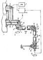
- 1 denotes the housing of a C0 2 laser, the beam of which is guided via an articulated arm to focusing optics 21 which can be moved by hand in several degrees of freedom and with which the beam is focused on the surface of an object 22 which is not specified in more detail .
- the articulated lens comprises a fixed tube 3 flanged to the housing 1, to which a second, telescopically extendable tube 4 is rotatably fastened via a first pivot bearing 24, a third also extendable tube 5, which in turn is fastened to part 4 via a second pivot bearing 25 is, and the cutting head 6, which contains the focusing optics 21 and is attached to the part 5 via a third rotary bearing 26.
- the arrows 14, 15 and 16 indicate that Direction of rotation of the bearings 24, 25 and 26 indicated, while the arrows 27 and 28 illustrate the telescopic extension of parts 4 and 5.
- the parts 4, 5 and 6 of the articulated arm are angled behind the respective pivot bearings 24, 25 and 26, about which they can be rotated with the parts following them, and contain deflection mirrors 17, 18 and 19, via which the laser beam is guided in the articulated arm is.
- the housing-fixed part 3 of the articulated arm contains a wavelength-selective beam splitter 10, via which the beam of a pilot laser 2 is coupled into the articulated arm coaxially to the beam of the working laser 1.
- This pilot lot 2 is used by the operator who guides the articulated arm to indicate the position of the focus of the invisible beam of the working laser 1 on the surface of the object 22.
- the mirror 6, via which the unemployed person 1 is brought into the focusing optics 21, is also designed as a beam splitter. It allows part of the radiation from the pilot laser 2 to pass through without reflection and thus strike a photoelectric quadrant detector 20 arranged behind it.
- the photosensitive surface of the detector 20 is divided into four sectors of equal size.
- the sectors of this detector emit constant light signals whose amplitudes do not differ from one another as long as the beam from the laser 2 hits the detector 20 centrally.
- the amplitude relationships of the constant light signals of the four quadrants change. This change is a measure of the amount of the emigration of the laser beam guided over the articulated arm from the axis of the articulated optics.
- An electronic circuit 13 evaluates the constant light signals and supplies an actuating signal for an actuating mirror 11 arranged at the input of the articulated arm. The deflection of the actuating mirror 11 compensates for the emigration of the laser beam.
- the positioning mirror 11 is attached to the housing-fixed part 13 via piezo elements 12.
- the deflection of the mirror 11 can also take place via, for example, inductive actuators, the only essential thing is that the adjustability of the mirror 11 in two coordinates is ge is guaranteed.
- Second positioning mirror 8 is provided, which is arranged in the beam path of the pilot laser 2 in front of the beam splitter 10.
- This positioning mirror 8 contains a piezoelectric bending oscillator 9, which is periodically excited by a generator 7 and thus modulates the beam of the auxiliary laser 2 with respect to its beam direction with a small amplitude.
- the sectors of the detector 20 supply an alternating light signal in addition to the sliding light signal, from whose amplitude ratio and phase position with respect to the output signal of the generator 7 the rotational position between the adjusting mirror 11 and the detector 20 can be determined.
- the electronic circuit 13 also performs this evaluation.
- the actuating signal for the mirror 11 which it outputs thus adjusts the latter in terms of amount and direction in such a way that the partial beam of the laser 2 passing through the splitter 19 strikes the detector 20 centrally.
- the circuit 13 for evaluating the direct and alternating light signals of the detector 20 can be implemented in various ways. The embodiment used depends, for example, on whether the modulation movement of the adjusting mirror 8 is linear or precessing.
- Exemplary embodiments for piezoelectric working mirrors include described in DE-PS 29 50 919.
Landscapes
- Physics & Mathematics (AREA)
- Optics & Photonics (AREA)
- Engineering & Computer Science (AREA)
- Health & Medical Sciences (AREA)
- Surgery (AREA)
- General Physics & Mathematics (AREA)
- Plasma & Fusion (AREA)
- Mechanical Engineering (AREA)
- Life Sciences & Earth Sciences (AREA)
- Biomedical Technology (AREA)
- Public Health (AREA)
- Nuclear Medicine, Radiotherapy & Molecular Imaging (AREA)
- Electromagnetism (AREA)
- Heart & Thoracic Surgery (AREA)
- Medical Informatics (AREA)
- Molecular Biology (AREA)
- Animal Behavior & Ethology (AREA)
- General Health & Medical Sciences (AREA)
- Otolaryngology (AREA)
- Veterinary Medicine (AREA)
- Laser Surgery Devices (AREA)
- Mechanical Light Control Or Optical Switches (AREA)
- Length Measuring Devices By Optical Means (AREA)
- Lasers (AREA)
- Radiation-Therapy Devices (AREA)
- Light Guides In General And Applications Therefor (AREA)
- Mechanical Optical Scanning Systems (AREA)
Applications Claiming Priority (2)
| Application Number | Priority Date | Filing Date | Title |
|---|---|---|---|
| DE19843406676 DE3406676A1 (de) | 1984-02-24 | 1984-02-24 | Einrichtung zur lagekorrektur eines ueber eine gelenkoptik gefuehrten laserstrahls |
| DE3406676 | 1984-02-24 |
Publications (2)
| Publication Number | Publication Date |
|---|---|
| EP0154865A1 true EP0154865A1 (fr) | 1985-09-18 |
| EP0154865B1 EP0154865B1 (fr) | 1987-11-19 |
Family
ID=6228682
Family Applications (1)
| Application Number | Title | Priority Date | Filing Date |
|---|---|---|---|
| EP85101962A Expired EP0154865B1 (fr) | 1984-02-24 | 1985-02-22 | Dispositif pour la correction d'alignement d'un faisceau laser passant un guide de lumière articulé |
Country Status (5)
| Country | Link |
|---|---|
| US (1) | US4659916A (fr) |
| EP (1) | EP0154865B1 (fr) |
| JP (1) | JPS60200220A (fr) |
| CA (1) | CA1248378A (fr) |
| DE (2) | DE3406676A1 (fr) |
Cited By (6)
| Publication number | Priority date | Publication date | Assignee | Title |
|---|---|---|---|---|
| EP0217077A3 (en) * | 1985-08-23 | 1988-01-27 | Firma Carl Zeiss | Device for correcting the position of a laser beam guided by an articulated optical system |
| EP0226428A3 (fr) * | 1985-12-06 | 1989-07-19 | Economair Pancan Limited | Dispositif de balayage par faisceau |
| US4855565A (en) * | 1986-03-25 | 1989-08-08 | Laser Lab Limited | Work head device |
| EP0453733A1 (fr) * | 1990-04-24 | 1991-10-30 | Daimler-Benz Aerospace Aktiengesellschaft | Méthode et dispositif de détection utilisés pour le réglage de position tridimensionnelle du foyer d'un laser à haute énergie |
| FR2696556A1 (fr) * | 1992-10-05 | 1994-04-08 | Peugeot | Procédé pour vérifier la présence et/ou la bonne orientation de miroirs d'acheminement d'un faisceau laser de puissance, dispositif pour la mise en Óoeuvre d'un tel procédé et capteur de lumière utilisé dans ce dispositif. |
| WO2009059010A1 (fr) * | 2007-10-30 | 2009-05-07 | Raytheon Company | Appareil d'orientation de faisceau ayant cinq degrés de liberté d'orientation de ligne de vue |
Families Citing this family (29)
| Publication number | Priority date | Publication date | Assignee | Title |
|---|---|---|---|---|
| DE3509378A1 (de) * | 1985-03-15 | 1986-09-18 | Binder, Karl-Franz, 8077 Reichertshofen | Bearbeitungsmaschine, wie brennschneidemaschine o.dgl. |
| JPS6417016A (en) * | 1987-07-11 | 1989-01-20 | Nec Corp | Optical wavelength multiplexer |
| JP2606227B2 (ja) * | 1987-09-04 | 1997-04-30 | 株式会社ニコン | 送光装置 |
| FR2627874B1 (fr) * | 1988-02-29 | 1995-06-16 | Framatome Sa | Systeme d'alignement d'un faisceau de puissance |
| US4917083A (en) * | 1988-03-04 | 1990-04-17 | Heraeus Lasersonics, Inc. | Delivery arrangement for a laser medical system |
| US4855564A (en) * | 1988-05-23 | 1989-08-08 | Westinghouse Electric Corp. | Laser beam alignment and transport system |
| JPH0290120A (ja) * | 1988-09-27 | 1990-03-29 | Shin Meiwa Ind Co Ltd | 可動ビーム照射装置 |
| US5034618A (en) * | 1989-09-05 | 1991-07-23 | Gmf Robotics Corporation | Method for aligning an articulated beam delivery device, such as a robot |
| US5011282A (en) * | 1989-11-16 | 1991-04-30 | Amada Company, Limited | Laser beam path alignment apparatus for laser processing machines |
| US5038015A (en) * | 1990-06-22 | 1991-08-06 | Robomatix Ltd. | End effector for translating in a cartesian coordinate system |
| DE4023224A1 (de) * | 1990-07-21 | 1992-01-30 | Heraeus Holding | Laser mit einem optischen resonator |
| US5536916A (en) * | 1994-09-30 | 1996-07-16 | Sanyo Machine Works, Ltd. | Method for performing automatic alignment-adjustment of laser robot and the device |
| US5705789A (en) * | 1995-09-29 | 1998-01-06 | Litel Instruments, Inc. | Stabilization of parallel transport mirror system |
| DE10058161C2 (de) * | 2000-11-22 | 2003-10-02 | Andreas Mueller | Laserkommunikationssystem |
| GB2370651B (en) * | 2000-12-18 | 2003-01-22 | Thyssen Laser Technik Gmbh | Laser robot for workpiece machining and method for workpiece machining with a laser robot |
| ITMI20031576A1 (it) * | 2003-07-31 | 2005-02-01 | Lucio Vaccani | Apparecchiatura di taglio o profilati ad elevata precisione di impiego. |
| CN101346800B (zh) * | 2005-12-20 | 2011-09-14 | 株式会社半导体能源研究所 | 用于制造半导体装置的激光辐射设备和方法 |
| US9371957B2 (en) * | 2005-12-21 | 2016-06-21 | Reliant Technologies, Llc | Articulated arm for delivering a laser beam |
| WO2007130313A2 (fr) * | 2006-05-02 | 2007-11-15 | Telesis Technologies, Inc. | Système de sécurité pour laser |
| DE102011115944B4 (de) * | 2011-10-08 | 2013-06-06 | Jenlab Gmbh | Flexibles nichtlineares Laserscanning-Mikroskop zur nicht-invasiven dreidimensionalen Detektion |
| US20150128717A1 (en) * | 2013-11-13 | 2015-05-14 | Gary J. May | Automated dynamic laser bond inspection system |
| JP6497896B2 (ja) * | 2014-11-18 | 2019-04-10 | キヤノン株式会社 | 情報取得装置 |
| CN107322158A (zh) * | 2017-08-15 | 2017-11-07 | 温州大学 | 导光臂 |
| DE202021002279U1 (de) | 2021-06-12 | 2021-07-12 | MOEWE Optical Solutions GmbH | Einrichtung zur Lagekorrektur eines Laserstrahls gepulster Stahlquellen in Verbindung mit einer Scannereinrichtung |
| DE102021003427B3 (de) | 2021-06-12 | 2022-11-17 | MOEWE Optical Solutions GmbH | Einrichtung zur Lagekorrektur eines Laserstrahls gepulster Strahlquellen in Verbindung mit einer Scannereinrichtung |
| AU2023371986A1 (en) * | 2022-11-02 | 2025-06-12 | Beijing Transcend Vivoscope Bio-Technology Co., Ltd. | Laser adapter, multiphoton microscope main unit and optical system |
| CN115598780B (zh) * | 2022-11-02 | 2025-08-19 | 北京大学 | 激光适配器及光学系统 |
| CN116652942A (zh) * | 2023-05-22 | 2023-08-29 | 中国铁建重工集团股份有限公司 | 一种多关节臂架的位姿检测与控制装置和方法 |
| CN120715413B (zh) * | 2025-08-25 | 2025-10-31 | 昆山新创博电子科技有限公司 | 一种激光雕刻机的光路聚焦装置 |
Citations (6)
| Publication number | Priority date | Publication date | Assignee | Title |
|---|---|---|---|---|
| DE2645393A1 (de) * | 1975-10-15 | 1977-04-21 | Philips Nv | Folgespiegelvorrichtung, insbesondere zum gebrauch in einem videoplattenspieler |
| US4129775A (en) * | 1977-05-31 | 1978-12-12 | Hughes Aircraft Company | Glint capture system for improving lock stability of coat |
| DE2757585B2 (de) * | 1976-12-24 | 1981-02-05 | Office National D'etudes Et De Recherches Aerospatiales O.N.E.R.A., Chatillon- Sous-Bagneux, Hauts-De-Seine (Frankreich) | Einrichtung zum selbsttätigen Ausrichten eines Laserstrahls auf ein Ziel |
| EP0048364A2 (fr) * | 1980-09-18 | 1982-03-31 | Erwin Sick GmbH Optik-Elektronik | Appareil de déviation de lumière piézoélectrique |
| DE3202432A1 (de) * | 1982-01-26 | 1983-08-04 | Messerschmitt-Bölkow-Blohm GmbH, 8000 München | Hochenergielaser-feintracker |
| US4473074A (en) * | 1981-09-28 | 1984-09-25 | Xanar, Inc. | Microsurgical laser device |
Family Cites Families (9)
| Publication number | Priority date | Publication date | Assignee | Title |
|---|---|---|---|---|
| US3902036A (en) * | 1974-05-02 | 1975-08-26 | Western Electric Co | Control system using multiplexed laser beams |
| JPS5827891B2 (ja) * | 1976-09-14 | 1983-06-13 | 日本ビクター株式会社 | レ−ザ光束の安定化装置 |
| US4279472A (en) * | 1977-12-05 | 1981-07-21 | Street Graham S B | Laser scanning apparatus with beam position correction |
| US4271334A (en) * | 1979-04-06 | 1981-06-02 | Discovision Associates | Apparatus for correcting for temperature-induced tracking errors in a system for recovering information from a recording disc |
| US4349732A (en) * | 1980-01-07 | 1982-09-14 | The Singer Company | Laser spatial stabilization transmission system |
| JPS589227A (ja) * | 1981-07-07 | 1983-01-19 | Mitsubishi Electric Corp | 光学的サ−ボ装置 |
| FR2511537B1 (fr) * | 1981-08-14 | 1986-09-05 | Thomson Csf | Dispositif optique de suivi de piste a echantillonnage |
| US4429211A (en) * | 1982-08-02 | 1984-01-31 | United Technologies Corporation | Laser pipe welding system for nonstationary pipe |
| US5810076A (en) * | 1996-03-06 | 1998-09-22 | Solar Turbines Incorporated | High pressure ceramic heat exchanger |
-
1984
- 1984-02-24 DE DE19843406676 patent/DE3406676A1/de not_active Withdrawn
-
1985
- 1985-02-13 US US06/701,168 patent/US4659916A/en not_active Expired - Fee Related
- 1985-02-20 CA CA000474764A patent/CA1248378A/fr not_active Expired
- 1985-02-22 JP JP60032970A patent/JPS60200220A/ja active Pending
- 1985-02-22 EP EP85101962A patent/EP0154865B1/fr not_active Expired
- 1985-02-22 DE DE8585101962T patent/DE3560983D1/de not_active Expired
Patent Citations (6)
| Publication number | Priority date | Publication date | Assignee | Title |
|---|---|---|---|---|
| DE2645393A1 (de) * | 1975-10-15 | 1977-04-21 | Philips Nv | Folgespiegelvorrichtung, insbesondere zum gebrauch in einem videoplattenspieler |
| DE2757585B2 (de) * | 1976-12-24 | 1981-02-05 | Office National D'etudes Et De Recherches Aerospatiales O.N.E.R.A., Chatillon- Sous-Bagneux, Hauts-De-Seine (Frankreich) | Einrichtung zum selbsttätigen Ausrichten eines Laserstrahls auf ein Ziel |
| US4129775A (en) * | 1977-05-31 | 1978-12-12 | Hughes Aircraft Company | Glint capture system for improving lock stability of coat |
| EP0048364A2 (fr) * | 1980-09-18 | 1982-03-31 | Erwin Sick GmbH Optik-Elektronik | Appareil de déviation de lumière piézoélectrique |
| US4473074A (en) * | 1981-09-28 | 1984-09-25 | Xanar, Inc. | Microsurgical laser device |
| DE3202432A1 (de) * | 1982-01-26 | 1983-08-04 | Messerschmitt-Bölkow-Blohm GmbH, 8000 München | Hochenergielaser-feintracker |
Non-Patent Citations (2)
| Title |
|---|
| PATENT ABSTRACTS OF JAPAN, Band 5, Nr. 131, 21. August 1981, Seite (M-84) (803); & JP-A-56-66395 (SUMITOMO DENKI KOGYO K.K.) 04-06-1981 * |
| PATENT ABSTRACTS OF JAPAN, Band 7, Nr. 6, 11. Januar 1983, Seite (P-167) (1151); & JP-A-57-164445 (FUJITSU K.K.) 09-10-1982 * |
Cited By (7)
| Publication number | Priority date | Publication date | Assignee | Title |
|---|---|---|---|---|
| EP0217077A3 (en) * | 1985-08-23 | 1988-01-27 | Firma Carl Zeiss | Device for correcting the position of a laser beam guided by an articulated optical system |
| EP0226428A3 (fr) * | 1985-12-06 | 1989-07-19 | Economair Pancan Limited | Dispositif de balayage par faisceau |
| US4855565A (en) * | 1986-03-25 | 1989-08-08 | Laser Lab Limited | Work head device |
| EP0453733A1 (fr) * | 1990-04-24 | 1991-10-30 | Daimler-Benz Aerospace Aktiengesellschaft | Méthode et dispositif de détection utilisés pour le réglage de position tridimensionnelle du foyer d'un laser à haute énergie |
| FR2696556A1 (fr) * | 1992-10-05 | 1994-04-08 | Peugeot | Procédé pour vérifier la présence et/ou la bonne orientation de miroirs d'acheminement d'un faisceau laser de puissance, dispositif pour la mise en Óoeuvre d'un tel procédé et capteur de lumière utilisé dans ce dispositif. |
| WO2009059010A1 (fr) * | 2007-10-30 | 2009-05-07 | Raytheon Company | Appareil d'orientation de faisceau ayant cinq degrés de liberté d'orientation de ligne de vue |
| US7648249B2 (en) | 2007-10-30 | 2010-01-19 | Raytheon Company | Beam-steering apparatus having five degrees of freedom of line-of-sight steering |
Also Published As
| Publication number | Publication date |
|---|---|
| CA1248378A (fr) | 1989-01-10 |
| DE3560983D1 (en) | 1987-12-23 |
| DE3406676A1 (de) | 1985-09-05 |
| JPS60200220A (ja) | 1985-10-09 |
| US4659916A (en) | 1987-04-21 |
| EP0154865B1 (fr) | 1987-11-19 |
Similar Documents
| Publication | Publication Date | Title |
|---|---|---|
| EP0154865B1 (fr) | Dispositif pour la correction d'alignement d'un faisceau laser passant un guide de lumière articulé | |
| EP0217077B1 (fr) | Dispositif pour la correction de position d'un faisceau laser guidé par une optique articulée | |
| EP0154866B1 (fr) | Dispositif pour la compensation de la déviation d'un faisceau laser | |
| EP0367924B1 (fr) | Procédé et dispositif pour déterminer la position d'un joint d'une soudure pour le soudage à laser | |
| DE4202505B4 (de) | Führungssystem zum räumlichen Positionieren eines chirurgischen Instrumentes, insbesondere eines Operationsmikroskops | |
| EP1716963B1 (fr) | Optiques pour le le travail à distance au laser permettant la création d'un espace de travail 3D | |
| DE69103744T2 (de) | Bildverarbeitungseinrichtung. | |
| DE3445751C2 (fr) | ||
| EP3837779B1 (fr) | Structure de réception d'un signal de données optique | |
| DE69109852T2 (de) | Ausrichtungskontrollvorrichtung und ihre verwendung. | |
| EP1101142B1 (fr) | Procede et dispositif pour detecter la position d'un plan a explorer par balayage au laser | |
| EP0271646A1 (fr) | Dispositif de mesure sans contact d'une distance d'une surface, en particulier pour palper un contour d'une surface d'une pièce d'oeuvre le long d'une trajectoire de mesure | |
| DE4202606C2 (de) | Vorrichtung zum Fokussieren eines Lichtbündels in mehreren Fokuspunkten | |
| DE4039318A1 (de) | Einrichtung zur erfassung der hoehenlage einer laserbearbeitungsvorrichtung bezueglich eines werkstuecks | |
| DE3935239A1 (de) | Abtastgeraet | |
| EP0098244A1 (fr) | Procédé et dispositif de mise au point d'un rayon de lumière sur un objet | |
| DE69410336T2 (de) | Spiegellage und -richtungs Kontrollvorrichtung | |
| EP0102466B1 (fr) | Dispositif pour le balayage optomécanique d'un champ visuel de manière passive et active | |
| EP0242858A2 (fr) | Méthode et système pour corriger les erreurs de positionnement pour les bras de robots | |
| EP0287648B1 (fr) | Systeme d'exploration par rayons | |
| DE19914984B4 (de) | Vorrichtung zum Feststellen der Lage eines Arbeitsfokus relativ zu einer Oberfläche eines zu bearbeitenden Werkstücks in einer Laserbearbeitungsanlage | |
| DE4122623C2 (de) | Steuerungseinrichtung zur Strahlnachführung | |
| DE69014908T2 (de) | Achromatisches optisches Laserabtastsystem. | |
| DE102018100414B4 (de) | Verfahren und Vorrichtung zur optischen Zielverfolgung von mit einem Hochenergielaser bestrahlbarem Zielobjekt | |
| DE102019213521A1 (de) | Aufbau zum Empfangen eines optischen Datensignals |
Legal Events
| Date | Code | Title | Description |
|---|---|---|---|
| PUAI | Public reference made under article 153(3) epc to a published international application that has entered the european phase |
Free format text: ORIGINAL CODE: 0009012 |
|
| AK | Designated contracting states |
Designated state(s): CH DE FR GB LI SE |
|
| 17P | Request for examination filed |
Effective date: 19851127 |
|
| RAP1 | Party data changed (applicant data changed or rights of an application transferred) |
Owner name: CARL-ZEISS-STIFTUNG TRADING AS CARL ZEISS Owner name: FIRMA CARL ZEISS |
|
| 17Q | First examination report despatched |
Effective date: 19870414 |
|
| GRAA | (expected) grant |
Free format text: ORIGINAL CODE: 0009210 |
|
| AK | Designated contracting states |
Kind code of ref document: B1 Designated state(s): CH DE FR GB LI SE |
|
| REF | Corresponds to: |
Ref document number: 3560983 Country of ref document: DE Date of ref document: 19871223 |
|
| ET | Fr: translation filed | ||
| GBT | Gb: translation of ep patent filed (gb section 77(6)(a)/1977) | ||
| REG | Reference to a national code |
Ref country code: CH Ref legal event code: PK |
|
| PLBE | No opposition filed within time limit |
Free format text: ORIGINAL CODE: 0009261 |
|
| STAA | Information on the status of an ep patent application or granted ep patent |
Free format text: STATUS: NO OPPOSITION FILED WITHIN TIME LIMIT |
|
| RAP2 | Party data changed (patent owner data changed or rights of a patent transferred) |
Owner name: CARL-ZEISS-STIFTUNG TRADING AS CARL ZEISS Owner name: FIRMA CARL ZEISS |
|
| 26N | No opposition filed | ||
| PGFP | Annual fee paid to national office [announced via postgrant information from national office to epo] |
Ref country code: GB Payment date: 19910131 Year of fee payment: 7 Ref country code: CH Payment date: 19910131 Year of fee payment: 7 |
|
| PGFP | Annual fee paid to national office [announced via postgrant information from national office to epo] |
Ref country code: SE Payment date: 19910206 Year of fee payment: 7 |
|
| PGFP | Annual fee paid to national office [announced via postgrant information from national office to epo] |
Ref country code: FR Payment date: 19910214 Year of fee payment: 7 |
|
| PG25 | Lapsed in a contracting state [announced via postgrant information from national office to epo] |
Ref country code: GB Effective date: 19920222 |
|
| PG25 | Lapsed in a contracting state [announced via postgrant information from national office to epo] |
Ref country code: SE Effective date: 19920223 |
|
| PG25 | Lapsed in a contracting state [announced via postgrant information from national office to epo] |
Ref country code: LI Effective date: 19920229 Ref country code: CH Effective date: 19920229 |
|
| GBPC | Gb: european patent ceased through non-payment of renewal fee | ||
| PG25 | Lapsed in a contracting state [announced via postgrant information from national office to epo] |
Ref country code: FR Effective date: 19921030 |
|
| REG | Reference to a national code |
Ref country code: CH Ref legal event code: PL |
|
| REG | Reference to a national code |
Ref country code: FR Ref legal event code: ST |
|
| EUG | Se: european patent has lapsed |
Ref document number: 85101962.0 Effective date: 19920904 |
|
| PGFP | Annual fee paid to national office [announced via postgrant information from national office to epo] |
Ref country code: DE Payment date: 19970124 Year of fee payment: 13 |
|
| PG25 | Lapsed in a contracting state [announced via postgrant information from national office to epo] |
Ref country code: DE Free format text: LAPSE BECAUSE OF NON-PAYMENT OF DUE FEES Effective date: 19981103 |