EP0453733A1 - Méthode et dispositif de détection utilisés pour le réglage de position tridimensionnelle du foyer d'un laser à haute énergie - Google Patents
Méthode et dispositif de détection utilisés pour le réglage de position tridimensionnelle du foyer d'un laser à haute énergie Download PDFInfo
- Publication number
- EP0453733A1 EP0453733A1 EP91102915A EP91102915A EP0453733A1 EP 0453733 A1 EP0453733 A1 EP 0453733A1 EP 91102915 A EP91102915 A EP 91102915A EP 91102915 A EP91102915 A EP 91102915A EP 0453733 A1 EP0453733 A1 EP 0453733A1
- Authority
- EP
- European Patent Office
- Prior art keywords
- laser beam
- quadrant detector
- focused
- focus
- section
- Prior art date
- Legal status (The legal status is an assumption and is not a legal conclusion. Google has not performed a legal analysis and makes no representation as to the accuracy of the status listed.)
- Granted
Links
- 238000000034 method Methods 0.000 title claims abstract description 8
- 230000003287 optical effect Effects 0.000 claims abstract description 7
- 230000004075 alteration Effects 0.000 claims abstract description 6
- 238000005259 measurement Methods 0.000 claims abstract description 3
- 238000003913 materials processing Methods 0.000 abstract 1
- 230000005540 biological transmission Effects 0.000 description 4
- 238000012937 correction Methods 0.000 description 3
- 238000012545 processing Methods 0.000 description 3
- 238000010586 diagram Methods 0.000 description 2
- 238000011156 evaluation Methods 0.000 description 2
- 230000003044 adaptive effect Effects 0.000 description 1
- 238000013461 design Methods 0.000 description 1
- 238000003745 diagnosis Methods 0.000 description 1
- RVRCFVVLDHTFFA-UHFFFAOYSA-N heptasodium;tungsten;nonatriacontahydrate Chemical compound O.O.O.O.O.O.O.O.O.O.O.O.O.O.O.O.O.O.O.O.O.O.O.O.O.O.O.O.O.O.O.O.O.O.O.O.O.O.O.[Na+].[Na+].[Na+].[Na+].[Na+].[Na+].[Na+].[W].[W].[W].[W].[W].[W].[W].[W].[W].[W].[W] RVRCFVVLDHTFFA-UHFFFAOYSA-N 0.000 description 1
Images


Classifications
-
- B—PERFORMING OPERATIONS; TRANSPORTING
- B23—MACHINE TOOLS; METAL-WORKING NOT OTHERWISE PROVIDED FOR
- B23K—SOLDERING OR UNSOLDERING; WELDING; CLADDING OR PLATING BY SOLDERING OR WELDING; CUTTING BY APPLYING HEAT LOCALLY, e.g. FLAME CUTTING; WORKING BY LASER BEAM
- B23K26/00—Working by laser beam, e.g. welding, cutting or boring
- B23K26/02—Positioning or observing the workpiece, e.g. with respect to the point of impact; Aligning, aiming or focusing the laser beam
- B23K26/04—Automatically aligning, aiming or focusing the laser beam, e.g. using the back-scattered light
Definitions
- the invention relates to a method for three-dimensional position control of the focal point of a high-energy laser beam while measuring the tilt and focal length deviation of the laser beam and a device for carrying it out.
- Fig. 1 shows a schematic representation of the optical part of the device according to the invention. This consists of a beam splitter ST, a focusing arrangement L with an aperture B and a lens pair or system V / Z and a quadrant detector Q.
- the beam S first strikes the beam splitter ST and is split by it into a working beam S a and a measuring beam S m .
- the beams are focused in transmission and a diffraction pattern determined by the lattice structure of the holes is obtained.
- the main part goes into the zero order; the next orders only account for a few percent: where P R is the power in the different orders, P O is the total irradiated power and R is the reflection coefficient.
- the beam is focused with a spherical lens L behind the beam splitter ST. In focus, the higher orders are hidden with a square pinhole B.
- V / Z With the following lens combination V / Z the image is enlarged and an astigmatic aberration is introduced, as for example in Bricot, C., Lehureau, JC, Puech, C., Le Carvennec, F. (1976), IEEE Trans. Consumer Electron. CE-22, 304 is described. As shown in FIG. 2, this results in two different focal points in the x and y directions, namely the meridional focal point F m and the sagittal focal point F s . In between is the point of greatest sharpness F. There is a quadrant detector Q with four sectors S1 ... S4 arranged.
- the signals at the output of the quadrant detector are designated Q1 ... Q4.
- the correction values for the control mechanism are K Tx , K Tx and K F and serve to adjust the x and y tilt or the focus. They are calculated as follows:
- the tilt must first be compensated for with the corresponding actuator before the focus can be corrected, since the focus correction is based on a beam that is not tilted.
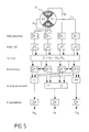
- FIG. 6 shows a block diagram of the electronics used for evaluation.
- the signals Q1 ... Q4 coming from the quadrant detector Q with the sectors S1 ... S4 are amplified individually, for example with operational amplifiers. This is followed by a band filter, the is tuned to the frequency of the measuring chopper. This is expediently introduced into the beam path in the vicinity of the aperture B. This combination of measuring chopper and filter amplifier serves to increase the signal-to-noise ratio and is also required for physical reasons in the pyroelectric detector used in the exemplary embodiment.
- the signals are then converted into a DC voltage signal using voltage-controlled rectifiers (RMS / DC converters). All signals Q1 ... Q4 are summed by means of an operational amplifier. Standardized signals are generated with the aid of analog dividers.
- An analog arithmetic unit follows, which is also constructed from operational amplifiers and determines the correction variables K F , K Tx , K Ty . These are amplified in a power amplifier stage.
- the beam diameter should be up to 50 mm.
- the beam splitter ST should be used at an angle of 5 °. In principle, the distance between the bores in one direction should be somewhat larger. However, the error is less than 1% at 5 °.
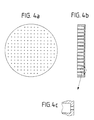
- the dimensions can be seen from FIG.
- the diameter of the beam splitter is 55 mm, the distance between the holes is 3 mm and the diameter of the two-stage holes on the inlet side (depth 9 mm) is 1.5 mm and 0.5 mm on the outlet side (depth 1 mm).
- the beam splitter is 10 mm thick. The positioning of the holes is chosen so that a hole is in the center.
- the converging lens L with a focal length of f F is arranged as close as possible behind the beam splitter ST.
- the square pinhole B comes into focus precisely in such a way that it only lets the 0th order through.
- the inside diameter is 1.6 mm.
- the lenses V and Z are arranged in direct succession, so that the following formula applies to the calculation: where f m represents the meridional and f s the sagittal focus. The mean focus is therefore about 95 mm.
- the object width g is 142.5 mm and the average image width b is 285 mm.
- the lens combination V / Z is placed at a distance g from the aperture B; the detector Q at a distance b from the lenses V / Z.
- the meridional and sagittal image widths are referred to as b m and b s .
- the detector With a variation of the object width of a little less than 10 mm, the detector remains between the meridional and the sagittal image. This is necessary in order to always get a correct control signal.
- a pyroelectric quadrant detector with an active area of + 2 mm in each direction is used as the detector.
- a 200 Hz chopper comes in front of the detector. As described above, this is used to chop the measurement signal.
Landscapes
- Physics & Mathematics (AREA)
- Optics & Photonics (AREA)
- Engineering & Computer Science (AREA)
- Plasma & Fusion (AREA)
- Mechanical Engineering (AREA)
- Length Measuring Devices By Optical Means (AREA)
- Photometry And Measurement Of Optical Pulse Characteristics (AREA)
- Laser Beam Processing (AREA)
Applications Claiming Priority (2)
| Application Number | Priority Date | Filing Date | Title |
|---|---|---|---|
| DE4012927 | 1990-04-24 | ||
| DE4012927A DE4012927C2 (de) | 1990-04-24 | 1990-04-24 | Meß-Verfahren und -Vorrichtung zur dreidimensionalen Lageregelung des Brennpunktes eines Hochenergie-Laserstrahls |
Publications (2)
| Publication Number | Publication Date |
|---|---|
| EP0453733A1 true EP0453733A1 (fr) | 1991-10-30 |
| EP0453733B1 EP0453733B1 (fr) | 1994-05-04 |
Family
ID=6404917
Family Applications (1)
| Application Number | Title | Priority Date | Filing Date |
|---|---|---|---|
| EP91102915A Expired - Lifetime EP0453733B1 (fr) | 1990-04-24 | 1991-02-28 | Méthode et dispositif de détection utilisés pour le réglage de position tridimensionnelle du foyer d'un laser à haute énergie |
Country Status (4)
| Country | Link |
|---|---|
| US (1) | US5166505A (fr) |
| EP (1) | EP0453733B1 (fr) |
| JP (1) | JPH04226417A (fr) |
| DE (2) | DE4012927C2 (fr) |
Cited By (9)
| Publication number | Priority date | Publication date | Assignee | Title |
|---|---|---|---|---|
| WO1995027188A1 (fr) * | 1994-04-05 | 1995-10-12 | British Nuclear Fuels Plc | Capteur de position d'un faisceau de rayonnement |
| US5653900A (en) * | 1991-01-17 | 1997-08-05 | United Distillers Plc | Dynamic laser marking |
| DE19720832A1 (de) * | 1997-05-17 | 1998-11-19 | Diehl Stiftung & Co | Zielerfassungsvorrichtung |
| US6791592B2 (en) | 2000-04-18 | 2004-09-14 | Laserink | Printing a code on a product |
| WO2004098004A3 (fr) * | 2003-04-24 | 2005-02-24 | Coherent Inc | Systeme de detection pour pointage et mise en forme d'un faisceau optique |
| US7046267B2 (en) | 2003-12-19 | 2006-05-16 | Markem Corporation | Striping and clipping correction |
| US7394479B2 (en) | 2005-03-02 | 2008-07-01 | Marken Corporation | Pulsed laser printing |
| US10583668B2 (en) | 2018-08-07 | 2020-03-10 | Markem-Imaje Corporation | Symbol grouping and striping for wide field matrix laser marking |
| US11612954B2 (en) | 2017-08-03 | 2023-03-28 | TRUMPF Werkzeugmaschinen SE + Co. KG | Laser-beam material machining |
Families Citing this family (12)
| Publication number | Priority date | Publication date | Assignee | Title |
|---|---|---|---|---|
| DE4123052A1 (de) * | 1990-09-13 | 1992-03-19 | Messerschmitt Boelkow Blohm | Integriertes sensor- und stellelement fuer die brennpunktlageregelung von hochleistungslasern |
| GB9611942D0 (en) * | 1996-06-07 | 1996-08-07 | Lumonics Ltd | Focus control of lasers in material processing operations |
| US5831736A (en) * | 1996-08-29 | 1998-11-03 | Washington University | Method and apparatus for generating a three-dimensional topographical image of a microscopic specimen |
| US6476353B2 (en) | 2000-01-26 | 2002-11-05 | Js Chamberlain & Assoc. | Laser surface finishing apparatus and method |
| EP1649964A1 (fr) * | 2004-10-25 | 2006-04-26 | Trumpf Werkzeugmaschinen GmbH + Co. KG | Dispositif de détermination de la position d'un rayon laser |
| CA2580102A1 (fr) * | 2006-03-06 | 2007-09-06 | General Electric Company | Systeme et methode permettant de controler les parametres de forage et de commander le forage |
| WO2008157411A1 (fr) * | 2007-06-14 | 2008-12-24 | Kansas State University Research Foundation | Appareil de précipitation à lit fluidisé |
| US8203703B1 (en) * | 2010-03-18 | 2012-06-19 | ARETé ASSOCIATES | Image null-balance system with multisector-cell direction sensing |
| EP3524408A1 (fr) * | 2018-02-07 | 2019-08-14 | CL Schutzrechtsverwaltungs GmbH | Appareil de fabrication additive d'objets tridimensionnels |
| EP3524410B8 (fr) * | 2018-02-07 | 2023-05-03 | Concept Laser GmbH | Appareil de fabrication additive d'objets tridimensionnels |
| DE102018105364B4 (de) * | 2018-03-08 | 2020-06-25 | Precitec Gmbh & Co. Kg | Vorrichtung zur Bestimmung einer Fokuslage eines Laserstrahls in einem Laserbearbeitungssystem, Laserbearbeitungssystem mit derselben und Verfahren zur Bestimmung einer Fokuslage eines Laserstrahls in einem Laserbearbeitungssystem |
| CN112433365B (zh) * | 2020-11-17 | 2022-02-11 | 中国科学院西安光学精密机械研究所 | 一种基于锥镜的光束指向控制系统的偏差修正方法 |
Citations (4)
| Publication number | Priority date | Publication date | Assignee | Title |
|---|---|---|---|---|
| EP0075192A2 (fr) * | 1981-09-17 | 1983-03-30 | Kabushiki Kaisha Toshiba | Une tête optique |
| EP0154865A1 (fr) * | 1984-02-24 | 1985-09-18 | Firma Carl Zeiss | Dispositif pour la correction d'alignement d'un faisceau laser passant un guide de lumière articulé |
| GB2158228A (en) * | 1984-05-05 | 1985-11-06 | Spectron Dev Lab Inc | Astigmatic non-contact optical probe |
| GB2184831A (en) * | 1985-12-20 | 1987-07-01 | Atomic Energy Authority Uk | Radiation beam position sensor |
Family Cites Families (8)
| Publication number | Priority date | Publication date | Assignee | Title |
|---|---|---|---|---|
| US3296594A (en) * | 1963-06-14 | 1967-01-03 | Polaroid Corp | Optical associative memory |
| US4742219A (en) * | 1981-09-17 | 1988-05-03 | Tokyo Shibaura Denki Kabushiki Kaisha | Apparatus for detecting the focusing state and positional accuracy of a light beam directed onto an optical disk tracking guide in an optical read/write system |
| DE3202432C2 (de) * | 1982-01-26 | 1987-04-23 | Messerschmitt-Bölkow-Blohm GmbH, 8000 München | Hochenergielaser-Feintracker |
| DE3406677A1 (de) * | 1984-02-24 | 1985-09-05 | Fa. Carl Zeiss, 7920 Heidenheim | Einrichtung zur kompensation der auswanderung eines laserstrahls |
| US4731772A (en) * | 1986-05-06 | 1988-03-15 | Lee Wai Hon | Optical head using hologram lens for both beam splitting and focus error detection functions |
| NL8603108A (nl) * | 1986-12-08 | 1988-07-01 | Philips Nv | Mikroskoop. |
| EP0311340B1 (fr) * | 1987-10-05 | 1993-08-04 | Matsushita Electric Industrial Co., Ltd. | Tête de lecture optique |
| DE3800427C2 (de) * | 1988-01-09 | 1997-05-28 | Breitmeier Ulrich | Gerät zum Ermitteln des Abstands eines auf einer Prüffläche liegenden Prüfpunktes von einer Referenzfläche |
-
1990
- 1990-04-24 DE DE4012927A patent/DE4012927C2/de not_active Expired - Fee Related
-
1991
- 1991-02-28 DE DE59101541T patent/DE59101541D1/de not_active Expired - Fee Related
- 1991-02-28 EP EP91102915A patent/EP0453733B1/fr not_active Expired - Lifetime
- 1991-04-24 US US07/690,270 patent/US5166505A/en not_active Expired - Fee Related
- 1991-04-24 JP JP3094272A patent/JPH04226417A/ja not_active Withdrawn
Patent Citations (4)
| Publication number | Priority date | Publication date | Assignee | Title |
|---|---|---|---|---|
| EP0075192A2 (fr) * | 1981-09-17 | 1983-03-30 | Kabushiki Kaisha Toshiba | Une tête optique |
| EP0154865A1 (fr) * | 1984-02-24 | 1985-09-18 | Firma Carl Zeiss | Dispositif pour la correction d'alignement d'un faisceau laser passant un guide de lumière articulé |
| GB2158228A (en) * | 1984-05-05 | 1985-11-06 | Spectron Dev Lab Inc | Astigmatic non-contact optical probe |
| GB2184831A (en) * | 1985-12-20 | 1987-07-01 | Atomic Energy Authority Uk | Radiation beam position sensor |
Cited By (13)
| Publication number | Priority date | Publication date | Assignee | Title |
|---|---|---|---|---|
| US5653900A (en) * | 1991-01-17 | 1997-08-05 | United Distillers Plc | Dynamic laser marking |
| WO1995027188A1 (fr) * | 1994-04-05 | 1995-10-12 | British Nuclear Fuels Plc | Capteur de position d'un faisceau de rayonnement |
| US5939704A (en) * | 1994-04-05 | 1999-08-17 | British Nuclear Fuels Plc | Radiation beam position sensor |
| DE19720832A1 (de) * | 1997-05-17 | 1998-11-19 | Diehl Stiftung & Co | Zielerfassungsvorrichtung |
| DE19720832C2 (de) * | 1997-05-17 | 2003-02-27 | Diehl Stiftung & Co | Zielerfassungsvorrichtung |
| US6829000B2 (en) | 2000-04-18 | 2004-12-07 | Laserink | Printing a code on a product |
| US6791592B2 (en) | 2000-04-18 | 2004-09-14 | Laserink | Printing a code on a product |
| US7167194B2 (en) | 2000-04-18 | 2007-01-23 | Laserink | Printing a code on a product |
| WO2004098004A3 (fr) * | 2003-04-24 | 2005-02-24 | Coherent Inc | Systeme de detection pour pointage et mise en forme d'un faisceau optique |
| US7046267B2 (en) | 2003-12-19 | 2006-05-16 | Markem Corporation | Striping and clipping correction |
| US7394479B2 (en) | 2005-03-02 | 2008-07-01 | Marken Corporation | Pulsed laser printing |
| US11612954B2 (en) | 2017-08-03 | 2023-03-28 | TRUMPF Werkzeugmaschinen SE + Co. KG | Laser-beam material machining |
| US10583668B2 (en) | 2018-08-07 | 2020-03-10 | Markem-Imaje Corporation | Symbol grouping and striping for wide field matrix laser marking |
Also Published As
| Publication number | Publication date |
|---|---|
| JPH04226417A (ja) | 1992-08-17 |
| DE4012927A1 (de) | 1991-10-31 |
| DE4012927C2 (de) | 1995-10-12 |
| EP0453733B1 (fr) | 1994-05-04 |
| US5166505A (en) | 1992-11-24 |
| DE59101541D1 (de) | 1994-06-09 |
Similar Documents
| Publication | Publication Date | Title |
|---|---|---|
| EP0453733B1 (fr) | Méthode et dispositif de détection utilisés pour le réglage de position tridimensionnelle du foyer d'un laser à haute énergie | |
| DE102019004337B4 (de) | Optisches System und Strahlanalyseverfahren | |
| DE3610530C2 (fr) | ||
| EP0168351B1 (fr) | Générateur laser de motifs et procédé pour son emploi | |
| DE3110287C2 (fr) | ||
| DE3879790T2 (de) | Optisches rastermikroskop. | |
| DE2643975A1 (de) | Optischer fokussierungsmessfuehler und damit ausgeruestete fokussierungsvorrichtung | |
| EP1716963A1 (fr) | Optiques pour le le travail à distance au laser permettant la création d'un espace de travail 3D | |
| WO2021069362A1 (fr) | Dispositif d'ajustement pour un système optique d'usinage par faisceau de bessel et procédé correspondant | |
| DE3326636A1 (de) | Optisches peilsystem | |
| DE2034341C3 (de) | Vorrichtung zur Materialbearbeitung mittels Laserstrahlen | |
| EP1333304B1 (fr) | Modul de mise au point automatique comprennant des sources de lumière auxiliaires pour des systèmes à microscope et méthode de mise au point automatique à deux faiseaux utilisant ce module | |
| DE69721378T2 (de) | Laserfokussierungssteuerung in Verarbeitungsoperationen von Materialien | |
| WO2022128995A1 (fr) | Dispositif et procédé pour déterminer des positions focales | |
| DE102022118147A1 (de) | Laserbearbeitungskopf und Verfahren zum Bearbeiten eines Werkstücks | |
| DE2328069A1 (de) | Optische ablenkvorrichtung und deren anwendung bei holographischen speichern | |
| DE19961918C2 (de) | Variables Doppelfokusformungsmodul und Verfahren zu seiner Anwendung | |
| DE2505774C3 (de) | Justiervorrichtung für eine Laseranordnung aus einem Leistungslaser und einem Justierlaser | |
| DE19619481C1 (de) | Verfahren und Vorrichtung zum Abtragen von Material mit einem Laserstrahl | |
| DE69320018T2 (de) | Vorrichtung zur optischen Abtastung einer Fläche | |
| DE102008035898A1 (de) | Vorrichtung und Verfahren zur Specklereduktion im Bereich der Laseranwendungen | |
| DE19914984B4 (de) | Vorrichtung zum Feststellen der Lage eines Arbeitsfokus relativ zu einer Oberfläche eines zu bearbeitenden Werkstücks in einer Laserbearbeitungsanlage | |
| EP0128993B1 (fr) | Procédé de détermination de références pour la correction de mouvements mécaniques lors de l'écriture de lignes dans une trame métallisée à l'aide d'un laser ainsi que l'appareil pour réaliser ce procédé | |
| DE3635840A1 (de) | Mit strahlen abtastendes abtastsystem | |
| WO2023208863A1 (fr) | Appareil et procédé de détermination d'une position focale en fonction d'un gaz de traitement |
Legal Events
| Date | Code | Title | Description |
|---|---|---|---|
| PUAI | Public reference made under article 153(3) epc to a published international application that has entered the european phase |
Free format text: ORIGINAL CODE: 0009012 |
|
| AK | Designated contracting states |
Kind code of ref document: A1 Designated state(s): DE FR GB IT |
|
| 17P | Request for examination filed |
Effective date: 19910926 |
|
| 17Q | First examination report despatched |
Effective date: 19921123 |
|
| RAP1 | Party data changed (applicant data changed or rights of an application transferred) |
Owner name: DEUTSCHE AEROSPACE AKTIENGESELLSCHAFT |
|
| GRAA | (expected) grant |
Free format text: ORIGINAL CODE: 0009210 |
|
| AK | Designated contracting states |
Kind code of ref document: B1 Designated state(s): DE FR GB IT |
|
| REF | Corresponds to: |
Ref document number: 59101541 Country of ref document: DE Date of ref document: 19940609 |
|
| ITF | It: translation for a ep patent filed | ||
| GBT | Gb: translation of ep patent filed (gb section 77(6)(a)/1977) |
Effective date: 19940705 |
|
| ET | Fr: translation filed | ||
| PLBE | No opposition filed within time limit |
Free format text: ORIGINAL CODE: 0009261 |
|
| STAA | Information on the status of an ep patent application or granted ep patent |
Free format text: STATUS: NO OPPOSITION FILED WITHIN TIME LIMIT |
|
| RAP2 | Party data changed (patent owner data changed or rights of a patent transferred) |
Owner name: DAIMLER-BENZ AEROSPACE AKTIENGESELLSCHAFT |
|
| 26N | No opposition filed | ||
| PGFP | Annual fee paid to national office [announced via postgrant information from national office to epo] |
Ref country code: DE Payment date: 19960223 Year of fee payment: 6 |
|
| PGFP | Annual fee paid to national office [announced via postgrant information from national office to epo] |
Ref country code: FR Payment date: 19970716 Year of fee payment: 7 |
|
| PGFP | Annual fee paid to national office [announced via postgrant information from national office to epo] |
Ref country code: GB Payment date: 19970722 Year of fee payment: 7 |
|
| PG25 | Lapsed in a contracting state [announced via postgrant information from national office to epo] |
Ref country code: DE Effective date: 19971101 |
|
| PG25 | Lapsed in a contracting state [announced via postgrant information from national office to epo] |
Ref country code: GB Free format text: LAPSE BECAUSE OF NON-PAYMENT OF DUE FEES Effective date: 19980228 Ref country code: FR Free format text: THE PATENT HAS BEEN ANNULLED BY A DECISION OF A NATIONAL AUTHORITY Effective date: 19980228 |
|
| GBPC | Gb: european patent ceased through non-payment of renewal fee |
Effective date: 19980228 |
|
| REG | Reference to a national code |
Ref country code: FR Ref legal event code: ST |
|
| PG25 | Lapsed in a contracting state [announced via postgrant information from national office to epo] |
Ref country code: IT Free format text: LAPSE BECAUSE OF NON-PAYMENT OF DUE FEES Effective date: 20050228 |