EP0154914A2 - Druckmess- und Regelgerät - Google Patents
Druckmess- und Regelgerät Download PDFInfo
- Publication number
- EP0154914A2 EP0154914A2 EP85102377A EP85102377A EP0154914A2 EP 0154914 A2 EP0154914 A2 EP 0154914A2 EP 85102377 A EP85102377 A EP 85102377A EP 85102377 A EP85102377 A EP 85102377A EP 0154914 A2 EP0154914 A2 EP 0154914A2
- Authority
- EP
- European Patent Office
- Prior art keywords
- pressure
- control
- pressure measuring
- measuring
- housing
- Prior art date
- Legal status (The legal status is an assumption and is not a legal conclusion. Google has not performed a legal analysis and makes no representation as to the accuracy of the status listed.)
- Withdrawn
Links
Images

Classifications
-
- G—PHYSICS
- G05—CONTROLLING; REGULATING
- G05D—SYSTEMS FOR CONTROLLING OR REGULATING NON-ELECTRIC VARIABLES
- G05D16/00—Control of fluid pressure
- G05D16/20—Control of fluid pressure characterised by the use of electric means
- G05D16/2093—Control of fluid pressure characterised by the use of electric means with combination of electric and non-electric auxiliary power
- G05D16/2095—Control of fluid pressure characterised by the use of electric means with combination of electric and non-electric auxiliary power using membranes within the main valve
-
- Y—GENERAL TAGGING OF NEW TECHNOLOGICAL DEVELOPMENTS; GENERAL TAGGING OF CROSS-SECTIONAL TECHNOLOGIES SPANNING OVER SEVERAL SECTIONS OF THE IPC; TECHNICAL SUBJECTS COVERED BY FORMER USPC CROSS-REFERENCE ART COLLECTIONS [XRACs] AND DIGESTS
- Y10—TECHNICAL SUBJECTS COVERED BY FORMER USPC
- Y10T—TECHNICAL SUBJECTS COVERED BY FORMER US CLASSIFICATION
- Y10T137/00—Fluid handling
- Y10T137/2496—Self-proportioning or correlating systems
- Y10T137/2559—Self-controlled branched flow systems
- Y10T137/2574—Bypass or relief controlled by main line fluid condition
- Y10T137/2605—Pressure responsive
- Y10T137/2607—With pressure reducing inlet valve
- Y10T137/261—Relief port through common sensing means
-
- Y—GENERAL TAGGING OF NEW TECHNOLOGICAL DEVELOPMENTS; GENERAL TAGGING OF CROSS-SECTIONAL TECHNOLOGIES SPANNING OVER SEVERAL SECTIONS OF THE IPC; TECHNICAL SUBJECTS COVERED BY FORMER USPC CROSS-REFERENCE ART COLLECTIONS [XRACs] AND DIGESTS
- Y10—TECHNICAL SUBJECTS COVERED BY FORMER USPC
- Y10T—TECHNICAL SUBJECTS COVERED BY FORMER US CLASSIFICATION
- Y10T137/00—Fluid handling
- Y10T137/7722—Line condition change responsive valves
- Y10T137/7758—Pilot or servo controlled
- Y10T137/7762—Fluid pressure type
- Y10T137/7764—Choked or throttled pressure type
-
- Y—GENERAL TAGGING OF NEW TECHNOLOGICAL DEVELOPMENTS; GENERAL TAGGING OF CROSS-SECTIONAL TECHNOLOGIES SPANNING OVER SEVERAL SECTIONS OF THE IPC; TECHNICAL SUBJECTS COVERED BY FORMER USPC CROSS-REFERENCE ART COLLECTIONS [XRACs] AND DIGESTS
- Y10—TECHNICAL SUBJECTS COVERED BY FORMER USPC
- Y10T—TECHNICAL SUBJECTS COVERED BY FORMER US CLASSIFICATION
- Y10T137/00—Fluid handling
- Y10T137/8593—Systems
- Y10T137/877—With flow control means for branched passages
- Y10T137/87877—Single inlet with multiple distinctly valved outlets
Definitions
- the invention relates to a pressure measuring and control device with connections for a network pressure and at least one adjustable control pressure, a pressure measuring mechanism and at least one pressure control unit, which has a network pressure supply line and a control pressure discharge line, a actuatable actuator for the control pressure setting and two interacting valve chambers, the first of which is designed as a control chamber and, depending on the control pressure, can be connected to the mains pressure supply line or an exhaust air opening and the second is connected as a control chamber to the actuator for setting the control pressure.
- Devices of this type serve as pressure transmitters for the removal of adjustable reference pressures and as pressure measuring devices for gaseous media.
- Such devices were previously available in the form of voluminous measuring cases or inserts for laboratory systems, but not as handheld devices in the so-called "multimeter format" for mobile use.
- valve chambers of the pressure control unit are arranged side by side to achieve a low overall height, the network pressure supply line opening on the control chamber side and the control pressure discharge opening on the control chamber side or control chamber side.
- two pressure control units can be arranged in parallel next to each other in a small space and two reference pressures can be generated independently of one another, whereby each pressure control unit can be connected to the pressure transducer separately and without influencing the other unit via the measuring point switch for pressure setting and checking.
- the central arrangement of the measuring point switch between the two pressure control circuits and the pressure transducer leads to a space-saving structure.
- the network pressure connection N assigns a network pressure connection N.
- Supply of the device with a network pressure the height of which need not be stabilized, but is above the adjustable control pressures.
- a first safety valve 35 the threshold value of which is adjustable, is arranged at the network pressure inlet.
- the network pressure connection N is connected to two pressure control units 30 which are arranged parallel to one another and are basically of the same construction, but can be designed to set different pressure ranges.
- the pressure control units 30 allow the manual setting of a selectable pressure in the corresponding pressure range. This control pressure essentially depends only on the selected setting of the pressure control unit, the structure of which is explained in detail below with reference to FIGS. 3 and 4.
- the control pressure leads A of the pressure control units 30 are connected on the one hand to a central measuring point switch 31 and on the other hand to connections A1 and A2 for the pressure withdrawal.
- the measuring point switch 31 connects the control pressure derivation or two measuring connections M1 and M2 optionally to a pressure measuring unit 37 which has a pressure converter 32, the signals of which are converted to digital values in an analog-digital converter 33 and appear on the digital display 34.
- the control pressure prevailing at one of the connections A1 or A2 is displayed, which permits the exact manual setting of each of the pressure control units 30 to the desired pressure value.
- the pressure measuring mechanism 37 is connected directly to the measuring connections M1 and M2.
- the pressure measuring mechanism 37 can be calibrated and, on the other hand, the pressures of other pressure sources can be measured independently of the pressure control described will.
- a safety valve 36 is also provided in the pressure measuring circuit described.
- Fig. 2 the circumscribed structure of the device can be seen in schematic supervision of a specific device design.
- the device is essentially cuboid in the manner of known electrical multimeters.
- the connections N, Al, A2, Ml, M2 lie side by side on the lower narrow side of the device and are connected to the above-mentioned components by means of the schematically drawn channels.
- Each of the two pressure control units 30 has a rotary knob 40 as an adjusting element, which are arranged on the top of the housing.
- the upper part of the device is designed to accommodate the pressure measuring mechanism 37 which is designed as a unit. In particular, it has a digital display 34, a unit switch 38 for changing the reading sensitivity and a function switch 39 for switching the device on and off for battery testing, etc.
- the pressure measuring mechanism 37 can be installed and removed as a unit.
- the device shown in FIG. 2 has a low overall height, corresponding to the multimeter format mentioned. This overall height is essentially determined by the design of the pressure control units 30, which will now be explained in more detail with reference to FIGS. 3 and 3.
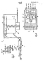
- the first valve chamber 22 has an inlet valve 1 and a vent valve 20, the second valve chamber 7 has an adjustable pressure compensation valve 6. In the zero state, i.e. Without compressed air, the inlet valve 1 and the pressure compensation valve 6 are closed and the vent valve 20 is open.
- Port N of the controller is now connected to the compressed air network.
- the network pressure N is on the one hand at the inlet valve 1 and on the other hand slows down into the inlet pressure chamber 14 via an inlet nozzle 17, builds up there and presses a first control chamber membrane 19 and a second control chamber membrane 16 downward.
- the membranes are mechanically coupled to one another via a support ring 15.
- the vent valve 20 closes and the inlet valve 1 is opened.
- the air flows into the first valve chamber 22, the so-called control chamber, and from there via a connecting line into the second valve chamber 7, the so-called control chamber.
- a control chamber membrane 8 opens the pressure compensation valve 6 and there is pressure compensation between the inlet pressure chamber 14 and the two valve chambers 22, 7, i.e. the membranes 19, 16 go up, the inlet valve 1 is closed and the vent valve 20 is opened, i.e. the pressure in the control chamber decreases to the outside through an outlet AL until the pressure compensation valve 6 is closed again via the pressure regulating spring 9. The inlet valve 1 is now opened again, etc.
- the stabilized pressure A set by means of the rotary knob 40 is taken from the first via the second valve chamber 7.
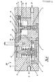
- the low overall height of the pressure regulating unit 30 results, as can already be seen from FIG. 3, but in particular from FIG. 4, from the lateral arrangement of the valve chambers 22 and 7 and the resulting simplified supply and discharge conditions, with the mains pressure supply line P on the side the control chamber 22 and the control pressure lead A on the Side of the control chamber 7 opens. A somewhat linear arrangement of the pressure control units 30 is thus achieved.
- the control diaphragms 16, 19 on the one hand and the control diaphragm 8 on the other hand are arranged next to one another in offset parallel planes. The control chamber membranes 8 are offset against the bottom of the housing and the control chamber membranes 16, 19 against the top of the housing.
- valve chambers 7, 22 are each accessible from the relevant housing sides via valve chamber covers 5 and 10 (FIG. 4).
- This structure allows the housing 41 to be designed as a solid block in which corresponding openings and bores are provided.
- the block is preferably made of aluminum.
- the pressure preselection of the pressure control units 30 takes place by means of a rotary knob 40.
- An axially adjustable clamping screw 11 is provided as the actuator, by means of which the spring preload of the pressure regulating spring 9, which acts on the valve 6 via the membrane 8, can be set.
- the rotary knob sits on an axially immovable shaft 12, which is rotatably mounted in the housing 41 in the area between the two valve chambers.
- the shaft 12 is not arranged coaxially to the clamping screw 11, but is connected to the drive via a pinion with a gear on the clamping screw 11.
- the stroke of the clamping screw 11, which should be as large as possible to achieve a large control range, does not affect the desired, low overall height of the device out.
- the different pressure ranges that may be desired for the two control units 30 can be achieved by appropriate selection of the pressure regulating spring 9.
- the pressure measuring and control device described has the advantage of a small overall height due to the division of each pressure control unit 30 into two functional units lying next to one another.
- the pressure is adjusted via a gear reduction, so that on the one hand the knobs 40 remain axially fixed and thus do not influence the overall height and on the other hand a sensitive adjustment is possible.
- the compact design which combines two parallel pressure control units 30, a pneumatic measuring point switch 31, two safety valves 35, 36 and an electronic pressure measuring unit 37 in one block, results in a small overall size of the device.
Landscapes
- Physics & Mathematics (AREA)
- Fluid Mechanics (AREA)
- General Physics & Mathematics (AREA)
- Engineering & Computer Science (AREA)
- Automation & Control Theory (AREA)
- Control Of Fluid Pressure (AREA)
- Measuring Fluid Pressure (AREA)
- Fluid-Pressure Circuits (AREA)
- Supply Devices, Intensifiers, Converters, And Telemotors (AREA)
Abstract
Description
- Die Erfindung betrifft ein Druckmess- und Regelgerät mit Anschlüssen für einen Netzdruck und mindestens einen einstellbaren Regeldruck, einem Druckmesswerk sowie mindestens einer Druckregeleinheit, welche eine Netzdruckzuleitung und eine Regeldruckableitung, ein hadbetätigbares Stellglied für die Regeldruckeinstellung sowie zwei miteinander zusammenwirkende Ventilkammern aufweist, von denen die erste als Regelkammer ausgebildet und in Abhängigkeit vom Regeldruck mit der Netzdruckzuleitung oder einer Abluftöffnung verbindbar ist und die zweite als Steuerkammer mit dem Stellglied verbunden ist zur Einstellung des Regeldruckes.
- Geräte dieser Art sind bekannt. Sie dienen als Druckgeber für die Entnahme von einstellbaren Referenzdrücken sowie als Druckmessgeräte für gasförmige Medien. Solche Geräte lagen bisher in Form voluminöser Messkoffer oder von Einschüben für Laborsysteme vor, jedoch nicht als Handgeräte im sog. "Multimeterformat" für den mobilen Einsatz.
- Die Abmessungen bekannter Geräte waren vor allem in der Höhe durch die Ausdehnung der Druckregeleinheit bestimmt, deren Ventilkammern zusammen mit dem Stellglied koaxial aufgebaut waren.
- Es stellt sich damit die Aufgabe, ein Druckmess- und Regelgerät der eingangs genannten Art zu schaffen, das als Handgerät mit geringen Abmessungen und insbesondere reduzierter Höhe ausgestaltet ist. Diese Aufgabe wird erfindungsgemäss dadurch gelöst, dass zur Erzielung geringer Bauhöhe die Ventilkammern der Druckregeleinheit seitlich nebeneinander angeordnet sind, wobei die Netzdruckzuleitung regelkammerseitig und die Regeldruckableitung steuerkammerseitig oder regelkammerseitig münden. Damit lassen sich auf kleinem Raum zwei Druckregeleinheiten parallel nebeneinander anordnen und unabhängig voneinander gleichzeitig zwei Referenzdrücke erzeugen, wobei jede Druckregeleinheit über den Messstellenumschalter zur Druckeinstellung und Ueberprüfung separat und ohne Beeinflussung der jeweils anderen Einheit mit dem Druckmesswandler verbunden werden kann. Die zentrale Anordnung des Messstellenumschalters zwischen den beiden Druckregelkreisen und dem Druckmesswandler führt zu einem raumsparenden Aufbau.
- Nachfolgend wir ein Ausführungsbeispiel der Erfindung anhand der beiliegenden Zeichnungen näher beschrieben. Darin zeigen:
- Fig. 1 den schematischen Aufbau des Gerätes;
- Fig. 2 eine Aufsicht auf die Geräteoberseite mit schematisch eingezeichneten Druckkanälen;
- Fig. 3 ein Funktionsschema einer Druckregeleinheit, und
- Fig. 4 einen Schnitt durch die Längsachse der Druckregeleinheit nach Fig. 3.
- Zunächst sei anhand der ersten Figur der grundsätzliche Aufbau des Druckmess- und Regelgerätes beschrieben. Es weist einen Netzdruckanschluss N zur Versorgung des Gerätes mit einem Netzdruck auf,dessen Höhe nicht stabilisiert zu sein braucht, jedoch über den einstellbaren Regeldrücken liegt. Am Netzdruckeingang ist ein erstes Sicherheitsventil 35 angeordnet, dessen Schwellwert einstellbar ist. Der Netzdruckanschluss N ist mit zwei parallel zueinander angeordneten Druckregeleinheiten 30 verbunden, die grundsätzlich gleich aufgebaut sind, jedoch zur Einstellung unterschiedlicher Druckbereiche ausgebildet sein können. Die Druckregeleinheiten 30 gestatten die manuelle Einstellung eines wählbaren Druckes im entsprechenden Druckbereich. Dieser Regeldruck hängt im wesentlichen nur von der gewählten Einstellung der Druckregeleinheit ab, deren Aufbau nachfolgend anhand der Fig. 3 und 4 detailliert erläutert wird. Die Regeldruckableitungen A der Druckregeleinheiten 30 sind einerseits mit einem zentralen Messstellenumschalter 31 und andererseits mit Anschlüssen Al bzw. A2 für die Druckentnahme verbunden. Der Messstellenumschalter 31 verbindet die Regeldruckableitung bzw. zwei Messanschlüsse Ml und M2 wahlweise mit einem Druckmesswerk 37, das einen Druckumsetzer 32 besitzt, dessen Signale in einem Analog-Digitalwandler 33 zu digitalen Werten gewandelt werden und auf der Digitalanzeige 34 erscheinen. Je nach Stellung des Messstellenumschalters 31 wird der an einem der Anschlüsse Al oder A2 herrschende Regeldruck angezeigt, was die exakte manuelle Einstellung jeder der Druckregeleinheiten 30 auf den gewünschten Druckwert gestattet. In einer dritten Stellung des Umschalters 31 ist das Druckmesswerk 37 direkt mit den Messanschlüssen Ml und M2 verbunden. Damit kann einerseits das Druckmesswerk 37 geeicht werden und andererseits können unabhängig von der beschriebenen Druckregelung die Drücke weiterer Druckquellen gemessen werden. Im beschriebenen Druckmesskreis ist ebenfalls ein Sicherheitsventil 36 vorgesehen.
- In Fig. 2 ist der umschriebene Aufbau des Gerätes in schematischer Aufsicht auf eine konkrete Geräteausführung ersichtlich. Das Gerät ist im wesentlichen quaderförmig in der Art bekannter Elektro-Multimeter aufgebaut. Die Anschlüsse N, Al, A2, Ml, M2 liegen nebeneinander an der unteren Schmalseite des Gerätes und sind mittels der schematisch eingezeichneten Kanäle mit den vorerwähnten Bauteilen verbunden. Jede der beiden Druckregeleinheiten 30 besitzt einen Drehknopf 40 als Einstellorgan, die auf der Gehäuseoberseite angeordnet sind. Der obere Geräteteil ist zur Aufnahme des als Einheit ausgebildeten Druckmesswerkes 37 ausgestaltet. Es weist insbesondere eine digitale Anzeige 34, einen Einheitenumschalter 38 zur Aenderung der Ableseempfindlichkeit und einen Funktionsschalter 39 zum Ein- und Ausschalten des Gerätes für die Batterieprüfung etc. auf.
- Das Druckmesswerk 37 ist als Einheit ein-und ausbaubar. Das in Fig. 2 gezeigte Gerät weist eine geringe Bauhöhe auf, entsprechend dem erwähnten Multimeterformat. Diese Bauhöhe ist im wesentlichen durch die Ausgestaltung der Druckregeleinheiten 30 bestimmt, welche nun anhand der Fig. 3 und 3 näher erläutert werden soll. Zunächst wird anhand der Fig. 3 das grundsätzlich vorbekannte Funktionsprinzip kurz erläutert. Es sind im wesentlichen zwei Ventilkammern 7,22 vorgesehen mit insgesamt drei Ventilen 1,20 und 6. Die erste Ventilkammer 22 weist ein Einlassventil 1 und ein Entlüftungsventil 20 auf, die zweite Ventilkammer 7 ein einstellbares Druckausgleichventil 6. Im Nullzustand, d.h. ohne Druckluft, ist das Einlassventil 1 und das Druckausgleichsventil 6 geschlossen und das Entlüftungsventil 20 ist offen.
- Der Anschluss N des Reglers wird nun am Druckluftnetz angeschlossen. Der Netzdruck N liegt einerseits am Einlassventil 1 und gelangt andererseits verlangsamt über eine Einlassdüse 17 in die Eingangsdruckkammer 14, baut sich dort auf und drückt eine erste Regelkammermembrane 19 und eine zweite Regelkammermembrane 16 nach unten. Die Membranen sind über einen Stützring 15 mechanisch miteinander gekoppelt. Dadurch schliesst das Entlüftungsventil 20, und das Einlassventil 1 wird geöffent. Die Luft strömt in die erste Ventilkammer 22, die sog. Regelkammer, und von dort über eine Verbindungsleitung in die zweite Ventilkammer 7, die sog. Steuerkammer. Sobald die mit einer DruckRegulierfeder 9 eingestellte Kraft durch den Gegendruck in der Steuerkammer 7 erreicht ist, öffnet eine Steuerkammermembrane 8 das Druckausgleichsventil 6, und es findet zwischen der Eingangsdruckkammer 14 und den beiden Ventilkammern 22,7 ein Druckausgleich statt, d.h. die Membranen 19,16 gehen nach oben, das Einlassventil 1 wird geschlossen, und das Entlüftungsventil 20 wird geöffnet, d.h. der Druck in der Regelkammer baut sich durch einen Auslass AL solange nach aussen ab, bis das Druckausgleichsventil 6 über die Druckregulierfeder 9 wieder geschlossen ist. Das Eingangsventil 1 wird jetzt wieder geöffnet, usw.
- Der mittels dem Drehknopf 40 eingestellte, stabilisierte Druck A wird der ersten über die zweite Ventilkammer 7 entnommen.
- Die geringe Bauhöhe der Druckregeleinheit 30 ergibt sich, wie schon aus Fig. 3, aber insbesondere aus Fig. 4 ersichtlich ist, aus der seitlichen Anordnung der Ventilkammern 22 und 7 und den dadurch vereinfachten Zuleitungs- und Ableitungsverhältnissen, wobei die Netzdruckzuleitung P auf der Seite der Regelkammer 22 und die Regeldruckableitung A auf der Seite der Steuerkammer 7 mündet. Damit wird eine gewissermassen lineare Anordnung der Druckregeleinheiten 30 erzielt. Um die Länge ebenfalls zu reduzieren, sind die Regelmembranen 16,19 einerseits und die Steuermembrane 8 andererseits in versetzten Parallelebenen nebeneinander angeordnet. Dabei sind die Steuerkammer-Membranen 8 gegen die Gehäuseunterseite und die Regelkammermembranen 16,19 gegen die Gehäuseoberseite hin versetzt. Die entsprechenden Ventilkammern 7, 22 sind je von den betreffenden Gehäuseseiten her über Ventilkammerdeckel 5 bzw. 10 zugänglich (Fig. 4). Dieser Aufbau gestattet es, das Gehäuse 41 als massiven Block auszubilden, in welchem entsprechende Oeffnungen und Bohrungen vorgesehen sind. Vorzugsweise besteht der Block aus Aluminium.
- Die Druckvorwahl der Druckregeleinheiten 30 erfolgt, wie bereits ausgeführt, mittels eines Drehknopfes 40. Als Stellglied ist dabei eine axial verstellbare Spannschraube 11 vorgesehen, mittels welcher die Federvorspannung der Druckregulierfeder 9, welche über die Membran 8 auf das Ventil 6 wirkt, einstellbar ist. Der Drehknopf sitzt auf einer axial unverschieblichen Welle 12, die im Gehäuse 41 im Bereich zwischen den beiden Ventilkammern drehbar gelagert ist. Die Welle 12 ist dabei nicht koaxial zur Spannschraube 11 angeordnet, sondern über ein Ritzel mit einem Zahnrad an der Spannschraube 11 antriebsverbunden. Die damit bewirkte Untersetzung erlaubt ein präzises Feineinstellen jeder Druckregeleinheit 30 und die Anordnundhat den Vorteil, dass der aussenliegende Drehknopf 40 beim Verstellen in seiner Längsachse nicht verschoben wird. Damit wirkt sich der Hub der Spannschraube 11, welcher zur Erzielung eines grossen Regelbereiches möglichst gross ein soll, nicht auf die gewünschte, niedrige Bauhöhe des Gerätes aus. Die für die beiden Regeleinheiten 30 allenfalls gewünschten unterschiedlichen Druckbereiche lassen sich durch entsprechende Wahl der Druckregulierfeder 9 erzielen.
- Das beschriebene Druckmess- und Regelgerät weist den Vorteil geringer Bauhöhe auf durch die Aufteilung jeder Druckregeleinheit 30 in zwei nebeneinanderliegende Funktionseinheiten. Die Druckeinstellung erfolgt über eine Zahnraduntersetzung, so dass einerseits die Drehknöpfe 40 axial fest bleiben und damit die Bauhöhe nicht beeinflussen und andererseits eine feinfühlige Einstellung möglich wird.
- Die kompakte Bauweise, welche zwei parallel liegende Druckregeleinheiten 30, einen pneumatischen Messstellenumschalter 31, zwei Sicherheitsventile 35,36 und ein elektronisches Druckmesswerk 37 in einem Block vereint, ergibt geringe Baumasse des Gerätes.
Claims (10)
Applications Claiming Priority (2)
| Application Number | Priority Date | Filing Date | Title |
|---|---|---|---|
| CH1256/84 | 1984-03-13 | ||
| CH1256/84A CH664224A5 (de) | 1984-03-13 | 1984-03-13 | Druckmess- und regelgeraet. |
Publications (2)
| Publication Number | Publication Date |
|---|---|
| EP0154914A2 true EP0154914A2 (de) | 1985-09-18 |
| EP0154914A3 EP0154914A3 (de) | 1988-12-21 |
Family
ID=4206131
Family Applications (1)
| Application Number | Title | Priority Date | Filing Date |
|---|---|---|---|
| EP85102377A Withdrawn EP0154914A3 (de) | 1984-03-13 | 1985-03-02 | Druckmess- und Regelgerät |
Country Status (6)
| Country | Link |
|---|---|
| US (1) | US4612950A (de) |
| EP (1) | EP0154914A3 (de) |
| JP (1) | JPS60217419A (de) |
| CH (1) | CH664224A5 (de) |
| DE (1) | DE8506317U1 (de) |
| FR (1) | FR2561412B3 (de) |
Cited By (1)
| Publication number | Priority date | Publication date | Assignee | Title |
|---|---|---|---|---|
| DE4343306A1 (de) * | 1993-12-17 | 1995-06-22 | Gastechnic Prod Vertriebges | Verfahren und Vorrichtung zur Regelung des Druckes in einer Gasleitung |
Families Citing this family (6)
| Publication number | Priority date | Publication date | Assignee | Title |
|---|---|---|---|---|
| DE3624720C2 (de) * | 1986-07-22 | 1997-05-28 | Gok Gmbh & Co Kg | Gasdruckregelgerät mit zwei membrangesteuerten Ventileinrichtungen |
| DE4133434C2 (de) * | 1991-10-09 | 1994-12-22 | Gta Gmbh | Verfahren und Meß-Regelstation zur zentralen Überwachung und Steuerung bei der Unterdruckhaltung während der Altlastensanierungsmaßnahmen aus Gebäudeteilen |
| US5327926A (en) * | 1992-12-28 | 1994-07-12 | John A. Blatt | Flow regulator |
| GB2345953B (en) * | 1999-01-22 | 2003-07-23 | Npf Ltd | Electronically controlled pneumatic paintball guns |
| US6568416B2 (en) | 2001-02-28 | 2003-05-27 | Brian L. Andersen | Fluid flow control system, fluid delivery and control system for a fluid delivery line, and method for controlling pressure oscillations within fluid of a fluid delivery line |
| GB2450931A (en) * | 2007-07-13 | 2009-01-14 | Mark Andrew Palmer | Ear-muffs incorporating a pump to control pressure within the ears |
Family Cites Families (7)
| Publication number | Priority date | Publication date | Assignee | Title |
|---|---|---|---|---|
| US2806481A (en) * | 1953-04-08 | 1957-09-17 | Norgren Co C A | Pilot controlled pressure regulator |
| US3115147A (en) * | 1962-02-28 | 1963-12-24 | Robertshaw Controls Co | Pneumatic hesitation relay |
| US3234956A (en) * | 1962-04-19 | 1966-02-15 | Stickle Steam Specialties Co I | Pressure controller with push button set means |
| US3260278A (en) * | 1963-06-14 | 1966-07-12 | Scope Ind Inc | Regulating valve having removable valve unit |
| US3762435A (en) * | 1972-04-12 | 1973-10-02 | J Auwerter | Pressure reducing valve |
| DE2237597A1 (de) * | 1972-07-31 | 1974-02-21 | Gok Gmbh & Co Kg | Gas - umschaltautomatik mit regel und messeinrichtung |
| US4060370A (en) * | 1975-10-02 | 1977-11-29 | Emerson Electric Co. | Manifold gas valve with stepped flow operation |
-
1984
- 1984-03-13 CH CH1256/84A patent/CH664224A5/de not_active IP Right Cessation
-
1985
- 1985-03-02 EP EP85102377A patent/EP0154914A3/de not_active Withdrawn
- 1985-03-05 DE DE8506317U patent/DE8506317U1/de not_active Expired
- 1985-03-12 JP JP60050227A patent/JPS60217419A/ja active Pending
- 1985-03-13 FR FR8503643A patent/FR2561412B3/fr not_active Expired
- 1985-03-13 US US06/711,379 patent/US4612950A/en not_active Expired - Fee Related
Cited By (1)
| Publication number | Priority date | Publication date | Assignee | Title |
|---|---|---|---|---|
| DE4343306A1 (de) * | 1993-12-17 | 1995-06-22 | Gastechnic Prod Vertriebges | Verfahren und Vorrichtung zur Regelung des Druckes in einer Gasleitung |
Also Published As
| Publication number | Publication date |
|---|---|
| DE8506317U1 (de) | 1985-06-13 |
| US4612950A (en) | 1986-09-23 |
| EP0154914A3 (de) | 1988-12-21 |
| JPS60217419A (ja) | 1985-10-31 |
| FR2561412B3 (fr) | 1986-02-28 |
| FR2561412A3 (fr) | 1985-09-20 |
| CH664224A5 (de) | 1988-02-15 |
Similar Documents
| Publication | Publication Date | Title |
|---|---|---|
| DE69116029T2 (de) | Mit Ventilen kombiniertes modulares Steuerpult | |
| DE69606525T2 (de) | Gas druck-regler | |
| DE3637068C2 (de) | ||
| DE102006019997B4 (de) | Saug- und Saugabschalt-Verbundventil | |
| EP0154914A2 (de) | Druckmess- und Regelgerät | |
| DE2042656C3 (de) | ||
| EP0139943B1 (de) | Drosselvorrichtung | |
| DE1428391B2 (de) | Einstellbare Steuervorrichtung für Staubsauger | |
| DE1914672B2 (de) | Druckregelventil | |
| DE3024005A1 (de) | Kraftstoffmengen-messeinrichtung | |
| DE964997C (de) | Regelungsanlage mit einem Umschalter zur wahlweisen selbsttaetigen Regelung oder Handregelung mittels desselben Stellmotors | |
| DE3406942A1 (de) | Drucksensor | |
| DE3907631C2 (de) | Volumenstrom-Kontrollsystem für Schmieranlagen | |
| DE2907218C2 (de) | Gerät zum Mischen zweier Strömungsmedien | |
| DE4106474C2 (de) | Pneumatischer Druckregler mit Pilotsteuerung | |
| DE3812806A1 (de) | Pneumatische filter-regler-anordnung | |
| DE2837692C2 (de) | Gemischbildungseinrichtung | |
| DE3707353C2 (de) | Zwei Ventilanordnungen zur Aufrechterhaltung eines konstanten Druckbereiches in einem Drucksystem | |
| DE3110209C2 (de) | Luftdruckwächter | |
| DE883596C (de) | Schmieroelfilter | |
| DE4211931C1 (en) | Precisely adjustable liq. flow divider - for partial liq. recycle to countercurrent column | |
| DE10234637B4 (de) | Sauganlage für den zahnmedizinischen Einsatz | |
| DE3914278C2 (de) | Druckregler | |
| DE1965489A1 (de) | Mit einem Stroemungsmittel arbeitende Regelvorrichtung | |
| DE1698278C (de) |
Legal Events
| Date | Code | Title | Description |
|---|---|---|---|
| PUAI | Public reference made under article 153(3) epc to a published international application that has entered the european phase |
Free format text: ORIGINAL CODE: 0009012 |
|
| AK | Designated contracting states |
Designated state(s): AT DE FR GB IT |
|
| PUAL | Search report despatched |
Free format text: ORIGINAL CODE: 0009013 |
|
| AK | Designated contracting states |
Kind code of ref document: A3 Designated state(s): AT DE FR GB IT |
|
| RHK1 | Main classification (correction) |
Ipc: G05D 16/20 |
|
| 17P | Request for examination filed |
Effective date: 19890620 |
|
| STAA | Information on the status of an ep patent application or granted ep patent |
Free format text: STATUS: THE APPLICATION IS DEEMED TO BE WITHDRAWN |
|
| 18D | Application deemed to be withdrawn |
Effective date: 19911003 |
|
| RIN1 | Information on inventor provided before grant (corrected) |
Inventor name: SCHMID-WELTI, ERICH |