EP0154955A2 - Maschine zum Anlegen eines Bandes um ein Packgut - Google Patents
Maschine zum Anlegen eines Bandes um ein Packgut Download PDFInfo
- Publication number
- EP0154955A2 EP0154955A2 EP85102706A EP85102706A EP0154955A2 EP 0154955 A2 EP0154955 A2 EP 0154955A2 EP 85102706 A EP85102706 A EP 85102706A EP 85102706 A EP85102706 A EP 85102706A EP 0154955 A2 EP0154955 A2 EP 0154955A2
- Authority
- EP
- European Patent Office
- Prior art keywords
- belt
- band
- drive
- clutch
- electromagnetic clutch
- Prior art date
- Legal status (The legal status is an assumption and is not a legal conclusion. Google has not performed a legal analysis and makes no representation as to the accuracy of the status listed.)
- Granted
Links
Images


Classifications
-
- B—PERFORMING OPERATIONS; TRANSPORTING
- B65—CONVEYING; PACKING; STORING; HANDLING THIN OR FILAMENTARY MATERIAL
- B65B—MACHINES, APPARATUS OR DEVICES FOR, OR METHODS OF, PACKAGING ARTICLES OR MATERIALS; UNPACKING
- B65B13/00—Bundling articles
- B65B13/02—Applying and securing binding material around articles or groups of articles, e.g. using strings, wires, strips, bands or tapes
-
- B—PERFORMING OPERATIONS; TRANSPORTING
- B65—CONVEYING; PACKING; STORING; HANDLING THIN OR FILAMENTARY MATERIAL
- B65B—MACHINES, APPARATUS OR DEVICES FOR, OR METHODS OF, PACKAGING ARTICLES OR MATERIALS; UNPACKING
- B65B13/00—Bundling articles
- B65B13/18—Details of, or auxiliary devices used in, bundling machines or bundling tools
- B65B13/22—Means for controlling tension of binding means
Definitions
- the invention relates to a machine for applying a band around a packaged product, which is held together after being wrapped by the band after tensioning the band and after connecting the ends of the band, wherein in the drive of the machine an adjustable clutch for dosing the transmissible torque arranged on the packaged belt tension, which is between the motor of the drive and a sliding device for the belt.
- the tape is placed and stretched largely automatically around the packaged goods, whereupon the tape ends are connected and separated from the supply roll.
- the known machines are provided with a tape guide in the form of a yoke or a ring, in the interior of which the packaged goods are placed.
- the end of the belt transported by the drive of the machine into the belt guide is inserted manually or automatically into a connecting station located at the foot of the belt guide.
- the belt is tensioned by the drive arranged in the machine, whereupon after the desired belt tension has been reached, the band ends are connected and the band is cut off from the supply roll.
- Both the transport of the tape through the tape guide and the tensioning of the tape after inserting its end and after holding it in the connection station are carried out by the same drive, however, because of the opposite nature of these two tape movements, i.e.
- the drive can be reversible.
- the reversibility is achieved either by changing the direction of rotation on the drive motor or by a reversing path arranged in the drive path of the drive.
- the invention relates to a drive with a reversing path.
- shift clutches preferably electromagnetic shift clutches, are used, which are shifted alternately.
- a sliding device moving the belt device in the sense of looping around the packaged goods and in the other switching position the band already wrapping around the packaged goods is moved by an opposite movement of the belt pushing device in the sense of tensioning the belt.
- the invention is based on the object of designing a machine of the type described at the outset in such a way that even very small belt tensions can be adhered to exactly, so that even delicate packaged goods can be reliably covered with a belt.
- the clutch is a controllable electromagnetic clutch, in which an armature is under the action of a magnetic restoring force that supports the release of the clutch.
- the machine shown in FIG. 1 for applying a band around a packaged product has a base 1 and a yoke 2 placed thereon.
- the base 1 has in its interior a band-slide device 3 for the band 4, which is shown in simplified form.
- the tape 4 is unwound from a supply roll 5, guided around a deflection roll 6 and then fed to the tape sliding device 3.
- the belt pushing device 3 pushes the belt 4 in guides (not shown) through the yoke 2 and thereby forms a loop, the end of which is inserted into a connection station 7 and held there.
- the connection station 7 lies on one the base 1 formed work surface 8 through which a packaged item 9 to be enclosed with the band 4 is placed.
- the belt pushing device 3 is moved in the opposite direction, whereby the belt 4 emerges from the yoke 2 and tightens and wraps around the packaged goods 9 until it has reached the set belt tension.
- the connecting station 7 then takes over the connection of the tape ends and the separation of the tape 4.
- the type of tape used and the type of connection are not essential in connection with the present invention. However, it should be possible to use very thin tapes, cords or wires with the machine according to FIG. 1, for which a low tape tension may also be permissible.
- the band ends can be connected in various ways, for example by means of a connecting sleeve, by deforming the band ends or by welding the band ends in the case of plastic bands.
- the shape of the band 4 can also vary widely and can be narrow or wide or also have the shape of a cord or a wire.
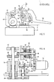
- the drive shown in FIG. 2 is a drive with a reversing path, which is designated by 10 in FIG. 2.
- a motor 11 e.g. an electric, hydraulic or pneumatic motor, drives via an enveloping drive 12, which consists of wheels 13, 14 and an enveloping member 15 and e.g. a toothed belt drive can be a main shaft 16.
- the main shaft 16 is rotatably mounted by means of roller bearings 17, 18 in a wall 19 of a housing (not shown) accommodated in the base 1 and in a further housing part 20.
- a pinion 21 of the belt sliding device 3 is loosely mounted on the main shaft 16 and by means of an enveloping member 22, preferably a toothed belt, coupled to a wheel 23.
- the belt drive consisting of the pinion 21, the sleeve member 22 and the wheel 23 forms the belt sliding device 3 for the belt 4, as will be explained more clearly with reference to FIG. 3.
- the pinion 21 can be coupled to the main shaft 16 with the aid of an electromagnetic clutch 24.
- the clutch 24 consists of an electrical winding 25 fastened to the wall 19, a magnet housing 26 connected to the main shaft 16 and an armature disk 27 which is connected to the pinion 21 in a manner not shown, but which extends along the main shaft 16 in the direction of Magnet housing 26 can move.
- Fig. 2 the individual parts of the drive are pulled apart for a better overview. Accordingly, the distances between the parts of the electromagnetic clutch 24 are greatly increased.
- the electromagnetic clutch 24 is switched by energizing the winding 25, as a result of which the armature disk 27 lies firmly against the magnet housing 26 rotating with the main shaft 16 and thereby sets the pinion 21 in rotation.
- a further electromagnetic clutch 28 is arranged, which has a winding 29 fastened to the wall 19, a magnet housing 30 connected to the main shaft 16 and an armature disk 31.
- the armature disk 31 is, in a departure from the design of the magnetic coupling 24, non-rotatably, but displaceably mounted on a drive wheel 32 provided with teeth.
- the driving wheel 32 together with a driving hub 33, is freely rotatably mounted on the main shaft 16. If the electromagnetic clutch 28 is switched, the armature disk 31 is held on the magnet housing 30 and rotates together with the latter.
- the driving hub 33 connected to the driving wheel 32 and a pinion 34 attached to it rotates.
- the pinion 34 forms, together with a wheel 35 and an enveloping member 36, an enveloping drive for driving a control shaft 37 mounted in roller bearings 44 a pinion 38 and a perforated or toothed disk 39 are attached, to which a measuring device, for example a photocell 40, is directed, which generates a control pulse under certain operating conditions.
- a measuring device for example a photocell 40
- the pinion 38 meshes with a gear 42 fastened on a shaft 41, the wheel 23 of the belt-sliding device 3 being fastened to the other end of the shaft 41.
- the shaft 41 is rotatably supported in roller bearings 43.
- FIG. 3 the belt sliding device is shown in more detail.
- the reference numerals in FIGS. 3 and 4 which are also used in FIG. 2, denote the same parts and are only explained to the extent that this is necessary.
- the band 4 moves to wrap the packaged goods in Fig. 3 from bottom to top and vice versa when tensioning the band 4.
- the band 4 runs on the outer surface of the envelope member 22 and is by an adjustable eccentric 43 on the envelope member 22, which here Timing belt is pressed.
- the eccentric disc 43 By means of the eccentric disc 43, the length of the tape for taking the tape 4 through the enveloping body 22 is additionally lengthened and at the same time the tape 4 is pressed onto the enveloping body 22. In this way, a sufficient tensile force can be exerted on the belt 4 to generate the belt tension.
- the enveloping drive 34, 35, 36 of the reversing path 10 and the additional gear 38, 42 are also shown in broken lines.
- FIG. 4 shows the essential parts of the drive of the machine with the two electromagnetic clutches 24, 28.
- the wall 19 is designed in such a way that both the shaft 41 and the control shaft 37, see FIG. 3, are mounted therein.
- the windings 25, 29 of the two electromagnetic clutches 24, 28 are fastened to the wall 19 by means of a housing, while the magnet housings 26, 30 form an annular channel in which the winding 25, 29 is immersed.
- the surface of the magnet housing 26, 30 which cooperates with the armature disk 27, 31 is provided with a friction lining 45.
- the electromagnetic clutch 28 is designed not only to transmit a torque, but also to limit this torque.
- the magnitude of the torque can be achieved by adjusting the winding voltage.
- the transmitted torque is also dependent on the restoring force with which the armature 31 is pulled against the driving wheel when uncoupling. It has now surprisingly been found that a much more precise setting of the transmitted torque is achieved if the restoring force is applied magnetically.
- permanent magnets 47 are inserted in the flange 46 of the driving hub 33, the number and shape of which can be selected as required. Four to eight flat cylindrical permanent magnets 47 are expediently used.
- permanent magnets 47 can be used not only in a machine according to FIG. 1, but also in an apparatus operated by hand according to FIGS. 5 and 6.
- the apparatus shown schematically in FIG. 5 is provided with a base plate 50 on which the moving parts of the apparatus are supported.
- the base plate 50 is placed on the packaged goods 9 to be outlined and the band 4 is manually pulled around the packaged goods and inserted into the apparatus.
- a plastic band is provided as band 4, which is welded by a welding jaw 51 when it is pressed against the base plate 50 and moved back and forth in the direction of the arrow.
- the movement of the welding jaw 51 takes place by means of a fork lever 53 moved by an eccentric 52.
- the welding jaw 51 is pressed against the base plate 50 by the force of a spring via a lever 56 pivotably mounted in an axis 55 when a pawl 57 from the position shown in FIG. 5 shown position is pivoted.
- a lever 58 By lifting a lever 58, the lever 56 and thus the fork lever 53 with the welding jaw 51 can be raised by a roller 59 acting on the lever 56.
- a rocker which can be pivoted about an axis 61 is simultaneously pivoted against the force of a spring 63.
- a gap is formed between the rocker 62 and a tensioning wheel 64, whereby the band 4 is released.
- the tensioning wheel 64 serves to maintain the tensioning force suitable for the band until the welding is finished.
- another wear device for the band 4 can also be used. What is essential is the drive of the tensioning wheel 64, which enables the belt 4 to be precisely maintained at a specific tensioning force.
- FIG. 6 shows wall parts 65, 66, 67 of the housing of the apparatus according to FIG. 5, which form bearing parts for the drive with housing parts 68, 69, 70, 71.
- an electric motor 72 is supported, one Main shaft 73 drives.
- a pinion 74 of an enveloping drive 75 is fastened, the enveloping member of which surrounds, for example, a toothed belt, the pinion 74 and a wheel 77, which is freely rotating on a shaft 48 mounted in the wall part 65 and in the housing part 69.
- An armature slide 79 is mounted on the wheel 77 in a rotationally fixed but displaceable manner.
- the armature disk 79 is part of the electromagnetic clutch 28, which is suitable not only for transmitting a torque, but also for limiting this torque, as shown in FIGS. 2 and 4 for the strapping machine according to FIG. 1.
- an electrical winding 80 is fastened to the housing part 69 and surrounded by a magnet housing 81 which is fixedly connected to the shaft 78.
- the winding 80 is excited, the armature disk 21 is pulled firmly onto the magnet housing 81, as a result of which the wheel 77 of the enveloping drive 75 sets the shaft 78 in rotation via the magnet housing 81.
- This rotation is transmitted via a bevel gear 82, 83 to the tensioning wheel shaft 84 and thereby the tensioning wheel 64 is driven in the sense of tensioning the belt 4.
- the peripheral force acting on the tensioning wheel 64 is set to a value which is below the tearing tension of the band 4.
- the magnetic coupling 28 is switched off by a measuring device, e.g. a photocell 40, which generates a control pulse for switching off the clutch 28 when the speed of the magnet housing 81 changes.
- eccentric shaft 52 for moving the fork lever 53 and the welding jaw 51 is driven by the main shaft 73 via an angular gear 85, 86.
- the enveloping drive 75 can also be replaced by a gear transmission.
- a further improvement in the setting accuracy of the torque of the electromagnetic clutch 28 is achieved in that the nearby parts, i.e. the wall 19 and the driving wheel 33 in FIGS. 2 and 4 or the wall part 69 and the wheel 77 in FIG. 6 are made of paramagnetic or electrically insulating material. This largely avoids residual phenomena.
- the electromagnetic clutch 28 is switched off, the magnetic field is reduced with a delay.
- the residual magnetism is small because of the parts made of paramagnetic or insulating material and is easily overcome by the force of the permanent magnets 47, so that the electromagnetic clutch 28 is reproducibly switched off with the set torque.
- the area of application of the machine is considerably expanded by relatively simple means. If the set belt tension is reached when the belt 4 is tensioned, the clutch 28 begins to slip, as a result of which the perforated or toothed disk 39 in FIGS. 2 and 4 or the magnet housing 81 runs more slowly. The photocell 40 thereby detects a change in the pulses, which is a signal for switching off the clutch 28 or for switching off the motor 11 in FIG. 2 or 72 in FIG. 6.
Landscapes
- Engineering & Computer Science (AREA)
- Mechanical Engineering (AREA)
- Basic Packing Technique (AREA)
- Preliminary Treatment Of Fibers (AREA)
Abstract
Description
- Die Erfindung betrifft eine Maschine zum Anlegen eines Bandes um ein Packgut, das nach dem Umschlingen durch das Band nach dem Spannen des Bandes sowie nach dem Verbinden der Bandenden zusammengehalten ist, wobei in dem Antrieb der Maschine eine in ihrem übertragbaren Drehmoment einstellbare Kupplung zur Dossierung der auf das Packgut auszuübenden Bandspannung angeordnet ist, die zwischen dem Motor des Antriebes und einer Schiebevorrichtung für das Band liegt.
- Zum Anlegen eines Bandes oder mehrerer Bänder, mit dem bzw. denen ein offenes oder verpacktes Gut zusammengehalten wird, sind verschiedene Vorrichtungen und Maschinen bekannt. Solche Vorrichtungen dienen dazu, das um das Gut gelegte Band zu spannen, an den Bandenden zu verbinden und von der Vorratsrolle zu trennen. Die hierzu verwendeten Vorrichtungen werden entweder manuell betätigt oder werden mit einem hydraulischen, pneumatischen oder elektrischen Antrieb ausgerüstet. Das Anlegen des Bandes um das zu umschlingende Gut und das Einführen des Bandes mit der erforderlichen Ueberlappung der Bandenden in die Vorrichtung wird hierbei manuell ausgeführt; nur der eigentliche Verbindungsvorgang mit vorherigem Spannen des Bandes erfolgt durch die Vorrichtung.
- Bei den bekannten Maschinen wird das Band weitgehend selbsttätig um das Packgut gelegt und gespannt, worauf die Bandenden verbunden und von der Vorratsrolle getrennt werden.
- Damit das Anlegen des Bandes selbsttätig erfolgen kann, sind die bekannten Maschinen mit einer Bandführung in Form eines Joches oder eines Ringes versehen, in dessen Innenraum das Packgut gelegt wird. Das Ende des vom Antrieb der Maschine in die Bandführung transportierten Bandes wird in eine am Fuss der Bandführung angeordnete Verbindungsstation von Hand oder auch selbsttätig eingeführt. Nun wird durch den in der Maschine angeordneten Antrieb das Band gespannt, worauf nach Erreichen der gewünschten Bandspannung das Verbinden der Bandenden und das Abschneiden des Bandes von der Vorratsrolle durchgeführt wird. Sowohl der Transport des Bandes durch die Bandführung als auch das Spannen des Bandes nach dem Einführen seines Endes und nach dem Festhalten in der Verbindungsstation werden durch denselben Antrieb durchgeführt, jedoch muss wegen der Gegenläufigkeit dieser beiden Bandbewegungen, d.h. des Umschlingens des Packgutes einerseits und Spannen des Bandes andererseits, der Antrieb reversierbar sein. Die Reversierbarkeit wird entweder durch Drehrichtungsänderung am Antriebsmotor oder durch einen im Antriebspfad des Antriebes angeordneten Reversierpfad erreicht.
- Die Erfindung betrifft einen Antrieb mit Reversierpfad. Damit jeweils die richtige Bandbewegung erreicht wird, werden Schaltkupplungen, vorzugsweise elektromagnetische Schaltkupplungen, eingesetzt, die wechselweise geschaltet werden. In der einen Schaltstellung dieser Kupplungen wird eine das Band bewegende Schiebevorrichtung im Sinne des Umschlingens des Packgutes und in der andern Schaltstellung das das Packgut bereits umschlingende Band durch eine entgegengesetzte Bewegung der Bandschiebevorrichtung im Sinne des Spannens des Bandes bewegt.
- Da zum Spannen von Packgut verschiedene Bänder vewendet werden, ist es erforderlich, die Bandspannung einerseits auf das Band und andererseits auf das Packgut abzustimmen. Aus diesem Grunde ist es naheliegend, die beim Spannen des Bandes eingeschaltete Kupplung gleichzeitig auch als eine das zu übertragende Drehmoment zu begrenzen bestimmte Schaltkupplung auszubilden. Dies kann bei elektromagnetischen Kupplungen durch Regelung der Erregerspannung erreicht werden, doch lässt die Genauigkeit der hierbei erreichten Einstellung des Uebertragungsmomentes vor allem bei kleinen Uebertragungsmomenten sehr zu wünschen übrig. Dadurch ist die Verwendung ganz dünner Bänder mit niederer zulässiger Bandspannung oder das Verpacken von zerbrechlichem oder unstabilem Packgut praktisch ausgeschlossen.
- Hier setzt die Erfindung ein, der die Aufgabe zugrundeliegt, eine Maschine der eingangs beschriebenen Art so auszugestalten, dass auch sehr kleine Bandspannungen exakt eingehalten werden können, so dass auch heikles Packgut zuverlässig mit einem Band umspannt werden kann. Diese Aufgabe wird gemäss der Erfindung dadurch gelöst, dass die Kupplung eine steuerbare elektromagnetische Kupplung ist, bei der ein Anker unter der Wirkung einer das Lösen der Kupplung unterstützende magnetischen Rückstellkraft steht.
- Die Erfindung ist in der Zeichnung in zwei Ausführungsbeispielen dargestellt und nachfolgend beschrieben. Es zeigen:
- Fig. 1 eine Maschine zum Anlegen eines Bandes um ein Packgut, teilweise geschnitten,
- Fig. 2 eine schematische Darstellung des Antriebes für eine Maschine nach Fig. 1,
- Fig. 3 eine-Seitenansicht eines Teils des Antriebs der Maschine aus Richtung III in Fig. 2,
- Fig. 4 einen Schnitt längs der Linie IV - IV in Fig. 3.
- Fig. 5 eine schematisch dargestellte Seitenansicht eines Apparates zum Anlagen eines Bandes um ein Packgut, und
- Fig. 6 eine schematische Darstellung des Antriebes für den Apparate nach Fig. 5.
- Die in Fig. 1 dargestellte Maschine zum Anlegen eines Bandes um ein Packgut weist einen Sockel 1 und ein darauf aufgesetztes Joch 2 auf. Der Sockel 1 weist in seinem Innenraum eine vereinfacht dargestellte Bandschiebevorrichtung 3 für das Band 4 auf. Das Band 4 wird von einer Vorratsrolle 5 abgewickelt, um eine Umlenkrolle 6 geführt und anschliessend der Bandschiebevorrichtung 3 zugeführt. Die Bandschiebevorrichtung 3 schiebt das Band 4 in Führungen (nicht dargestellt) durch das Joch 2 und bildet hierbei eine Schlinge, deren Ende in eine Verbindungsstation 7 eingelegt und dort festgehalten wird. Die Verbindungsstation 7 liegt auf einer, durch den Sockel 1 gebildeten Arbeitsfläche 8, durch die ein mit dem Band 4 zu umschliessendes Packgut 9 gelegt wird. Nun wird die Bandschiebevorrichtung 3 in umgekehrter Richtung bewegt, wodurch das Band 4 aus dem Joch 2 austritt und sich enger und enger um das Packgut 9 legt, bis es die eingestellte Bandspannung erreicht hat. Die Verbindungsstation 7 übernimmt hierauf das Verbinden der Bandenden und das Abtrennen des Bandes 4. Die Art des verwendeten Bandes und die Art der Verbindung sind im Zusammenhang mit der vorliegenden Erfindung nicht wesentlich. Es sollen mit der Maschine nach Fig. 1 jedoch sehr dünne Bänder, Schnüre oder Drähte verwendet werden könen, für die auch eine geringe Bandspannung zulässig sein kann. Das Verbinden der Bandenden kann auf verschiedene Art und Weise erfolgen, z.B. durch eine Verbindungshülse, durch Verformen der Bandenden oder durch Schweissen der Bandenden bei Kunststoffbändern. Die Form des Bandes 4 kann ebenfalls stark variieren und kann schmal oder breit sein oder auch die Form einer Schnur oder eines Drahtes aufweisen.
- Der in Fig. 2 dargestellte Antrieb ist, wie bereits erwähnt wurde, ein Antrieb mit einem Reversierpfad, der in Fig. 2 mit 10 bezeichnet ist.
- Ein Motor 11, z.B. ein Elektro-, Hydro- oder Pneumatik-Motor, treibt über einen Hülltrieb 12, der aus Rädern 13, 14 und einem Hüllglied 15 besteht und z.B. ein Zahnriementrieb sein kann, eine Hauptwelle 16 an. Die Hauptwelle 16 ist mittels Wälzlägern 17, 18 in einer Wand 19 eines im Sockel 1 untergebrachten Gehäuses (nicht dargestellt) und in einem weiteren Gehäuseteil 20 drehbar gelagert.
- Auf der Hauptwelle 16 ist ein Ritzel 21 der Bandschiebevorrichtung 3 lose gelagert und mittels eines Hüllgliedes 22, vorzugsweise eines Zahnriemens, mit einem Rad 23 gekuppelt. Der aus dem Ritzel 21, dem Hüllglied 22 und dem Rad 23 bestehende Hülltrieb bildet die Bandschiebevorrichtung 3 für das Band 4, wie dies noch anschaulicher anhand von Fig. 3 erläutert wird. Das Ritzel 21 kann mit Hilfe einer elektromagnetischen Kupplung 24 mit der Hauptwelle 16 gekuppelt werden. Die Kupplung 24 besteht aus einer an der Wand 19 befestigten elektrischen Wicklung 25, einem mit der Hauptwelle 16 verbundenen Magnetgehäuse 26 und aus einer Ankerscheibe 27, die in nicht dargestellter Weise mit dem Ritzel 21 verbunden ist, sich jedoch längs der Hauptwelle 16 in Richtung des Magnetgehäuses 26 bewegen kann.
- In Fig. 2 sind die einzelnen Teile des Antriebes zur besseren Uebersicht auseinandergezogen. Dementsprechend sind auch die Abstände zwischen den Teilen der elektromagnetischen Kupplung 24 stark vergrössert. Die Schaltung der elektromagnetischen Kupplung 24 erfolgt durch Erregung der Wicklung 25, wodurch die Ankerscheibe 27 sich fest an das mit der Hauptwelle 16 rotierende Magnetgehäuse 26 anlegt und dadurch das Ritzel 21 in Drehung versetzt.
- Auf der der elektromagnetischen Kupplung 24 entgegengesetzten Seite der Wand 19 ist eine weitere elektromagnetische Kupplung 28 angeordnet, die eine an der Wand 19 befestigte Wicklung 29, ein mit der Hauptwelle 16 verbundenes Magnetgehäuse 30 und eine Ankerscheibe 31 aufweist. Die Ankerscheibe 31 ist in Abweichung von der Ausführung der Magnetkupplung 24 auf einem mit einer Verzahnung versehenen Mitnehmerrad 32 drehfest, jedoch verschiebbar gelagert. Das Mitnehmerrad 32 ist zusammen mit einer Mitnehmernabe 33 auf der Hauptwelle 16 frei drehbar gelagert. Wird die elektromagnetische Schaltkupplung 28 geschaltet, wird die Ankerscheibe 31 am Magnetgehäuse 30 festgehalten und rotiert zusammen mit diesem. Hierbei dreht auch die mit dem Mitnehmerrad 32 verbundene Mitnehmernabe 33 und dazu ein daran befestigtes Ritzel 34. Das Ritzel 34 bildet zusammen mit einem Rad 35 und einem Hüllglied 36 einen Hülltrieb für den Antrieb einer in Wälzlagern 44 gelagerten Kontrollwelle 37. Auf der Kontrollwelle 37 ist ein Ritzel 38 und eine Loch- oder Zahnscheibe 39 befestigt, auf die eine Messeinrichtung, z.B. eine Photozelle 40 gerichtet ist, die bei bestimmten Betriebsbedingungen einen Steuerimpuls erzeugt.
- Das Ritzel 38 kämmt mit einem auf einer Welle 41 befestigten Zahnrad 42, wobei an dem anderen Ende der Welle 41 das Rad 23 der Bandschiebevorrichtung 3 befestigt ist. Die Welle 41 ist in Wälzlagern 43 drehbar gelagert.
- In Fig. 3 ist die Bandschiebevorrichtung genauer dargestellt. Die Bezugszahlen in Fig. 3 und 4, die auch in Fig. 2 verwendet sind, kennzeichnen gleiche Teile und werden nur, soweit dies erforderlich ist, erläutert. Das Band 4 bewegt sich zum Umschlingen des Packgutes in Fig. 3 von unten nach oben und umgekehrt beim Spannen des Bandes 4. Das Band 4 läuft auf der Aussenfläche des Hüllgliedes 22 und wird durch eine einstellbare Exzenterscheibe 43 auf das Hüllglied 22, das hier ein Zahnriemen ist, gepresst. Durch die Exzenterscheibe 43 wird die Bandlänge für die Mitnahme des Bandes 4 durch den Hüllkörper 22 zusätzlich verlängert und gleichzeitig das Band 4 auf den Hüllkörper 22 gepresst. Auf diese Weise kann auf das Band 4 eine ausreichende Zugkraft zur Erzeugung der Bandspannung ausgeübt werden. In Fig. 3 ist weiter der Hülltrieb 34, 35, 36 des Reversierpfades 10 und das Vorgelege 38, 42 gestrichelt eingezeichent.
- In Fig. 4 sind die wesentlichen Teile des Antriebes der Maschine mit den beiden elektromagnetischen Kupplungen 24, 28 dargestellt. Die Wand 19 ist in der Weise ausgebildet, dass sowohl die Welle 41 als auch die Kontrollwelle 37, siehe Fig. 3, darin gelagert sind.
- Die Wicklungen 25, 29 der beiden Elektromagnetkupplungen 24, 28 sind mittels eines Gehäuses an der Wand 19 befestigt, während die Magnetgehäuse 26, 30 einen Ringkanal bilden, in dem die Wicklung 25, 29 eintaucht. Die mit der Ankerscheibe 27, 31 zusammenwirkende Fläche des Magnetgehäuses 26, 30 ist mit einem Reibbelag 45 versehen.
- Die elektromagnetische Kupplung 28 ist nicht nur zur Uebertragung eines Drehmomentes, sondern auch zur Begrenzung dieses Drehmomentes ausgelegt. Die Grösse des Drehmoments kann durch Einstellen der Wicklungsspannung erreicht werden. Andererseits ist das übertragene Drehmoment auch von der Rückstellkraft abhängig, mit der die Anker 31 beim Entkuppeln gegen das Mitnehmerrad gezogen wird. Es wurde nun überraschend festgestellt, dass eine wesentlich exaktere Einstellung des übertragenen Drehmomentes erreicht wird, wenn die Rückstellkraft magnetisch aufgebracht wird. Zu diesem Zweck sind in dem Flansch 46 der Mitnehmernabe 33 Permanentmagnete 47 eingesetzt, deren Zahl und Form je nach Bedarf gewählt werden kann. Zweckmässig werden vier bis acht flache zylinderförmige Permanentmagnete 47 verwendet.
- Die Verwendung von Permanentmagneten 47 kann nicht nur bei einer Maschine nach Fig. 1 angewandt werden, sondern auch bei einem von Hand bedienten Apparat gemäss Fig. 5 und 6.
- Der in Fig. 5 schematisch dargestellte Apparat ist mit einer Grundplatte 50 versehen, auf der die beweglichen Teile des Apparates abgestützt sind. Die Grundplatte 50 wird auf das zu umreissende Packgut 9 gestellt und das Band 4 manuell um das Packgut gezogen und in den Apparat eingelegt. Als Band 4 ist in Fig. 5 ein Kunststoffband vorgesehen, das durch eine Schweissbacke 51 verschweisst wird, wenn sie gegen die Grundplatte 50 gedrückt und gemäss Pfeilrichtung hin und her bewegt wird. Die Bewegung der Schweissbacke 51 erfolgt durch einen von einem Exzenter 52 bewegten Gabelhebel 53. Die Schweissbacke 51 wird durch die Kraft einer Feder über einen in einer Achse 55 schwenkbar gelagerten Hebel 56 gegen die Grundplatte 50 gedrückt, wenn eine Klinke 57 aus der in Fig. 5 dargestellten Lage ausgeschwenkt wird. Durch Anheben eines Hebels 58 kann der Hebel 56 und damit der Gabelhebel 53 mit der Schweissbacke 51 angehoben werden, indem eine Rolle 59 am Hebel 56 angreift.
- Durch das Anheben des um eine Achse 60 schwenkbaren Hebels wird gleichzeitig eine um eine Achse 61 schwenkbare Wippe gegen die Kraft einer Feder 63 geschwenkt. Hierdurch wird ein Spalt zwischen der Wippe 62 und einem Spannrad 64 gebildet, wodurch das Band 4 freigegeben wird. Das Spannrad 64 dient dazu, die für das Band geeignete Spannkraft einzuhalten, bis die Verschweissung beendet ist. Anstelle der Schweissbacke 51 kann auch eine andere Verschleisseinrichtung für das Band 4 verwendet werden. Wesentlich ist der Antrieb des Spannrades 64, der die exakte Einhaltung einer bestimmten Spannkraft für das Band 4 ermöglicht.
- In Fig. 6 sind Wandteile 65, 66, 67 des Gehäuses des Apparates nach Fig. 5 dargestellt, die mit Gehäuseteilen 68, 69, 70, 71 Lagerpartien für den Antrieb bilden. An dem Wandteil 65 ist ein Elektromotor 72 abgestützt, der eine Hauptwelle 73 antreibt. Auf der Hauptwelle 73 ist ein Ritzel 74 eines Hülltriebes 75 befestigt, dessen Hüllglied z.B. ein Zahnriemen, das Ritzel 74 und ein Rad 77 umgibt, das frei drehend auf einer im Wandteil 65 und im Gehäuseteil 69 gelagerten Welle 48 gelagert ist. An dem Rad 77 ist eine Ankerschiebe 79 drehfest, jedoch verschiebbar gelagert. Die Ankerscheibe 79 ist ein Teil der elektromagnetischen Schaltkupplung 28, die nicht nur zur Uebertragung eines Drehmomentes, sondern auch zur Begrenzung dieses Drehmomentes geeignet ist, wie dies in Fig. 2 und 4 für die Umreifungsmaschine nach Fig. 1 dargestellt ist.
- In Fig. 6 ist eine elektrische Wicklung 80 an dem Gehäuseteil 69 befestigt und von einem fest mit der Welle 78 verbundenen Magnetgehäuse 81 umgeben. Bei Erregen der Wicklung 80 wird die Ankerscheibe 21 fest auf das Magnetgehäuse 81 gezogen, wodurch das Rad 77 des Hülltriebes 75 über das Magnetgehäuse 81 die Welle 78 in Drehung versetzt. Diese Drehung wird über ein Kegelradgetriebe 82, 83 auf die Spannradwelle 84 übertragen und dadurch das Spannrad 64 im Sinne eines Spannens des Bandes 4 angetrieben. Durch die elektrische Kupplung 28 wird die am Spannrad 64 wirkende Umfangskraft auf einen Wert eingestellt, der unterhalb der Zerreissspannung des Bandes 4 liegt. Die Möglichkeit einer exakteren Einteilung des übertragenen Drehmomentes wird auch hier durch die Permanentmagnete 47 wie bei der elektromagnetischen Kupplung 28 in Fig. 4 erreicht, die ankerscheibenseitig in dem Rad 77 eingesetzt sind. Das Abschalten der Magnetkupplung 28 erfolgt wie bei der Ausführung nach Fig. 2 durch eine Messeinrichtung, z.B. eine Photozelle 40, die bei Aenderung der Drehzahl des Magnetgehäuses 81 einen Steuerimpuls zum Abschalten der Kupplung 28 erzeugt.
- Der Vollständigkeit halber sei noch erwähnt, dass die Exzenterwelle 52 zum Bewegen des Gabelhebels 53 und der Schweissbacke 51 von der Hauptwelle 73 über ein Winkelgetriebe 85, 86 angetrieben wird. Im weitern kann auch der Hülltrieb 75 durch ein Zahnradgetriebe ersetzt werden.
- Eine weitere Verbesserung der Einstellgenauigkeit des Drehmomentes der elektromagnetischen Kupplung 28 wird dadurch erreicht, dass die in der Nähe liegenden Teile, d.h. die Wand 19 und das Mitnehmerrad 33 in Fig. 2 und 4 bzw. der Wandteil 69 und das Rad 77 in Fig. 6, aus paramagnetischem oder elektrisch isolierendem Material ausgeführt werden. Dadurch werden Remanenzerscheinungen weitgehend vermieden. Beim Abschalten der elektromagnetischen Kupplung 28 wird das magnetische Feld mit Verzögerung abgebaut. Der Restmagnetismus ist jedoch wegen der verwendeten Teile aus paramagnetischem oder isolierendem Material klein und wird problemlos durch die Kraft der Permanentmagnete 47 überwunden, so dass die Abschaltung der Elektromagnetischen Kupplung 28 reproduzierbar mit dem eingestellten Drehmoment erfolgt.
- Durch die beschriebenen Mittel wird der Anwendungsbereich der Maschine durch verhältnismässig einfache Mittel wesentlich erweitert. Wird beim Spannen des Bandes 4 die eingestellte Bandspannung erreicht, beginnt die Kupplung 28 zu rutschen, wodurch die Loch- oder Zahnscheibe 39 in Fig. 2 und 4 bzw. das Magnetgehäuse 81 langsamer läuft. Die Photozelle 40 stellt dadurch eine Aenderung der Impulse fest, was ein Signal für das Abschalten der Kupplung 28 oder für das Ausschalten des Motors 11 in Fig. 2 bzw. 72 in Fig. 6 darstellt.
Claims (7)
Applications Claiming Priority (2)
| Application Number | Priority Date | Filing Date | Title |
|---|---|---|---|
| CH1247/84A CH662791A5 (de) | 1984-03-13 | 1984-03-13 | Maschine zum anlegen eines bandes um ein packgut. |
| CH1247/84 | 1984-03-13 |
Publications (3)
| Publication Number | Publication Date |
|---|---|
| EP0154955A2 true EP0154955A2 (de) | 1985-09-18 |
| EP0154955A3 EP0154955A3 (en) | 1988-06-29 |
| EP0154955B1 EP0154955B1 (de) | 1991-01-16 |
Family
ID=4205920
Family Applications (1)
| Application Number | Title | Priority Date | Filing Date |
|---|---|---|---|
| EP85102706A Expired - Lifetime EP0154955B1 (de) | 1984-03-13 | 1985-03-09 | Maschine zum Anlegen eines Bandes um ein Packgut |
Country Status (6)
| Country | Link |
|---|---|
| US (1) | US4625500A (de) |
| EP (1) | EP0154955B1 (de) |
| JP (1) | JPS61109A (de) |
| KR (1) | KR930004546B1 (de) |
| CH (1) | CH662791A5 (de) |
| DE (1) | DE3581298D1 (de) |
Cited By (1)
| Publication number | Priority date | Publication date | Assignee | Title |
|---|---|---|---|---|
| EP0894718A1 (de) * | 1997-07-28 | 1999-02-03 | Orgapack GmbH | Bandschiebeeinrichtung einer Umreifungsmaschine |
Families Citing this family (11)
| Publication number | Priority date | Publication date | Assignee | Title |
|---|---|---|---|---|
| JPH0649485B2 (ja) * | 1988-04-15 | 1994-06-29 | シグノード株式会社 | 結束ストラップの送出し、引戻し、引締め操作装置 |
| DE4014307C2 (de) * | 1990-05-04 | 1996-11-07 | Rmo Systempack Gmbh | Packmaschine |
| DE4335172A1 (de) | 1993-10-15 | 1995-04-20 | Basf Ag | Verfahren zur Reinigung von Roh-(Meth)acrylsäure |
| DE59710674D1 (de) * | 1996-05-08 | 2003-10-09 | Orgapack Ag Dietikon | Spannvorrichtung |
| DE19730449A1 (de) * | 1997-07-16 | 1999-01-21 | Mosca G Maschf | Spannvorrichtung für Umreifungsmaschinen |
| JP2002080010A (ja) * | 2000-06-28 | 2002-03-19 | Strapack Corp | 梱包機 |
| US6568158B2 (en) | 2000-07-31 | 2003-05-27 | Strapack Corporation | Band-applying apparatus and method for use in packing system |
| JP2009161206A (ja) * | 2007-12-28 | 2009-07-23 | Taiyo Seiki Kk | テープ結束装置 |
| CN107662721A (zh) * | 2017-09-26 | 2018-02-06 | 江阴市新华橡塑机械有限公司 | 一种钢丝缠绕包装机 |
| US11174051B2 (en) | 2019-02-15 | 2021-11-16 | Samuel, Son & Co. (Usa) Inc. | Hand held strapping tool |
| US12397943B2 (en) | 2022-11-29 | 2025-08-26 | Samuel, Son & Co. (Usa) Inc. | Handheld strapping device |
Family Cites Families (12)
| Publication number | Priority date | Publication date | Assignee | Title |
|---|---|---|---|---|
| DE292764C (de) * | ||||
| DE1051082B (de) * | 1955-07-18 | 1959-02-19 | Max Baermann | Elektromagnetisch betaetigte Reibungskupplung und -bremse |
| US2925698A (en) * | 1956-08-31 | 1960-02-23 | Seal Less Strapping Ltd | Mechanism for tying packages and the like |
| US3309839A (en) * | 1963-09-26 | 1967-03-21 | Halm Instrument Co | Package banding machine |
| CH605258A5 (de) * | 1976-10-08 | 1978-09-29 | Strapex Ag | |
| JPS53102199A (en) * | 1977-02-17 | 1978-09-06 | Nichiro Kogyo Kk | Method for packing by way of thermoplastic band |
| US4492068A (en) * | 1979-04-25 | 1985-01-08 | Albert Obrist Ag | Closure apparatus with magnetic coupling for screwing on a plastics screw closure |
| JPS5813405B2 (ja) * | 1979-05-15 | 1983-03-14 | ナイガイ株式会社 | 半自動梱包機に於けるテ−プ引締装置 |
| JPS571013A (en) * | 1980-05-30 | 1982-01-06 | Kajimoto Kikai Kogyo | Method of tightening tape in tape packer |
| US4383881A (en) * | 1981-09-17 | 1983-05-17 | Strapack Shimojima Co., Ltd. | Strapping machine |
| JPS5853004U (ja) * | 1981-10-07 | 1983-04-11 | 丸善工業株式会社 | バンド式梱包機 |
| US4485609A (en) * | 1981-12-28 | 1984-12-04 | Owens-Illinois, Inc. | Torque limited cap applicating head |
-
1984
- 1984-03-13 CH CH1247/84A patent/CH662791A5/de not_active IP Right Cessation
-
1985
- 1985-03-09 EP EP85102706A patent/EP0154955B1/de not_active Expired - Lifetime
- 1985-03-09 DE DE8585102706T patent/DE3581298D1/de not_active Expired - Fee Related
- 1985-03-11 US US06/710,034 patent/US4625500A/en not_active Expired - Fee Related
- 1985-03-12 KR KR1019850001580A patent/KR930004546B1/ko not_active Expired - Lifetime
- 1985-03-13 JP JP60048468A patent/JPS61109A/ja active Pending
Cited By (2)
| Publication number | Priority date | Publication date | Assignee | Title |
|---|---|---|---|---|
| EP0894718A1 (de) * | 1997-07-28 | 1999-02-03 | Orgapack GmbH | Bandschiebeeinrichtung einer Umreifungsmaschine |
| US6041581A (en) * | 1997-07-28 | 2000-03-28 | Orgapack Gmbh | Band moving device of a strapping device |
Also Published As
| Publication number | Publication date |
|---|---|
| EP0154955B1 (de) | 1991-01-16 |
| JPS61109A (ja) | 1986-01-06 |
| CH662791A5 (de) | 1987-10-30 |
| KR850006364A (ko) | 1985-10-05 |
| DE3581298D1 (de) | 1991-02-21 |
| EP0154955A3 (en) | 1988-06-29 |
| US4625500A (en) | 1986-12-02 |
| KR930004546B1 (ko) | 1993-06-01 |
Similar Documents
| Publication | Publication Date | Title |
|---|---|---|
| DE2700533C3 (de) | Vorrichtung zur Bildung einer gespannten Bandschlaufe um eine Verpackung | |
| DE69616761T2 (de) | Verfahren und vorrichtung zum umreifen von gegenständen | |
| DE3813723C2 (de) | Packbandabgabeeinrichtung in einer Paketverpackungsmaschine | |
| EP0154955B1 (de) | Maschine zum Anlegen eines Bandes um ein Packgut | |
| DE69105359T2 (de) | Vorrichtung zum Zuführen von Bindedraht. | |
| CH673996A5 (de) | ||
| DE2319378C3 (de) | Maschine zum selbsttätigen Umschnüren von Packstücken mit Kunststoffband | |
| DE60105501T2 (de) | Umreifungsmaschine | |
| DE2167011B2 (de) | Vorrichtung zum Zuführen von Draht bzw. Kabeln zu einer Abläng- und Abisolieranordnung | |
| DE2536366B2 (de) | Bandführungseinrichtung für eine Bindemaschine | |
| DE2740058A1 (de) | Synchronisierte kabelwickelvorrichtung | |
| CH650098A5 (de) | Vorrichtung zum wickeln eines drahtes auf einen kern. | |
| DE3515192A1 (de) | Verfahren und vorrichtung zum bewickeln von magnetkernen | |
| DE102008004118B4 (de) | Umreifungsmaschine mit einem Bandführungskanal und einer Zufuhreinheit | |
| DE2837164A1 (de) | Umreifungsmaschine fuer das umreifen von packguetern | |
| DE2722340B2 (de) | Verfahren und Vorrichtung zum Wickeln kreisbogenförmiger Segmente von elektrischen Spulen | |
| EP0621180A1 (de) | Bandumreifungsvorrichtung | |
| DE8534634U1 (de) | Vorrichtung zum Aufwickeln von mit Stanzungen und gegebenenfalls Prägungen versehenen Formbändern | |
| DE2228162C2 (de) | Vorrichtung zum Abbinden von Kabelsträngen | |
| DE821379C (de) | Maschine zum Bewickeln eines ringfoermigen Koerpers mit Draht | |
| DE1848868U (de) | Vorrichtung zum verschnueren von paketen od. dgl. | |
| EP0304606A2 (de) | Anlage zum Ablängen, Wickeln und Abbinden von Wickelgut | |
| DE1194761B (de) | Automat zum Umschnueren oder Umreifen von Packstuecken | |
| DE1137376B (de) | Bandspannvorrichtung fuer Umschnuer-maschinen | |
| DE4125081C2 (de) | Rollenantriebsvorrichtung für eine Videokamera |
Legal Events
| Date | Code | Title | Description |
|---|---|---|---|
| PUAI | Public reference made under article 153(3) epc to a published international application that has entered the european phase |
Free format text: ORIGINAL CODE: 0009012 |
|
| AK | Designated contracting states |
Designated state(s): BE DE FR GB IT SE |
|
| PUAL | Search report despatched |
Free format text: ORIGINAL CODE: 0009013 |
|
| AK | Designated contracting states |
Kind code of ref document: A3 Designated state(s): BE DE FR GB IT SE |
|
| 17P | Request for examination filed |
Effective date: 19881124 |
|
| 17Q | First examination report despatched |
Effective date: 19890414 |
|
| GRAA | (expected) grant |
Free format text: ORIGINAL CODE: 0009210 |
|
| AK | Designated contracting states |
Kind code of ref document: B1 Designated state(s): BE DE FR GB IT SE |
|
| REF | Corresponds to: |
Ref document number: 3581298 Country of ref document: DE Date of ref document: 19910221 |
|
| ET | Fr: translation filed | ||
| ITF | It: translation for a ep patent filed | ||
| GBT | Gb: translation of ep patent filed (gb section 77(6)(a)/1977) | ||
| PLBE | No opposition filed within time limit |
Free format text: ORIGINAL CODE: 0009261 |
|
| STAA | Information on the status of an ep patent application or granted ep patent |
Free format text: STATUS: NO OPPOSITION FILED WITHIN TIME LIMIT |
|
| 26N | No opposition filed | ||
| PGFP | Annual fee paid to national office [announced via postgrant information from national office to epo] |
Ref country code: SE Payment date: 19920319 Year of fee payment: 8 |
|
| PGFP | Annual fee paid to national office [announced via postgrant information from national office to epo] |
Ref country code: BE Payment date: 19920512 Year of fee payment: 8 |
|
| PGFP | Annual fee paid to national office [announced via postgrant information from national office to epo] |
Ref country code: GB Payment date: 19930301 Year of fee payment: 9 |
|
| PGFP | Annual fee paid to national office [announced via postgrant information from national office to epo] |
Ref country code: FR Payment date: 19930309 Year of fee payment: 9 |
|
| PG25 | Lapsed in a contracting state [announced via postgrant information from national office to epo] |
Ref country code: SE Effective date: 19930310 |
|
| PGFP | Annual fee paid to national office [announced via postgrant information from national office to epo] |
Ref country code: DE Payment date: 19930319 Year of fee payment: 9 |
|
| PG25 | Lapsed in a contracting state [announced via postgrant information from national office to epo] |
Ref country code: BE Effective date: 19930331 |
|
| BERE | Be: lapsed |
Owner name: ALBERT KONRAD FEINMECHANIK A.G. Effective date: 19930331 |
|
| PG25 | Lapsed in a contracting state [announced via postgrant information from national office to epo] |
Ref country code: GB Effective date: 19940309 |
|
| GBPC | Gb: european patent ceased through non-payment of renewal fee |
Effective date: 19940309 |
|
| PG25 | Lapsed in a contracting state [announced via postgrant information from national office to epo] |
Ref country code: FR Effective date: 19941130 |
|
| PG25 | Lapsed in a contracting state [announced via postgrant information from national office to epo] |
Ref country code: DE Effective date: 19941201 |
|
| REG | Reference to a national code |
Ref country code: FR Ref legal event code: ST |
|
| EUG | Se: european patent has lapsed |
Ref document number: 85102706.0 Effective date: 19931008 |