EP0154983A2 - Dispositif de verrouillage pour porte de centrifuge - Google Patents
Dispositif de verrouillage pour porte de centrifuge Download PDFInfo
- Publication number
- EP0154983A2 EP0154983A2 EP19850102849 EP85102849A EP0154983A2 EP 0154983 A2 EP0154983 A2 EP 0154983A2 EP 19850102849 EP19850102849 EP 19850102849 EP 85102849 A EP85102849 A EP 85102849A EP 0154983 A2 EP0154983 A2 EP 0154983A2
- Authority
- EP
- European Patent Office
- Prior art keywords
- hook
- locking
- centrifuge
- door
- elements
- Prior art date
- Legal status (The legal status is an assumption and is not a legal conclusion. Google has not performed a legal analysis and makes no representation as to the accuracy of the status listed.)
- Withdrawn
Links
- 238000013016 damping Methods 0.000 claims description 4
- 230000001939 inductive effect Effects 0.000 claims description 3
- 239000007787 solid Substances 0.000 description 4
- 238000000926 separation method Methods 0.000 description 2
- 230000007547 defect Effects 0.000 description 1
- 239000007788 liquid Substances 0.000 description 1
- 239000000463 material Substances 0.000 description 1
Images

Classifications
-
- B—PERFORMING OPERATIONS; TRANSPORTING
- B04—CENTRIFUGAL APPARATUS OR MACHINES FOR CARRYING-OUT PHYSICAL OR CHEMICAL PROCESSES
- B04B—CENTRIFUGES
- B04B7/00—Elements of centrifuges
- B04B7/02—Casings; Lids
- B04B7/06—Safety devices ; Regulating
Definitions
- the application relates to a device for locking the door of a centrifuge.
- a drum rotates at a very high speed in centrifuges in order to carry out material separations by means of centrifugal forces. Solids are often separated from liquids, and a so-called solid cake remains in the filter drum, which is removed after the separation process has been carried out.
- a peeling knife is used to remove the solid cake, which peels the solids out of the filter drum. Considerable forces are introduced into the bearing of the peeling knife via the peeling knife. Since the peeling knife storage is usually arranged in the door of the centrifuge, the door must therefore be able to be locked very firmly and reliably with the centrifuge housing.
- the present invention has for its object to provide a device for locking the door of a centrifuge, which ensures a secure locking of the door regardless of the attention of the operating personnel.
- this object is achieved in that a plurality of hydraulically or pneumatically movable hook elements which are movable in a locking and an opening position are fastened to the centrifuge housing, which engage in the locking position in receiving elements which are fastened to the locked door.
- the object is achieved in that a plurality of hook elements which can be moved hydraulically or pneumatically into a locking and an opening position are fastened to the door to be locked, which engage in the locking position in receiving elements which are attached to the centrifuge. Housing are attached.
- the hook elements will perform a pivoting movement between their locking and opening positions, whereby they can be pivoted about a fixed pivot axis and one lever arm of each hook element carries the hook that comes to locking with the receiving element and the other lever arm of each hook element is acted upon hydraulically or pneumatically Drive means is connected.
- adjustable stops for the hooks are provided on the receiving elements, which are adapted from time to time to the operating conditions.
- a special measure that further promotes the safety of the device is to detect the locking position of the hook element by means of an electrical circuit and to enable the centrifuge to be in a rotational state only when the hook elements are in their locking position.
- An inductive proximity switch is preferably used for this purpose, the damping lug of which is attached to the hook element and is positioned adjacent to the proximity switch in the locked position of the hook element.
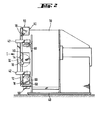
- a horizontal centrifuge is shown schematically, in which the axis of rotation of the drum is horizontal.
- the centrifuge is mounted on a housing support 40.
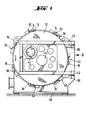
- An end face of the approximately cylindrical housing 10 can be covered by the door 12, which is shown in plan view in FIG. 1.
- the door 12 is supported by two arms 42 (FIG. 1) which can be pivoted about the axis 60 in the manner of a hinge.
- a number of operating elements 44 (viewing windows, etc.) are arranged in the door, which are only shown schematically here, since they are not important.
- Fig. 1 7 devices 50 for locking the door of the centrifuge are shown schematically all around.
- the door 12 is firmly locked to the housing 10 by means of these devices 50 (see also FIG. 2).
- FIGS. 1 and 2 for locking the centrifuge door with the centrifuge housing are shown in detail in FIG. 3 in their embodiment according to the invention.
- Fig. 3 shows a single one of the seven devices shown in Fig. 1 for locking the door of the centrifuge.
- On the door 12 of the centrifuge receiving elements 16 are welded, in which hooks engage elements 14 in the locking position, which in turn are attached to the housing 10 of the centrifuge.
- Each device 50 has a receiving element 16 and a hook element 14.
- the hook elements 14 are attached to the housing 10 so as to be pivotable about an axis 20.
- the pivoting of the hook elements 14 about the axis 20 takes place pneumatically or hydraulically by means of a piston rod 28, which is moved in a known manner in a piston (not shown).
- the movement of the piston rod 28 takes place in the direction of the arrows 56.
- a block 46 is located on the piston rod 28, to which a joint bracket 30 is articulated at 54.
- the hinge bracket 30 is articulated with its other end section on the hook element 14 and can be pivoted about the axis 52.
- the pivoting of the joint plate 30 with respect to the holding element 14 is limited by means of a stop (not shown), so that during this movement the hook 24 of the hook element 14 is pressed firmly into the receiving element 16 becomes.
- the hook element 14 thus forms a lever which is pivotable about the axis 20 and one arm 22 carries the hook 24, while the other arm 26 represents the power arm on which the force-transmitting articulated bracket 30 acts.
- the piston rod 28 is moved downward with the block 46, the articulated lug 30 pivoting downward and the hook element 14 rotating about the axis 20 in such a way that it comes out of the receiving element 16 with the hook 24.
- each adjustable stops 32 are provided for the hook 24 of the Hakenelemen tes 14, which are adjustable, for example, by hand in such a way that a precisely fitting fit is ensured between all hook elements 14 and receiving elements 16 of a door lock.
- a set screw 64 which is locked by means of a lock nut 48, serves as stop 32.
- the locking position of the hook element 14 is detected by means of a proximity switch 34 which is connected to the control electronics of the centrifuge in such a way that rotation of the centrifuge is only possible when the holding elements 14 are locked.
- the damping lugs 36 for the proximity switches 34 are attached to the holding elements 14 in such a way that they are directly adjacent to the proximity switches 34 in the locking position.
Landscapes
- Centrifugal Separators (AREA)
Applications Claiming Priority (2)
| Application Number | Priority Date | Filing Date | Title |
|---|---|---|---|
| DE3409758 | 1984-03-16 | ||
| DE19843409758 DE3409758A1 (de) | 1984-03-16 | 1984-03-16 | Vorrichtung zum zuhalten der tuer einer zentrifuge |
Publications (1)
| Publication Number | Publication Date |
|---|---|
| EP0154983A2 true EP0154983A2 (fr) | 1985-09-18 |
Family
ID=6230759
Family Applications (1)
| Application Number | Title | Priority Date | Filing Date |
|---|---|---|---|
| EP19850102849 Withdrawn EP0154983A2 (fr) | 1984-03-16 | 1985-03-13 | Dispositif de verrouillage pour porte de centrifuge |
Country Status (4)
| Country | Link |
|---|---|
| EP (1) | EP0154983A2 (fr) |
| JP (1) | JPS60212257A (fr) |
| DE (1) | DE3409758A1 (fr) |
| GB (1) | GB8431345D0 (fr) |
Cited By (3)
| Publication number | Priority date | Publication date | Assignee | Title |
|---|---|---|---|---|
| AU609354B1 (en) * | 1989-07-31 | 1991-04-26 | Dideco S.R.L. | Device for closing the containment well of a blood centrifugation cell in a centrifugal machine |
| EP0577863A1 (fr) * | 1992-07-04 | 1994-01-12 | SIGMA LABORZENTRIFUGEN GmbH | Enceinte pour centrifugeuse |
| EP1136745A2 (fr) | 2000-03-22 | 2001-09-26 | Eppendorf Ag | Dispositif de verrouillage d'un organe de fermeture avec un boitier |
Families Citing this family (2)
| Publication number | Priority date | Publication date | Assignee | Title |
|---|---|---|---|---|
| DE9417388U1 (de) * | 1994-10-29 | 1994-12-15 | Sigma Laborzentrifugen Gmbh, 37520 Osterode | Schließmechanismus für den Deckel einer Laborzentrifuge |
| JP6368934B2 (ja) * | 2014-08-27 | 2018-08-08 | 工機ホールディングス株式会社 | 遠心機 |
Family Cites Families (2)
| Publication number | Priority date | Publication date | Assignee | Title |
|---|---|---|---|---|
| DE1782569U (de) | 1958-08-22 | 1959-02-05 | Johann Berger | Traktorensitz aus schaumstoff. |
| DE7020665U (de) | 1970-06-03 | 1970-09-10 | Weininger Lothar | Verriegelung fuer den deckel einer maschine. |
-
1984
- 1984-03-16 DE DE19843409758 patent/DE3409758A1/de not_active Withdrawn
- 1984-12-12 GB GB848431345A patent/GB8431345D0/en active Pending
-
1985
- 1985-03-13 EP EP19850102849 patent/EP0154983A2/fr not_active Withdrawn
- 1985-03-15 JP JP5070385A patent/JPS60212257A/ja active Pending
Cited By (5)
| Publication number | Priority date | Publication date | Assignee | Title |
|---|---|---|---|---|
| AU609354B1 (en) * | 1989-07-31 | 1991-04-26 | Dideco S.R.L. | Device for closing the containment well of a blood centrifugation cell in a centrifugal machine |
| EP0577863A1 (fr) * | 1992-07-04 | 1994-01-12 | SIGMA LABORZENTRIFUGEN GmbH | Enceinte pour centrifugeuse |
| EP1136745A2 (fr) | 2000-03-22 | 2001-09-26 | Eppendorf Ag | Dispositif de verrouillage d'un organe de fermeture avec un boitier |
| DE10015010C2 (de) * | 2000-03-22 | 2002-08-29 | Eppendorf Ag | Verriegelung eines Verschlusses mit einem Gehäuse |
| EP1136745A3 (fr) * | 2000-03-22 | 2003-11-05 | Eppendorf Ag | Dispositif de verrouillage d'un organe de fermeture avec un boitier |
Also Published As
| Publication number | Publication date |
|---|---|
| JPS60212257A (ja) | 1985-10-24 |
| DE3409758A1 (de) | 1985-09-26 |
| GB8431345D0 (en) | 1985-01-23 |
Similar Documents
| Publication | Publication Date | Title |
|---|---|---|
| DE3872005T2 (de) | Zentrifugalseparator. | |
| DE2810620C2 (de) | Maschine zum Zusammenstecken von Schraubenrohlingen und ringförmigen Unterlegteilen | |
| DE102005014218A1 (de) | Befestigungsvorrichtung eines Deckels für einen Zentrifugenrotor | |
| DE3910801C2 (fr) | ||
| DE3207831C2 (de) | Drehschieberverschluß für Stahlschmelzbehälter | |
| EP0154983A2 (fr) | Dispositif de verrouillage pour porte de centrifuge | |
| DE102007040386B4 (de) | Vorrichtung zur Montage von Kleinteilen mit verbesserter Zufuhreinrichtung | |
| EP1713572A1 (fr) | Dispositif de dosage de produits en vrac | |
| WO1996034728A1 (fr) | Granulateur de matieres extrudees | |
| DE202016007625U1 (de) | Sensorhalterung für ein Fahrzeug | |
| DE3924792A1 (de) | Reifenmontiergeraet | |
| DE102010017826A1 (de) | Siebmaschine | |
| AT523406A4 (de) | Zerkleinerungsmaschine | |
| EP0145916A2 (fr) | Boîte de distribution | |
| EP0241765A1 (fr) | Machine d'étiquetage pour récipients | |
| DE3151737C2 (fr) | ||
| DE3100781A1 (de) | "anpressvorrichtung fuer die gestapelten filterelemente eines fluessigkeitsfilters" | |
| EP1057904A1 (fr) | Appareil pour loger et positionner des chapeaux fixes sur des machines de cardages | |
| DE3231024A1 (de) | Abpratzvorrichtung fuer aussenlasten an flugzeugen | |
| EP0562270A1 (fr) | Epandeur, spécialement distributeur d'engrais centrifuge | |
| DE2734067C2 (de) | Geräte-Aufnahmebehälter für ein Kraftfahrzeug-Armaturenbrett, insbesondere zur Aufnahme eines Fahrtenschreibers | |
| DE3507815A1 (de) | Vorrichtung zur automatischen entnahme von gegenstaenden aus behaeltern | |
| DE3830369C2 (fr) | ||
| DE2328439B2 (de) | Schwenkbarer Werkstück-Aufspanntisch für Werkzeugmaschinen, Insbesondere für Universal-Fräsmaschlnen | |
| DE916521C (de) | Einstellvorrichtung fuer elektrostatische Scheider |
Legal Events
| Date | Code | Title | Description |
|---|---|---|---|
| PUAI | Public reference made under article 153(3) epc to a published international application that has entered the european phase |
Free format text: ORIGINAL CODE: 0009012 |
|
| AK | Designated contracting states |
Designated state(s): AT BE CH FR GB IT LI NL SE |
|
| STAA | Information on the status of an ep patent application or granted ep patent |
Free format text: STATUS: THE APPLICATION HAS BEEN WITHDRAWN |
|
| 18W | Application withdrawn |
Withdrawal date: 19870126 |
|
| RIN1 | Information on inventor provided before grant (corrected) |
Inventor name: VOLLATH, WILHELM Inventor name: KISSLINGER, WALTER, ING. (GRAD) |