EP0155010A2 - Procédé de fabrication d'un masque d'ombre pour tube image - Google Patents
Procédé de fabrication d'un masque d'ombre pour tube image Download PDFInfo
- Publication number
- EP0155010A2 EP0155010A2 EP85103032A EP85103032A EP0155010A2 EP 0155010 A2 EP0155010 A2 EP 0155010A2 EP 85103032 A EP85103032 A EP 85103032A EP 85103032 A EP85103032 A EP 85103032A EP 0155010 A2 EP0155010 A2 EP 0155010A2
- Authority
- EP
- European Patent Office
- Prior art keywords
- mask
- shadow mask
- darkened
- atmosphere
- annealing
- Prior art date
- Legal status (The legal status is an assumption and is not a legal conclusion. Google has not performed a legal analysis and makes no representation as to the accuracy of the status listed.)
- Granted
Links
Images
Classifications
-
- H—ELECTRICITY
- H01—ELECTRIC ELEMENTS
- H01J—ELECTRIC DISCHARGE TUBES OR DISCHARGE LAMPS
- H01J9/00—Apparatus or processes specially adapted for the manufacture, installation, removal, maintenance of electric discharge tubes, discharge lamps, or parts thereof; Recovery of material from discharge tubes or lamps
- H01J9/02—Manufacture of electrodes or electrode systems
- H01J9/14—Manufacture of electrodes or electrode systems of non-emitting electrodes
- H01J9/142—Manufacture of electrodes or electrode systems of non-emitting electrodes of shadow-masks for colour television tubes
Definitions
- the present invention relates to a method of manufacturing a picture tube shadow mask and, more particularly, to a method of manufacturing a shadow mask of an Fe-Ni alloy.
- a high-purity, low-carbon steel plate of rimmed steel or aluminum killed steel has been used for a color picture tube shadow mask.
- the use of this material was determined in consideration of material supply capacity, manufacturing cost, machining properties, and mechanical strength.
- such a conventional material has a large thermal expansion coefficient (about 12 x 10- 6 /° C for 0 to 100°C).
- the electron beam transmittance of a conventional shadow mask is about 15 to 20%, and many electron beams impinge thereupon, so that the shadow mask itself is heated to a temperature of 30 to 80°C.
- the shadow mask is thermally deformed, changing the radius of curvature thereof with respect to a phosphor screen, thereby degrading color purity.
- Such degradation is called a purity drift (PD).
- a wide margin (to be referred to as a guard band quantity hereinafter) for a positional error between the phosphor screen and the electron beam is guaranteed. Even if the shadow mask is thermally deformed to some extent, degradation of color impurity tends not to occur.
- the above-mentioned margin is not always sufficient.
- the aperture pitch is very small
- the aperture size itself is also small (140 ⁇ m at a pitch of 0.3 mm, or 85 ⁇ m at a pitch of 0.2 mm).
- the guard band quantity is inevitably small.
- the mask plate in order to obtain such a small aperture size by photo- etching, the mask plate must have a small thickness, thereby decreasing the heat capacity. As compared with a thick plate, the thermal expansion quantity of such a thin mask plate is increased under identical conditions, thereby degrading the color purity.
- the radius of the curvature of the mask is larger than that of a normal color picture tube. Even if the mask of the flat tube is subjected to the same thermal expansion influence as in the normal tube, the electron beams passing through the mask apertures are greatly deviated from the target positions on the phosphor screen. In addition to this disadvantage, since the pitch is small, the guard band quantity is small, and the color purity tends to be degraded.. In order to resolve the above problems, various methods have been proposed. For example, in Japanese Patent Publication No. 42-25446 and Japanese Patent Disclosure Nos.
- an iron-nickel alloy having a small thermal expansion coefficient e.g., a 36% Ni-Fe Invar alloy (having a thermal expansion coefficient of about 0 to 2.0 x 10- 6 / °C for 0 to 100°C) or a 42% Ni-Fe alloy (having a thermal expansion coefficient of about 5.0 x 10 -6 °C for 0 to 100°C) is used as a material for a shadow mask.
- a 36% Ni-Fe Invar alloy having a thermal expansion coefficient of about 0 to 2.0 x 10- 6 / °C for 0 to 100°C
- a 42% Ni-Fe alloy having a thermal expansion coefficient of about 5.0 x 10 -6 °C for 0 to 100°C
- the shadow mask must have a surface curved with high precision. Tolerance for the radius R of curvature of 1,000 mm is as strict as ⁇ 5 mm.
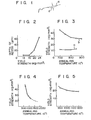
- the Fe-Ni alloy has a high mechanical strength and a poor spherical formability by pressing or the like even after annealing under the same conditiohs. For example, as shown in Fig.
- a depth d of the recess which is not more than 20 ⁇ m substantially satisfies the tolerance requirement for color purity.
- Fig. 2 is a graph showing the recess depth as a function of the yield strength in a 14 inch type shadow mask. As apparent from Fig. 2, the yield strength must be less than 20 kg/mm2 so as to limit the depth to 20 ⁇ m or less.
- the yield strength (a curve b) of the Fe-Ni alloy is higher than the yield strength (a curve a) of the aluminum killed low-carbon steel, as shown in Fig. 3.
- the yield strength of the Fe-Ni alloy is decreased only to 29 to 30 kg/m- 2 even if it is annealed at a high temperature of 900°C.
- the yield strength of the Fe-Ni alloy does not show a yield phenomenon inherent to carbon steel and is represented by the tensile strength when the Fe-Ni alloy is elongated by 0.2%.
- the effective peripheral portion of the shadow mask of the Fe-Ni alloy material is particularly subject to deformation and recessing, thereby presenting the problem of degradation in color purity due to deformation.
- a desired curved surface is obtained by pressing and a darkened oxide layer (to be referred to as a darkened layer hereinafter) is formed on the surface of the shadow mask.
- the darkened layer need not be formed on the Fe-Ni shadow mask due to the presence of Ni having good anticorrosion properties
- a typical difference between the electron beam mobility (i.e., PD quantity) of the Fe-Ni alloy without the darkened layer caused by thermal deformation thereof and that of the aluminum killed low carbon steel cannot be observed even if the Fe-Ni has a small thermal expansion coefficient. This is because heat radiation is degraded since the darkened layer is not formed on the shadow mask, and a thermal conductivity of the Fe-Ni alloy is lower than that of the aluminum killed low-carbon steel.
- the Fe-Ni shadow mask has a higher temperature than that of the low-carbon steel shadow mask.
- the darkened layer having good heat radiation is formed on the shadow mask, the low thermal expansion of the Fe-Ni material cannot be effectively utilized, resulting in degradation of color purity caused by thermal deformation.
- the darkened layer tends to be nonuniform due to impurities contained in the Fe-Ni alloy or surface contamination of the Fe-Ni mask. Consequently, a red rust is partially formed on the surface of the Fe-Ni mask.
- the darkened layer peels from the surface of the Fe-Ni alloy. Rust increases in the area of red rust formation during subsequent heat treatment to vary the aperture sizes. As compared with the darkened layer, the red rust layer more easily peels from the Fe-Ni material. The peeled, darkened and red rust layers cause a decrease in breakdown voltage, resulting in a notable disadvantage to the color picture tube.
- WU white uniformity
- a method of manufacturing a picture tube shadow mask having at least the steps of forming a plurality of mask apertures in a thin metal plate having iron and nickel as major constituents, annealing the metal plate with the plurality of mask apertures, and forming a darkened oxide layer on the annealed metal plate, wherein a cooling after annealing is performed in a reducing atmosphere, and the darkened oxide layer is formed in a weakly oxidizing steam atmosphere during a first half period and in a strongly oxidizing steam atmosphere during a second half period.
- annealing of the shadow mask of an Fe-Ni alloy is performed before the shadow mask is pressed.
- the shadow mask is annealed, it is cooled in a reducing atmosphere in a furnace, thereby decreasing the yield strength of the shadow mask.
- the Fe-Ni material is pressed to control the radius of curvature.
- the surface of the shadow mask is prevented from being converted to stainless steel so as to obtain a surface which easily allows a growth of an oxide film.
- a darkened oxide film is formed in a weakly oxidizing atmosphere in a heating furnace during the first half period and in a strongly oxidizing atmosphere during the second half period.
- the darkened oxide film formed in this manner has a high density, good adhesion strength, sufficient darkness and a uniform thickness.
- annealing if performed in a vacuum, is performed at a temperature of 1,000°C or higher, preferably within the range of 1000 to 1200°C at a pressure of 10 -1 torr or higher, preferably within the range of 10-1 to 10 -5 torr.
- the shadow mask is then cooled in a reducing atmosphere, e.g., hydrogen gas to a temperature of about 500°C.
- the darkened layer is formed in a steam atmosphere obtained by supplying steam to a furnace at a rate of 20 to 50 m 3 /hr per unit volume of the furnace at a temperature of 500 to 700° for 10 minutes or more as the first half period.
- steam is supplied at a rate of 0 to 20 m 3 /hr per unit volume of the furnace at a temperature of 550 to 750°C.
- the oxidation effect can be gradually increased without providing the first and second half periods for weak and strong oxidizing effects.
- the shadow mask is preferably kept in a deoxidizing atmosphere after the annealing step until the step of forming a darkened layer is initiated.
- Fig. 4 shows the yield strength of a shadow mask having a 36 Ni Invar alloy when the annealing temperature is increased while the shadow mask is placed in a hydrogen atmosphere (having a dew point of 10°C) in an annealing furnace.
- the yield strength thereof is decreased only to 24 kg/mm 2 .
- the annealing temperature must fall within the range of 1,500 to 1,700°C from extrapolation with reference to Fig. 4.
- the melting point of the Invar alloy is 1,440 to 1,450°C, such annealing cannot be performed.
- the present inventors examined the crystal structure of the annealed metal plate, and found that the inner crystal grains grew significantly upon an increase in the annealing temperature when hydrogen annealing was performed, but the crystal growth on the surface was very slight.
- the present inventors assumed that the insufficient surface crystal growth was associated with the yield strength and that the yield strength had to reach 20 kg/mm2 before the surface crystal grains would grow in the same manner as the inner crystal grains.
- a further assumption was made that Mn, P, S and the like having high vapor pressures among the impurities concentrated in the surface crystal interface could be evaporated to accelerate the surface crystal grain growth.
- Annealing was performed in a vacuum of 10 -2 torr at a temperature of 900 to 1,200°C for 10 minutes. As shown in Fig. 5, a yield strength of 20 kg/mm2 or less could be obtained at a high annealing temperature of 1,000°C or higher. In this case, the surface crystal growth did not differ from the inner crystal growth. As is apparent from Table 2 showing the analysis results of impurities in the surface layer having a thickness of 1/20 or less of the entire thickness, impurities such as Mn, P and S are greatly decreased.
- the vacuum-annealed mask was pressed to obtain a smooth surface of high precision.
- the surface of the mask was then darkened in C0 2 +0 2 gas, air and steam atmospheres at a temperature of 560°C for 15 minutes. Only a thin blackish-purple oxide film was formed on the mask surface.
- the resultant mask was incorporated in a color picture tube, and the purity drift was measured. Even when the Invar material had a small thermal expansion coefficient, the purity drift was only slightly improved as compared with that of the aluminum-killed steel mask. This was because the darkened aluminum-killed steel mask had heat radiation of 0.6 and the darkened Invar mask 0.3 or less as compared to the completely darkened layer which is assumed to have a heat radiation of 1.
- the mask temperature in operation was measured by attaching a thermocouple to the mask surface.
- the temperature of the Invar mask was higher by 50 to 60°C than that of the aluminum-killed steel mask, thereby giving rise to a cause of a larger thermal deformation of the Invar mask.
- the same darkened oxide layer as in the aluminum-killed steel mask can be formed on the Invar mask to increase heat radiation.
- IMA ion microanalyzer
- the concentrated chromium was oxidized to form an inactive film having good anticorrosion properties, i.e., the surface was converted to stainless steel, and unlike Fe-Ni, growth of the oxide film on the surface was largely prevented.
- the present inventors then assumed that the chromium oxide formed on the surface of. the mask after annealing in a vacuum could be reduced and cooling could be performed in a reducing atmosphere to inhibit oxidation of the mask surface. After the mask was annealed at a temperature of 1,100°C and a vacuum pressure of 10- 2 torr for 10 minutes, the mask was cooled in the furnace while hydrogen was supplied thereto. When the mask was removed from the furnace upon cooling, it was covered with non-corrosion paper and was held in a case with a deoxidizer.
- the present inventors assumed that a thin darkened layer having good adhesion properties could be formed in the weak oxidizing atmosphere during the first half period and then in the strong oxidizing atmosphere during the second half period. Based upon this assumption, the present inventors made various tests. According to the present inventors, darkening was performed at a temperature of 500 to 700°C for 10 minutes or more while steam was supplied at a rate of 20 to 50 m 3 /hr per unit cubic meter of the reaction chamber during the first half period. Darkening was then continued at a temperature of 550 to 750°C for 10 minutes or more while steam was supplied at a rate of 0 to 20 m 3 /hr per unit cubic meter of the chamber.
- the darkened layer had sufficient darkness and good adhesion properties.
- the adhesion properties of the darkened layer were evaluated such that a 90° bending test followed by a peeling test of the darkened layer by adhesion of cellophane tape to the bent portion was made.
- the darkened layer state was observed through a scanning electron microscope.
- the resultant layer was a dense film without cracks and pinholes.
- layer quality varies due to different structures of darkening furnaces even if identical conditions are established. Therefore, proper conditions must be selected for a specific darkening furnace so as to fall within the above-mentioned ranges.
- darkening need not be performed under different conditions during the first and second half periods. The oxidation effect can be changed in steps from a weak to a strong effect by changing the amount of steam and temperature.
- the 36 Ni Invar alloy is used as the shadow mask material.
- the present invention is not limited to this material.
- any Fe-Ni alloy containing super Invar, such as 42 Ni alloy and 32 Ni-5Co can be used.
- the darkening method of the present invention can also be used for an Fe-Ni alloy such as a mask frame and an inner shield which are incorporated in a color picture tube, in addition to a shadow mask.
- the annealing process in the present invention may be carried out in an ordinary hydrogen atmosphere as disclosed in Japanese Patent Disclosure No. 59-200721 by adopting molding strain-diminishing measures such as a hot-pressing or by making smooth the boundary portion between the central curved portion and outer fringe portion of the shadow mask, in which a molding strain is likely to be concentrated at the time of a press molding.
- the darkened oxide film has good pressing, anticorrosion and heat radiation properties.
- a shadow mask of an Fe-Ni alloy having good white uniformity quality and free from purity drift can be obtained.
Landscapes
- Engineering & Computer Science (AREA)
- Manufacturing & Machinery (AREA)
- Electrodes For Cathode-Ray Tubes (AREA)
Applications Claiming Priority (4)
| Application Number | Priority Date | Filing Date | Title |
|---|---|---|---|
| JP59048145A JPS60194012A (ja) | 1984-03-15 | 1984-03-15 | シヤドウマスクの製造方法 |
| JP48147/84 | 1984-03-15 | ||
| JP48145/84 | 1984-03-15 | ||
| JP59048147A JPH0680182B2 (ja) | 1984-03-15 | 1984-03-15 | シヤドウマスクの製造方法 |
Publications (3)
| Publication Number | Publication Date |
|---|---|
| EP0155010A2 true EP0155010A2 (fr) | 1985-09-18 |
| EP0155010A3 EP0155010A3 (en) | 1986-12-17 |
| EP0155010B1 EP0155010B1 (fr) | 1988-09-21 |
Family
ID=26388370
Family Applications (1)
| Application Number | Title | Priority Date | Filing Date |
|---|---|---|---|
| EP85103032A Expired EP0155010B1 (fr) | 1984-03-15 | 1985-03-15 | Procédé de fabrication d'un masque d'ombre pour tube image |
Country Status (5)
| Country | Link |
|---|---|
| US (1) | US4612061A (fr) |
| EP (1) | EP0155010B1 (fr) |
| DE (1) | DE3565191D1 (fr) |
| HK (1) | HK109390A (fr) |
| SG (1) | SG95490G (fr) |
Cited By (4)
| Publication number | Priority date | Publication date | Assignee | Title |
|---|---|---|---|---|
| EP0284233A1 (fr) * | 1987-03-07 | 1988-09-28 | Kabushiki Kaisha Toshiba | Four pour la réalisation d'une couche d'oxyde noir sur une feuille métallique et procédé d'application d'une couche d'oxyde noir sur la surface d'un masque d'ombre à l'aide de ce four |
| FR2664908A1 (fr) * | 1990-07-17 | 1992-01-24 | Nippon Kokan Kk | Feuille d'alliage fer-nickel pour masque de tube de television. |
| US5252151A (en) * | 1990-02-15 | 1993-10-12 | Nkk Corporation | Fe-Ni alloy sheet for shadow mask having a low silicon segregation and method for manufacturing same |
| DE4439440A1 (de) * | 1994-11-04 | 1996-05-09 | Nokia Deutschland Gmbh | Vorrichtung zur Aufrechterhaltung eines Oxydationsprozesses |
Families Citing this family (12)
| Publication number | Priority date | Publication date | Assignee | Title |
|---|---|---|---|---|
| US4771213A (en) * | 1985-10-30 | 1988-09-13 | Kabushiki Kaisha Toshiba | Shadow mask |
| NL8600141A (nl) * | 1986-01-23 | 1987-08-17 | Philips Nv | Werkwijze voor het vervaardigen van een schaduwmasker, schaduwmasker vervaardigd volgens zulk een werkwijze en kleurenbeeldbuis voorzien van zulk een schaduwmasker. |
| EP0259979A3 (fr) * | 1986-09-12 | 1989-03-08 | Hitachi, Ltd. | Méthode de fabrication d'un masque d'ombre d'un tube à rayons cathodiques |
| US4904218A (en) * | 1987-12-02 | 1990-02-27 | Zenith Electronics Corporation | Blackening of non-iron-based flat tensioned foil shadow masks |
| JPH03208225A (ja) * | 1990-01-09 | 1991-09-11 | Mitsubishi Electric Corp | シャドウマスクの製造方法 |
| US5078812A (en) * | 1990-10-09 | 1992-01-07 | Rca Thomson Licensing Corp. | Method for darkening a color-selection electrode |
| US5292274A (en) * | 1993-03-25 | 1994-03-08 | Thomson Consumer Electronics, Inc. | Method of manufacturing a color CRT to optimize the magnetic performance |
| KR100213772B1 (ko) * | 1996-10-25 | 1999-08-02 | 구자홍 | 칼라브라운관용 새도우마스크구조 |
| JP2002160246A (ja) * | 2000-11-22 | 2002-06-04 | Seibu:Kk | クランプ付金型及びクランプ付金型を用いたプレス成型方法 |
| US20020092583A1 (en) * | 2001-01-16 | 2002-07-18 | Pelton Alan R. | Medical devices, particularly stents, and methods for their manufacture |
| US20040117001A1 (en) * | 2001-01-16 | 2004-06-17 | Pelton Alan R. | Medical devices, particularly stents, and methods for their manufacture |
| EP1388160A2 (fr) * | 2001-04-25 | 2004-02-11 | Koninklijke Philips Electronics N.V. | Procede de production de tube ecran couleur a modele perfectionne d'electrode de selection des couleurs |
Family Cites Families (7)
| Publication number | Priority date | Publication date | Assignee | Title |
|---|---|---|---|---|
| US3708351A (en) * | 1970-02-02 | 1973-01-02 | Tubal Ind Inc | Blackening process |
| JPS4962073A (fr) * | 1972-10-18 | 1974-06-15 | ||
| US3925109A (en) * | 1974-01-29 | 1975-12-09 | Us Energy | Precise carbon control of fabricated stainless steel |
| US3935036A (en) * | 1974-02-19 | 1976-01-27 | Zenith Radio Corporation | Method of forming a dark, very adherent coating on a CRT mask assembly |
| US4285106A (en) * | 1979-12-13 | 1981-08-25 | Gte Laboratories Incorporated | Method for producing color cathode ray tube aperture masks |
| DE3366460D1 (en) * | 1982-08-05 | 1986-10-30 | Toshiba Kk | Color picture tube and method for manufacturing the same |
| FR2532108A1 (fr) * | 1982-08-20 | 1984-02-24 | Videocolor Sa | Procede de preparation des pieces ferreuses d'un tube de television en couleurs et four pour la mise en oeuvre d'un tel procede |
-
1985
- 1985-03-12 US US06/710,979 patent/US4612061A/en not_active Expired - Lifetime
- 1985-03-15 DE DE8585103032T patent/DE3565191D1/de not_active Expired
- 1985-03-15 EP EP85103032A patent/EP0155010B1/fr not_active Expired
-
1990
- 1990-11-23 SG SG954/90A patent/SG95490G/en unknown
- 1990-12-27 HK HK1093/90A patent/HK109390A/en not_active IP Right Cessation
Cited By (4)
| Publication number | Priority date | Publication date | Assignee | Title |
|---|---|---|---|---|
| EP0284233A1 (fr) * | 1987-03-07 | 1988-09-28 | Kabushiki Kaisha Toshiba | Four pour la réalisation d'une couche d'oxyde noir sur une feuille métallique et procédé d'application d'une couche d'oxyde noir sur la surface d'un masque d'ombre à l'aide de ce four |
| US5252151A (en) * | 1990-02-15 | 1993-10-12 | Nkk Corporation | Fe-Ni alloy sheet for shadow mask having a low silicon segregation and method for manufacturing same |
| FR2664908A1 (fr) * | 1990-07-17 | 1992-01-24 | Nippon Kokan Kk | Feuille d'alliage fer-nickel pour masque de tube de television. |
| DE4439440A1 (de) * | 1994-11-04 | 1996-05-09 | Nokia Deutschland Gmbh | Vorrichtung zur Aufrechterhaltung eines Oxydationsprozesses |
Also Published As
| Publication number | Publication date |
|---|---|
| US4612061A (en) | 1986-09-16 |
| HK109390A (en) | 1991-01-04 |
| SG95490G (en) | 1991-01-18 |
| EP0155010B1 (fr) | 1988-09-21 |
| DE3565191D1 (en) | 1988-10-27 |
| EP0155010A3 (en) | 1986-12-17 |
Similar Documents
| Publication | Publication Date | Title |
|---|---|---|
| EP0155010B1 (fr) | Procédé de fabrication d'un masque d'ombre pour tube image | |
| US4536226A (en) | Method of manufacturing a shadow mask for a color cathode ray tube | |
| JP2007231423A (ja) | 鉄/ニッケル合金のシャドーマスクの製造方法 | |
| US4665338A (en) | Front end elements for a color cathode ray tube | |
| EP0174196B1 (fr) | Matériau pour composants montés à l'intérieur de tubes cathodiques et son procédé de fabrication | |
| EP0280512A2 (fr) | Masque d'ombre en alliage fer-nickel pour tube image couleur | |
| US4596943A (en) | Shadow mask for a color picture tube | |
| EP0101919B1 (fr) | Tube image couleur et méthode pour sa fabrication | |
| JPS60128253A (ja) | エツチング時のスジむらの発生を抑制したシヤドウマスク用鉄−ニツケル基合金の製造方法 | |
| US4872924A (en) | Method of producing shadow mask of color cathode ray tube | |
| US4692659A (en) | Color cathode ray tube having shadow mask with silicon | |
| JPS5927435A (ja) | カラ−受像管 | |
| US6130500A (en) | Doming effect resistant shadow mask for cathode ray tube and its fabricating method | |
| EP0079738B1 (fr) | Composition métallique pour tube à rayons cathodiques en couleur | |
| US6316869B1 (en) | Shadow mask in color CRT | |
| KR890002363B1 (ko) | 새도우 마스크의 제조방법 | |
| JP3288656B2 (ja) | Fe−Ni系シャドウマスク用材料 | |
| JPH09111423A (ja) | Tvブラウン管用磁気シールド材およびその製造方法 | |
| EP1403393A1 (fr) | Fine feuille d'alliage a faible dilatation thermique, et masque perfore faisant intervenir son utilisation | |
| JPS60194059A (ja) | シヤドウマスクの製造方法 | |
| JPH0222496B2 (fr) | ||
| JPS6148523A (ja) | シヤドウマスクの製造方法 | |
| JPH0222495B2 (fr) | ||
| JPH0727760B2 (ja) | カラ−受像管 | |
| JPH09125206A (ja) | エッチング性に優れた電子部品用低熱膨張合金薄板 |
Legal Events
| Date | Code | Title | Description |
|---|---|---|---|
| PUAI | Public reference made under article 153(3) epc to a published international application that has entered the european phase |
Free format text: ORIGINAL CODE: 0009012 |
|
| 17P | Request for examination filed |
Effective date: 19850412 |
|
| AK | Designated contracting states |
Designated state(s): DE FR GB |
|
| PUAL | Search report despatched |
Free format text: ORIGINAL CODE: 0009013 |
|
| AK | Designated contracting states |
Kind code of ref document: A3 Designated state(s): DE FR GB |
|
| 17Q | First examination report despatched |
Effective date: 19871230 |
|
| GRAA | (expected) grant |
Free format text: ORIGINAL CODE: 0009210 |
|
| AK | Designated contracting states |
Kind code of ref document: B1 Designated state(s): DE FR GB |
|
| REF | Corresponds to: |
Ref document number: 3565191 Country of ref document: DE Date of ref document: 19881027 |
|
| ET | Fr: translation filed | ||
| PLBE | No opposition filed within time limit |
Free format text: ORIGINAL CODE: 0009261 |
|
| STAA | Information on the status of an ep patent application or granted ep patent |
Free format text: STATUS: NO OPPOSITION FILED WITHIN TIME LIMIT |
|
| 26N | No opposition filed | ||
| REG | Reference to a national code |
Ref country code: GB Ref legal event code: 746 Effective date: 19981008 |
|
| REG | Reference to a national code |
Ref country code: FR Ref legal event code: D6 |
|
| REG | Reference to a national code |
Ref country code: GB Ref legal event code: IF02 |
|
| PGFP | Annual fee paid to national office [announced via postgrant information from national office to epo] |
Ref country code: FR Payment date: 20040309 Year of fee payment: 20 |
|
| PGFP | Annual fee paid to national office [announced via postgrant information from national office to epo] |
Ref country code: GB Payment date: 20040310 Year of fee payment: 20 |
|
| PGFP | Annual fee paid to national office [announced via postgrant information from national office to epo] |
Ref country code: DE Payment date: 20040325 Year of fee payment: 20 |
|
| PG25 | Lapsed in a contracting state [announced via postgrant information from national office to epo] |
Ref country code: GB Free format text: LAPSE BECAUSE OF EXPIRATION OF PROTECTION Effective date: 20050314 |
|
| REG | Reference to a national code |
Ref country code: GB Ref legal event code: PE20 |