EP0155153A2 - Bandwiedergabegerät mit automatischer Laufrichtungsumkehr - Google Patents
Bandwiedergabegerät mit automatischer Laufrichtungsumkehr Download PDFInfo
- Publication number
- EP0155153A2 EP0155153A2 EP85301616A EP85301616A EP0155153A2 EP 0155153 A2 EP0155153 A2 EP 0155153A2 EP 85301616 A EP85301616 A EP 85301616A EP 85301616 A EP85301616 A EP 85301616A EP 0155153 A2 EP0155153 A2 EP 0155153A2
- Authority
- EP
- European Patent Office
- Prior art keywords
- tape
- circuit
- mode
- state
- detecting circuit
- Prior art date
- Legal status (The legal status is an assumption and is not a legal conclusion. Google has not performed a legal analysis and makes no representation as to the accuracy of the status listed.)
- Granted
Links
Images


Classifications
-
- G—PHYSICS
- G11—INFORMATION STORAGE
- G11B—INFORMATION STORAGE BASED ON RELATIVE MOVEMENT BETWEEN RECORD CARRIER AND TRANSDUCER
- G11B15/00—Driving, starting or stopping record carriers of filamentary or web form; Driving both such record carriers and heads; Guiding such record carriers or containers therefor; Control thereof; Control of operating function
- G11B15/18—Driving; Starting; Stopping; Arrangements for control or regulation thereof
- G11B15/44—Speed-changing arrangements; Reversing arrangements; Drive transfer means therefor
- G11B15/444—Speed-changing arrangements; Reversing arrangements; Drive transfer means therefor reversing arrangements
-
- G—PHYSICS
- G11—INFORMATION STORAGE
- G11B—INFORMATION STORAGE BASED ON RELATIVE MOVEMENT BETWEEN RECORD CARRIER AND TRANSDUCER
- G11B15/00—Driving, starting or stopping record carriers of filamentary or web form; Driving both such record carriers and heads; Guiding such record carriers or containers therefor; Control thereof; Control of operating function
- G11B15/02—Control of operating function, e.g. switching from recording to reproducing
- G11B15/05—Control of operating function, e.g. switching from recording to reproducing by sensing features present on or derived from record carrier or container
- G11B15/06—Control of operating function, e.g. switching from recording to reproducing by sensing features present on or derived from record carrier or container by sensing auxiliary features on record carriers or containers, e.g. to stop machine near the end of a tape
- G11B15/08—Control of operating function, e.g. switching from recording to reproducing by sensing features present on or derived from record carrier or container by sensing auxiliary features on record carriers or containers, e.g. to stop machine near the end of a tape by photoelectric sensing
-
- G—PHYSICS
- G11—INFORMATION STORAGE
- G11B—INFORMATION STORAGE BASED ON RELATIVE MOVEMENT BETWEEN RECORD CARRIER AND TRANSDUCER
- G11B15/00—Driving, starting or stopping record carriers of filamentary or web form; Driving both such record carriers and heads; Guiding such record carriers or containers therefor; Control thereof; Control of operating function
- G11B15/02—Control of operating function, e.g. switching from recording to reproducing
- G11B15/05—Control of operating function, e.g. switching from recording to reproducing by sensing features present on or derived from record carrier or container
- G11B15/087—Control of operating function, e.g. switching from recording to reproducing by sensing features present on or derived from record carrier or container by sensing recorded signals
-
- G—PHYSICS
- G11—INFORMATION STORAGE
- G11B—INFORMATION STORAGE BASED ON RELATIVE MOVEMENT BETWEEN RECORD CARRIER AND TRANSDUCER
- G11B27/00—Editing; Indexing; Addressing; Timing or synchronising; Monitoring; Measuring tape travel
- G11B27/10—Indexing; Addressing; Timing or synchronising; Measuring tape travel
- G11B27/19—Indexing; Addressing; Timing or synchronising; Measuring tape travel by using information detectable on the record carrier
- G11B27/22—Means responsive to presence or absence of recorded information signals
-
- G—PHYSICS
- G11—INFORMATION STORAGE
- G11B—INFORMATION STORAGE BASED ON RELATIVE MOVEMENT BETWEEN RECORD CARRIER AND TRANSDUCER
- G11B27/00—Editing; Indexing; Addressing; Timing or synchronising; Monitoring; Measuring tape travel
- G11B27/10—Indexing; Addressing; Timing or synchronising; Measuring tape travel
- G11B27/19—Indexing; Addressing; Timing or synchronising; Measuring tape travel by using information detectable on the record carrier
- G11B27/24—Indexing; Addressing; Timing or synchronising; Measuring tape travel by using information detectable on the record carrier by sensing features on the record carrier other than the transducing track ; sensing signals or marks recorded by another method than the main recording
- G11B27/26—Indexing; Addressing; Timing or synchronising; Measuring tape travel by using information detectable on the record carrier by sensing features on the record carrier other than the transducing track ; sensing signals or marks recorded by another method than the main recording by photoelectric detection, e.g. of sprocket holes
Definitions
- the invention relates to tape recording and/or reproducing apparatus of automatic reversing type which will automatically change the direction in which the magnetic tape is running.
- an optical device is arranged close to the tape path for detecting the difference in the optical characteristics of the tape between the portion where magnetic particles are coated and the leader portions which are attached to both ends of the coated portion. For detecting the actual tape end, it is necessary to distinguish whether the detected leader portion is attached to the beginning of the coated portion or to the end.
- an electronic device is coupled to the optical device for that purpose.
- the electronic device includes, for example, an integrating circuit having a certain time constant which provides sufficient time for the leader portion attached to the beginning of the coated portion to pass through the optical device, for preventing misoperation.
- the above method can be used in an apparatus of automatic reversing type which will automatically change the direction of the tape at the tape end.
- the change of direction shall occur as soon as possible at the end of the coated portion.
- Various electronic circuits for example, a combination of a differentiating or integrating circuit and a logic circuit, have been proposed for this purpose, but these circuits, which are only needed to detect the end of the coated portion, are complicated and expensive, so increasing the price of the apparatus.
- a tape recording and/or reproducing apparatus of automatic reversing type comprising:
- a tape recording and/or reproducing apparatus of automatic reversing type which comprises a first detecting circuit for generating an output signal which changes from one state to another state only when the end of a coated portion of a tape is detected by a sensor, a second detecting circuit for generating an output signal which changes from one state to another state only when a non-recorded portion of the tape is detected, and a third detecting circuit to which output signals of the first and the second detecting circuits are supplied for generating a switching signal to change the mode of apparatus when either of the output signals is maintained in said other state for a predetermined time as measured by a common time constant circuit.
- the third detecting circuit includes an integrating circuit which has a certain time constant so as to distinguish a pianissimo part of the sound signal from the non-recorded portion of the tape in the fast-forward or fast-rewind mode of the apparatus, and also to distinguish a damaged portion of the tape, for example a portion where the magnetic particles have been partially worn off, from the end of the coated portion, in the forward mode.
- the time constant can be made small, because the output signal of the second detecting circuit is generated only when the end (not the beginning) of the coated portion of the tape is detected so the change of direction can be effected quickly at the end of the coated portion.
- a magnetic tape contained in a cassette has a magnetically coated portion carrying the magnetic recording material and two leader portions each say 10 cms long, which are transparent and attached to respective ends of the coated portion.
- One of the methods which has been developed for detecting the end of the tape uses an optical device which is arranged close to the tape path and can detect the difference in the optical characteristics of the coated portion and the leader portions.
- Figure 1 shows an example of such a detecting circuit.
- an optical device OD comprises, for example, an electro-luminescent diode ECD and a photo-transistor PT which are arranged close to respective sides of the tape path.
- the detecting circuit comprises the optical device OD and switching transistors Ql and Q2, and an integrating circuit T.
- a DC voltage (Vcc) is supplied to the integrating circuit T when either of the leader portions is detected by the optical device OD.
- Vcc DC voltage
- a time constant which is determined by a resistor R and a capacitor C of the integrating circuit T is made large enough to make the switching transistor Q2 turn on only when the tape is fully wound.
- the magnetic head reproduces the recorded signals from the tape which is running at high-speed, and a rectifying circuit to which the reproduced signals is supplied, and logic circuits are combined to detect a non-recorded portion of the tape.
- AMS Automatic Music Sensor
- the detecting circuit for detecting the end of the coated portion of the tape is combined with another circuit for detecting a non-recorded portion of the tape.
- the detecting operation at the tape end is performed in the forward mode of the apparatus, and the detecting operation of the non-recorded portions is performed in the fast-forward or fast-rewind mode of the apparatus, so the common parts of the apparatus do not cause problems.
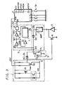
- one embodiment of the invention comprises a detecting circuit 1 for detecting the end of the coated portion of the tape, an integrating circuit 2 for detecting non-recorded portions of the tape and comprising a rectifying circuit 2a and a logic circuit 2b, an integrating circuit 3 having a certain time constant determined by a resistor r and a capacitor c, a control circuit 4 for generating respective control signals corresponding to several modes of the apparatus, and a playback amplifier 5 the output of which can be controlled by a muting transistor 6.
- the detecting circuit 1 comprises the optical device OD which operates as the previously proposed device shown in Figure 1, and a pair of switching transistors Q1 and Q2. As shown in Figure 4(a), the output signal of the detecting circuit 1 is "L" level when the leader portions are detected and both of the transistors Ql and Q2 turn on, and is "H” level when the coated portion of the tape is detected.
- the output terminal F/R of the control circuit 4 is connected to the base terminal of the transistor Q2, so that when the mode of apparatus is fast-forward or fast-rewind, the transistor Q2 is turned on by the signal coming from this loop, to keep the output at "L" level.
- the logic circuit 2b comprises a comparator CMP, invertors I 1 ans I 2 , a delay circuit L and an AND circuit A.
- One input terminal of the comparator CMP is connected to the outputs of the detecting circuit 1 and of the rectifying circuit 2a, and is also connected to the integrating circuit 3.
- the integrating circuit 3 will generate a signal having a certain voltage corresponding to the current coming from either of the detecting circuit 1 or the rectifying circuit 2a.
- the control circuit 4 has input terminals Il to Ir and output terminals Ol to Or. When one of operation switches Sl to Sr is depressed, at one of the output terminals Ol to Or will be developed a control signal corresponding to the selected mode of the apparatus, for controlling the tape-drive mechanism. When the switching signal is supplied to the input terminal IN of the control circuit 4, the control circuit 4 operates to automatically change the mode of the apparatus from the fast-forward mode if the AMS mode has been previously set by the one of the switches, and on the other hand, operates automatically to change the running direction of the tape if the forward or reverse-forward mode has previously been set by another of the switches.
- the integrating circuit 3 being already charged to a certain voltage level etl corresponding to the current from the detecting circuit 1 during the playback mode, will be charged to another voltage level et2 corresponding to the current from the diode Dl.
- the rectifying signal disappears from the time T2 shown in Figure 4(c) when the non-recorded portion is reached, so that the output voltage et2 of the integrating circuit 3 is discharged along the curve ⁇ o, being determined by the time constant (ro x Co). If the non-recorded portion is detected continuously for a certain time To, for example 40 to 100 ms in the fast-forward or fast-rewind mode, which corresponds to at least 1 sec in the forward mode, and is used to distinguish a pianissimo part from a non-recorded portion, the comparator CMP begins to operate from the point where the discharge curve ⁇ o crosses the reference voltage Er.
- Invertors Il and 12 operate in known manner to detect only the change from "H" level to "L” level, and an output pulse PI of the AND circuit A is supplied to the terminal IN as shown in Figures 4(f), 4(g) and 4(h), so that the mode of the apparatus is changed to the forward or reverse-forward mode.
- the automatic reversing operation is performed as follows.
- the integrating circuit 3 is charged to a certain level etl by the current signal from the diode Dl, but when the leader portion at the end of the tape is detected by the optical device OD, the switching transistors Ql and Q2 turn on, so that the output of the detecting circuit 1 disappears at the time T4 shown in Figure 4(a). Therefore, the DC voltage of the integrating circuit 3 is discharged along the curve ⁇ o determined by the time constant (ro x Co).
- the comparator CMP begins to operate from the point where the discharging curve "C o crosses the reference voltage Er. Therefore, an output pulse P2 is supplied to the terminal IN as shown in Figures 4(f), 4(g) and 4(h), and the running direction of the tape reverses.
- the integrating circuit 3 is charged to a certain DC voltage by the incoming current in response to the mode, that is, the AMS mode or the automatic reversing mode, of the apparatus.
- the times to and tl can be set to different lengths respectively for the purpose of detection in each mode.
- this embodiment includes the logic circuit 2b for detecting the change of the signal only from “H” level to "L” level, it could be modified to detect the change of the signal only from “L” level to "H” level.
Landscapes
- Indexing, Searching, Synchronizing, And The Amount Of Synchronization Travel Of Record Carriers (AREA)
- Digital Magnetic Recording (AREA)
Applications Claiming Priority (2)
| Application Number | Priority Date | Filing Date | Title |
|---|---|---|---|
| JP48195/84 | 1984-03-15 | ||
| JP59048195A JPS60193151A (ja) | 1984-03-15 | 1984-03-15 | テ−プエンド検出回路 |
Publications (3)
| Publication Number | Publication Date |
|---|---|
| EP0155153A2 true EP0155153A2 (de) | 1985-09-18 |
| EP0155153A3 EP0155153A3 (en) | 1987-05-20 |
| EP0155153B1 EP0155153B1 (de) | 1990-12-05 |
Family
ID=12796599
Family Applications (1)
| Application Number | Title | Priority Date | Filing Date |
|---|---|---|---|
| EP85301616A Expired - Lifetime EP0155153B1 (de) | 1984-03-15 | 1985-03-08 | Bandwiedergabegerät mit automatischer Laufrichtungsumkehr |
Country Status (6)
| Country | Link |
|---|---|
| US (1) | US4636878A (de) |
| EP (1) | EP0155153B1 (de) |
| JP (1) | JPS60193151A (de) |
| KR (1) | KR930003426B1 (de) |
| CA (1) | CA1232680A (de) |
| DE (1) | DE3580772D1 (de) |
Families Citing this family (8)
| Publication number | Priority date | Publication date | Assignee | Title |
|---|---|---|---|---|
| US5005088A (en) * | 1986-05-21 | 1991-04-02 | Canon Kabushiki Kaisha | Recording and/or reproducing apparatus adapted to minimize electrical energy consumption |
| US5008762A (en) * | 1989-07-10 | 1991-04-16 | Samsung Electronics Co., Ltd. | Parallel and continuous playback circuit for an audio cassette deck of the double-deck type |
| KR920006318B1 (ko) * | 1990-03-21 | 1992-08-03 | 삼성전자 주식회사 | 기록재생시스템의 자동서치장치 |
| US5152477A (en) * | 1990-08-01 | 1992-10-06 | Yeh Tsun W | Electronic detection device for detecting the ending of the rewinding of a video cassette rewinder |
| JP2825340B2 (ja) * | 1990-11-22 | 1998-11-18 | キヤノン株式会社 | テープ端検出装置 |
| US5644447A (en) * | 1991-03-01 | 1997-07-01 | Canon Kabushiki Kaisha | Recording or reproducing apparatus having function of searching for unrecorded part |
| KR940004499B1 (ko) * | 1991-12-23 | 1994-05-25 | 금성일렉트론 주식회사 | 브이 씨 알의 종단 기록 및 검출 회로 |
| KR970017294A (ko) * | 1995-09-26 | 1997-04-30 | 김광호 | 녹화시 테이프의 기 기록된 구간의 보호 방법 및 그 장치 |
Family Cites Families (7)
| Publication number | Priority date | Publication date | Assignee | Title |
|---|---|---|---|---|
| JPS5237764B2 (de) * | 1972-09-05 | 1977-09-24 | ||
| US3846831A (en) * | 1973-03-07 | 1974-11-05 | Micro Communications Corp | Sound reproducing apparatus in which the drive means operates in response to a prerecorded control signal |
| JPS5713636Y2 (de) * | 1976-10-20 | 1982-03-19 | ||
| DE2837598A1 (de) * | 1977-09-10 | 1979-03-22 | Ii Peter Copeland | Steuereinrichtung |
| JPS6017066Y2 (ja) * | 1979-02-02 | 1985-05-27 | オリンパス光学工業株式会社 | テ−プレコ−ダ |
| JPS56117352A (en) * | 1980-02-18 | 1981-09-14 | Sanyo Electric Co Ltd | Tape run control circuit for tape recorder |
| GB2096381B (en) * | 1981-04-03 | 1985-03-20 | Pioneer Electronic Corp | Device for detecting a non-recorded segment on magnetic tape |
-
1984
- 1984-03-15 JP JP59048195A patent/JPS60193151A/ja active Granted
-
1985
- 1985-03-08 DE DE8585301616T patent/DE3580772D1/de not_active Expired - Lifetime
- 1985-03-08 EP EP85301616A patent/EP0155153B1/de not_active Expired - Lifetime
- 1985-03-12 KR KR1019850001568A patent/KR930003426B1/ko not_active Expired - Fee Related
- 1985-03-14 US US06/711,753 patent/US4636878A/en not_active Expired - Lifetime
- 1985-03-14 CA CA000476495A patent/CA1232680A/en not_active Expired
Also Published As
| Publication number | Publication date |
|---|---|
| CA1232680A (en) | 1988-02-09 |
| DE3580772D1 (de) | 1991-01-17 |
| EP0155153B1 (de) | 1990-12-05 |
| JPH0563847B2 (de) | 1993-09-13 |
| EP0155153A3 (en) | 1987-05-20 |
| US4636878A (en) | 1987-01-13 |
| KR930003426B1 (ko) | 1993-04-29 |
| KR850006952A (ko) | 1985-10-25 |
| JPS60193151A (ja) | 1985-10-01 |
Similar Documents
| Publication | Publication Date | Title |
|---|---|---|
| US4228471A (en) | Apparatus for searching a piece of information recorded on a magnetic tape | |
| EP0155153A2 (de) | Bandwiedergabegerät mit automatischer Laufrichtungsumkehr | |
| US4583669A (en) | Apparatus for detecting a tape splice | |
| US3711657A (en) | Control device for a tape recorder for detecting the beginning of a desired program | |
| US4357636A (en) | Magnetic tape device | |
| EP0632453B1 (de) | Verfahren zur Wiederaufnahme der Wiedergabe eines Kassettenbandes beim Anfang des Musikstückes, das gespielt wurde nach Abschalten und anschliessendem Wiedereinschalten des Gerätes | |
| US5519549A (en) | VISS circuit for preventing image search malfunction occurring due to variation in speed of video tape | |
| US4574320A (en) | Dictating machine having a revising function | |
| JPS59218649A (ja) | 磁気記録再生装置 | |
| KR0123305Y1 (ko) | 카셋트테이프의 재생시간감지장치 | |
| JPS6029060Y2 (ja) | 曲間無録音部検出装置 | |
| KR840002013Y1 (ko) | 자동판매기의 판매시에 있어서 음악 송출장치 | |
| JPH0210584Y2 (de) | ||
| KR910002496B1 (ko) | 자기테이프의 자동 선곡 회로 | |
| JP3147746B2 (ja) | 選曲装置 | |
| JPS5817557A (ja) | テ−ププレ−ヤ | |
| JP2581671B2 (ja) | デイスクダビング装置 | |
| JP2641435B2 (ja) | テープ頭出し選択装置 | |
| JPS58158066A (ja) | 磁気記録再生装置 | |
| KR920001208Y1 (ko) | 음향기기의 자동 더빙 회로 | |
| JPS5968856A (ja) | 選曲回路 | |
| JPS5817556A (ja) | テ−ププレ−ヤ | |
| JPH0344398B2 (de) | ||
| JPH07147038A (ja) | 無音自動スキップ再生装置 | |
| JPH0366738B2 (de) |
Legal Events
| Date | Code | Title | Description |
|---|---|---|---|
| PUAI | Public reference made under article 153(3) epc to a published international application that has entered the european phase |
Free format text: ORIGINAL CODE: 0009012 |
|
| AK | Designated contracting states |
Designated state(s): DE FR GB NL |
|
| PUAL | Search report despatched |
Free format text: ORIGINAL CODE: 0009013 |
|
| AK | Designated contracting states |
Kind code of ref document: A3 Designated state(s): DE FR GB NL |
|
| 17P | Request for examination filed |
Effective date: 19871007 |
|
| 17Q | First examination report despatched |
Effective date: 19890627 |
|
| GRAA | (expected) grant |
Free format text: ORIGINAL CODE: 0009210 |
|
| AK | Designated contracting states |
Kind code of ref document: B1 Designated state(s): DE FR GB NL |
|
| ET | Fr: translation filed | ||
| REF | Corresponds to: |
Ref document number: 3580772 Country of ref document: DE Date of ref document: 19910117 |
|
| PLBE | No opposition filed within time limit |
Free format text: ORIGINAL CODE: 0009261 |
|
| STAA | Information on the status of an ep patent application or granted ep patent |
Free format text: STATUS: NO OPPOSITION FILED WITHIN TIME LIMIT |
|
| 26N | No opposition filed | ||
| PGFP | Annual fee paid to national office [announced via postgrant information from national office to epo] |
Ref country code: GB Payment date: 19950227 Year of fee payment: 11 |
|
| PGFP | Annual fee paid to national office [announced via postgrant information from national office to epo] |
Ref country code: FR Payment date: 19950309 Year of fee payment: 11 Ref country code: DE Payment date: 19950309 Year of fee payment: 11 |
|
| PGFP | Annual fee paid to national office [announced via postgrant information from national office to epo] |
Ref country code: NL Payment date: 19950331 Year of fee payment: 11 |
|
| PG25 | Lapsed in a contracting state [announced via postgrant information from national office to epo] |
Ref country code: GB Effective date: 19960308 |
|
| PG25 | Lapsed in a contracting state [announced via postgrant information from national office to epo] |
Ref country code: NL Effective date: 19961001 |
|
| GBPC | Gb: european patent ceased through non-payment of renewal fee |
Effective date: 19960308 |
|
| PG25 | Lapsed in a contracting state [announced via postgrant information from national office to epo] |
Ref country code: FR Effective date: 19961129 |
|
| NLV4 | Nl: lapsed or anulled due to non-payment of the annual fee |
Effective date: 19961001 |
|
| PG25 | Lapsed in a contracting state [announced via postgrant information from national office to epo] |
Ref country code: DE Effective date: 19961203 |
|
| REG | Reference to a national code |
Ref country code: FR Ref legal event code: ST |