EP0155174B1 - Distributeur de feuille - Google Patents
Distributeur de feuille Download PDFInfo
- Publication number
- EP0155174B1 EP0155174B1 EP85301684A EP85301684A EP0155174B1 EP 0155174 B1 EP0155174 B1 EP 0155174B1 EP 85301684 A EP85301684 A EP 85301684A EP 85301684 A EP85301684 A EP 85301684A EP 0155174 B1 EP0155174 B1 EP 0155174B1
- Authority
- EP
- European Patent Office
- Prior art keywords
- sheets
- stack
- stacking
- dump
- conveying means
- Prior art date
- Legal status (The legal status is an assumption and is not a legal conclusion. Google has not performed a legal analysis and makes no representation as to the accuracy of the status listed.)
- Expired
Links
- 238000001514 detection method Methods 0.000 claims description 10
- 238000000926 separation method Methods 0.000 description 2
- 238000010276 construction Methods 0.000 description 1
- 230000009977 dual effect Effects 0.000 description 1
- 230000007257 malfunction Effects 0.000 description 1
- 230000000284 resting effect Effects 0.000 description 1
Images
Classifications
-
- B—PERFORMING OPERATIONS; TRANSPORTING
- B65—CONVEYING; PACKING; STORING; HANDLING THIN OR FILAMENTARY MATERIAL
- B65H—HANDLING THIN OR FILAMENTARY MATERIAL, e.g. SHEETS, WEBS, CABLES
- B65H29/00—Delivering or advancing articles from machines; Advancing articles to or into piles
- B65H29/38—Delivering or advancing articles from machines; Advancing articles to or into piles by movable piling or advancing arms, frames, plates, or like members with which the articles are maintained in face contact
- B65H29/40—Members rotated about an axis perpendicular to direction of article movement, e.g. star-wheels formed by S-shaped members
-
- B—PERFORMING OPERATIONS; TRANSPORTING
- B65—CONVEYING; PACKING; STORING; HANDLING THIN OR FILAMENTARY MATERIAL
- B65H—HANDLING THIN OR FILAMENTARY MATERIAL, e.g. SHEETS, WEBS, CABLES
- B65H29/00—Delivering or advancing articles from machines; Advancing articles to or into piles
- B65H29/58—Article switches or diverters
- B65H29/62—Article switches or diverters diverting faulty articles from the main streams
-
- B—PERFORMING OPERATIONS; TRANSPORTING
- B65—CONVEYING; PACKING; STORING; HANDLING THIN OR FILAMENTARY MATERIAL
- B65H—HANDLING THIN OR FILAMENTARY MATERIAL, e.g. SHEETS, WEBS, CABLES
- B65H43/00—Use of control, checking, or safety devices, e.g. automatic devices comprising an element for sensing a variable
- B65H43/04—Use of control, checking, or safety devices, e.g. automatic devices comprising an element for sensing a variable detecting, or responding to, presence of faulty articles
-
- B—PERFORMING OPERATIONS; TRANSPORTING
- B65—CONVEYING; PACKING; STORING; HANDLING THIN OR FILAMENTARY MATERIAL
- B65H—HANDLING THIN OR FILAMENTARY MATERIAL, e.g. SHEETS, WEBS, CABLES
- B65H2404/00—Parts for transporting or guiding the handled material
- B65H2404/20—Belts
- B65H2404/26—Particular arrangement of belt, or belts
- B65H2404/261—Arrangement of belts, or belt(s) / roller(s) facing each other for forming a transport nip
-
- B—PERFORMING OPERATIONS; TRANSPORTING
- B65—CONVEYING; PACKING; STORING; HANDLING THIN OR FILAMENTARY MATERIAL
- B65H—HANDLING THIN OR FILAMENTARY MATERIAL, e.g. SHEETS, WEBS, CABLES
- B65H2701/00—Handled material; Storage means
- B65H2701/10—Handled articles or webs
- B65H2701/19—Specific article or web
- B65H2701/1912—Banknotes, bills and cheques or the like
Definitions
- the invention relates to sheet dispensing apparatus particularly for dispensing banknotes.
- GB-A-2123592 describes automatic banknote transaction apparatus for both dispensing and receiving banknotes.
- banknotes In its dispense mode, banknotes are withdrawn selectively from a pair of cassettes and fed through a detection system which detects their general fitness, unfit notes being fed back to a reject cassette. The notes are stacked adjacent an outlet opening to enable the stack to be withdrawn by the user.
- This apparatus is very complex and does not deal with the possibility that an incorrect number of banknotes may be stacked at the outlet.
- sheet dispensing apparatus comprises first conveying means for dispensing sheets along a feed path to a stacking position; detection means for detecting unsuitable sheets; diverting means comprising a movable guide cooperating with the first conveying means to guide sheets along the first conveying means and movable in response to an output signal from the detection means to divert detected unsuitable sheets along a first reject path to a dump; stacking means downstream of the diverting means for stacking sheets at the stacking position; and second conveying means for selectively delivering the stacked sheets from the stacking position to a dispense outlet or along a second reject path to the dump.
- the detection means may detect sheets as being unsuitable if for example two or more sheets are fed simultaneously, a folded or damaged sheet is fed or the sheet fails an authenticity test.
- the present invention enables not only this test or tests to be made but enables the subsequent stack of sheets to be rejected and this is important if for example the user decides he does not after all wish to receive the sheets or if there has been some error in the feed and an incorrect number of sheets have been fed to the stack.
- the invention provides a common dump which reduces cost and simplifies use of the apparatus.
- part of the second reject path is formed by the first reject path.
- This provides a particularly convenient and compact apparatus which is also simple in construction since it can utilise the same conveying means for the first reject path and part of the second reject path and thus reduce the chances of jamming or other malfunctions.
- the diverting means may comprise a pivoted guide member which acts to divert sheets away from the first path into the reject path if the first detection means detects the passage of for example two overlapping sheets.
- the stacking means comprises a rotatable member having a plurality of radially outwardly extending tines for receiving sheets from the feed path; and stripper means cooperating with the rotatable member for stripping sheets from the rotatable member to form a stack of sheets, the stripper means being pivotable from a first position in which sheets are stripped from the rotatable member to a second position in which the stack of sheets is urged into engagement with the second conveying means.
- diverting means are provided downstream of the stacking position to divert the stacked sheets either to the dispensed outlet or to a dump.
- the stripper means could be provided by a plate member, preferably, the stripper means comprises one or more movable conveyers.
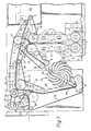
- the banknote dispensing apparatus shown in Figure 1 comprises a conventional detection module 1 to which banknotes are fed from cassettes (not shown) by conveying means (not shown).
- the module 1 includes a pair of rollers 2, driven via a drive gear 3 by a motor (not shown), between which the banknotes pass and the separation of which is monitored. If the separation between the two rollers 2 exceeds a threshold indicating the passage of overlapping or folded notes, an output signal is generated by the module 1.
- Banknotes are guided from the module 1 between a pair of guides 4 under the action of rollers 5 driven via the gear 3 to a diverting station 6.
- the diverting station 6 comprises a belt 7 mounted around rollers 8, 9; a belt 10 mounted around rollers 11, 12; and a guide member 13.
- the guide member 13 is pivotally mounted at 14 to a housing part of the apparatus (not shown).
- the guide member 13 has a first curved guide surface 15 facing the roller 8 and a second planar guide surface 16 facing the roller 12. In the position shown by dashed lines in Figure 1, the guide member 13 is arranged so that notes which reach the diverting station 6 from the module 1 are guided around the roller 8 and between the belt 7 and a belt 17 mounted about rollers 18, 19.
- the guide member 13 will be caused to pivot to the position shown in solid lines in Figure 1 in which the guide surface 15 engages the belt 7 and thus the unsuitable banknotes will be guided around the roller 12 and between the belt 10 and a belt 20 mounted around rollers 21, 22. These unsuitable notes will be fed by the belts 10, 20 to a dump cassette 23 which is partially illustrated in Figure 1.
- Banknotes that are suitable are fed by the belts 7, 17 to a conventional rotatable member comprising three conventional stacking wheels 24 having curved radially outwardly extending tines 25 defining sheet receiving slots.
- the stacking wheels 24 rotate in an anticlockwise direction and carry notes around the wheels into engagement with belts 26 ( Figure 2) mounted around rollers 27.
- the engagement of each note with the belts 26 causes the note to be stripped from the stacking wheels 24 and to be stacked in a stack 28 resting against a belt 29 which is stationary at this time.
- the belt 29 is mounted around rollers 30.
- the belts 26 When the notes have been stacked in the stack 28, the belts 26 are pivoted in anti-clockwise direction into the position shown at 26', in which the stack 28 is urged against the belt 29. If the number of banknotes in the stack 28 is correct, the belts 26, 29 are rotated to dispense the stack 28 between belts 31, 32 to a dispense outlet 33. (The belt 31 is entrained about rollers 34 while the belt 32 is entrained about rollers 35.)
- a guide member 36 is pivotally mounted to the apparatus and has a curved guide surface 37 facing the adjacent roller 30. In the position shown in Figure 1, the guide member 36 guides the stack of sheets to the dispense outlet 33. If the user decides he does not wish to receive the stack of sheets or detection apparatus has detected that the stack of sheets is unsuitable for some reason, the guide member 36 is pivoted so that the guide surface 37 engages the belt 29 and the stack of sheets 28 instead will be guided between a further guide surface 38 and the drive belt 31, between the belt 31 and a further belt 39 to a feed path defined between a pair of guide surfaces 40. The belt 39 is entrained about rollers 41. The stack of sheets 28 is moved between the guide surfaces 40 since it will be sandwiched between a pair of belts 42, 43.
- the stack of notes 28 will be passed from the guide surfaces 40 between the belt 43 and a belt 44 to the diverting station 6 where it will then pass to the dump cassette 23 between the belts 10, 20. In this way, part of the reject path for the stack of sheets 28 is the same as the reject path for the unsuitable sheets fed from the module 1.
- One of the rollers 41 is driven via a drive belt 60 from a toothed gear 61.
- the gear 61 engages a toothed gear 62 non-rotatably connected to one of the rollers 35.
- the gear 61 is driven by a motor (not shown).
- the apparatus will be controlled by a conventional microprocessor which is responsive to output signals from the module 1 and to input signals by a user to control the feeding of notes to the stack 28.
- the apparatus may further comprise means for counting the notes in the stack 28 and if a number of notes is incorrect then the stack may automatically be fed to the dump cassette 23.
- the stack 28 may be rejected at the command of a user.
- Each of the belts and the stacking wheels may be driven by a conventional motor (not shown) under the control of the microprocessor.
- the position of each guide member 13, 36 is also under the control of the microprocessor.
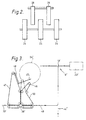
- FIG 3 illustrates a second example of banknote dispensing apparatus.
- the drawing is mainly schematic and it should be understood that the feed paths shown can be constructed in practice by using sets of endless belts in a similar way to that shown in Figure 1.
- banknotes are fed through a detection module (not shown) similar to the module 1 shown in Figure 1 along a feed path 44' to a diverting station 6'.
- the diverting station 6' includes a guide member 13' which is operable under the control of a microprocessor to guide the sheets either to stacking wheels 24' or a dump cassette 23'.
- the stacking wheels 24' are rotatable in an anti-clockwise direction.
- a stripper plate 45 extends between the stacking wheels 24' and notes carried in the stacking wheels 24' are stripped off the stacking wheel by the stripper plate 45 to form a stack 48.
- pivoting pinch rollers 46 are pivoted in an anti-clockwise direction to urge the stack of sheets against support belts 47 (shown in phantom in Figure 3).
- the stripper plate 45 is pivoted away from the stack 48.
- a guide member 36' is then moved to a suitable position for guiding the stack of notes 48 either to a dispense outlet 33' or to a dump feed path 49.
- the belts 47 and belts 50 together with other belts (not shown) making up the feed path are then rotated (probably at a speed reduced from that for feeding notes to the stack) and the stack of notes 48 is then fed either to the dispense outlet 33' or along the feed path 49 to the guide member 13' which is arranged to direct the stack of notes to the dump cassette 23'.
- If the stack of notes is fed to the dispense outlet 33' its final position can be controlled by a photosensor or by measured transport movement.
Landscapes
- Engineering & Computer Science (AREA)
- Mechanical Engineering (AREA)
- Pile Receivers (AREA)
- Separation, Sorting, Adjustment, Or Bending Of Sheets To Be Conveyed (AREA)
- Delivering By Means Of Belts And Rollers (AREA)
- Discharge By Other Means (AREA)
Claims (8)
Applications Claiming Priority (2)
| Application Number | Priority Date | Filing Date | Title |
|---|---|---|---|
| GB8406374 | 1984-03-12 | ||
| GB848406374A GB8406374D0 (en) | 1984-03-12 | 1984-03-12 | Sheet dispensing apparatus |
Publications (4)
| Publication Number | Publication Date |
|---|---|
| EP0155174A2 EP0155174A2 (fr) | 1985-09-18 |
| EP0155174A3 EP0155174A3 (en) | 1986-07-30 |
| EP0155174B1 true EP0155174B1 (fr) | 1989-02-22 |
| EP0155174B2 EP0155174B2 (fr) | 1991-10-30 |
Family
ID=10557920
Family Applications (1)
| Application Number | Title | Priority Date | Filing Date |
|---|---|---|---|
| EP85301684A Expired EP0155174B2 (fr) | 1984-03-12 | 1985-03-12 | Distributeur de feuille |
Country Status (5)
| Country | Link |
|---|---|
| US (1) | US4709820A (fr) |
| EP (1) | EP0155174B2 (fr) |
| JP (1) | JPS612651A (fr) |
| DE (1) | DE3568320D1 (fr) |
| GB (1) | GB8406374D0 (fr) |
Families Citing this family (14)
| Publication number | Priority date | Publication date | Assignee | Title |
|---|---|---|---|---|
| EP0334309B1 (fr) * | 1988-03-24 | 1995-07-12 | Kabushiki Kaisha Nippon Conlux | Appareil de distribution de papier imprimé et méthode pour sa commande |
| US4925179A (en) * | 1988-06-01 | 1990-05-15 | Harris Graphics Corporation | Delivery fan with undulated fan pockets |
| GB8825756D0 (en) * | 1988-11-03 | 1988-12-07 | Ncr Co | Sheet handling apparatus |
| JPH05262312A (ja) * | 1991-06-04 | 1993-10-12 | Ncr Corp | 用紙取り扱い装置 |
| US5131646A (en) * | 1991-08-19 | 1992-07-21 | Rockwell International Corporation | Printing press with movable fly |
| US5430664A (en) * | 1992-07-14 | 1995-07-04 | Technitrol, Inc. | Document counting and batching apparatus with counterfeit detection |
| GB9707243D0 (en) * | 1997-04-09 | 1997-05-28 | Ncr Int Inc | Self-service deposit method and apparatus |
| US6170818B1 (en) * | 1997-11-28 | 2001-01-09 | Diebold, Incorporated | Currency recycling automated banking machine media gate |
| RU2149817C1 (ru) * | 1999-04-07 | 2000-05-27 | Открытое акционерное общество "Чебоксарский приборостроительный завод "ЭЛАРА" | Устройство для выдачи листов |
| RU2191737C2 (ru) * | 2000-12-22 | 2002-10-27 | Открытое акционерное общество "Чебоксарский приборостроительный завод "ЭЛАРА" | Устройство для выдачи листов |
| DE10347767B4 (de) * | 2003-10-14 | 2006-03-09 | Wincor Nixdorf International Gmbh | Transportvorrichtung mit Verzweigung zum Transport von Blättern |
| DE10355637A1 (de) * | 2003-11-28 | 2005-06-30 | Wincor Nixdorf International Gmbh | Geldausgabeautomat |
| KR101016245B1 (ko) * | 2005-04-27 | 2011-05-18 | 노틸러스효성 주식회사 | 금융자동화기기의 출금장치 |
| JP5438093B2 (ja) * | 2009-02-27 | 2014-03-12 | グローリー株式会社 | 紙幣分類結束処理装置 |
Family Cites Families (12)
| Publication number | Priority date | Publication date | Assignee | Title |
|---|---|---|---|---|
| SE7711413L (sv) * | 1977-10-11 | 1979-04-12 | Lundblad Leif | Anordning for utmatning av blad fran ett forrad av blad till en uttagsoppning |
| GB2059391B (en) * | 1979-09-25 | 1983-06-22 | Laurel Bank Machine Co | Stacking paper sheets bank notes in dispensers |
| JPS57106996A (en) * | 1980-12-24 | 1982-07-03 | Tokyo Shibaura Electric Co | Currency automatic dealing device |
| US4479049A (en) * | 1981-01-22 | 1984-10-23 | Tokyo Shibaura Denki Kabushiki Kaisha | Automatic bank note transaction apparatus |
| DE3216830C2 (de) * | 1981-05-09 | 1985-11-07 | Laurel Bank Machines Co., Ltd., Tokio/Tokyo | Banknoten-Ein/Ausgabe-Vorrichtung |
| JPS5810265A (ja) * | 1981-07-10 | 1983-01-20 | Toshiba Corp | 通貨自動取引装置 |
| JPS5839391A (ja) * | 1981-08-31 | 1983-03-08 | ロ−レルバンクマシン株式会社 | 自動入出金機における入出金機構 |
| GB2111951A (en) * | 1981-11-13 | 1983-07-13 | De La Rue Syst | Sheet delivery mechanisms |
| US4482057A (en) * | 1981-12-30 | 1984-11-13 | Ncr Corporation | Record media dispensing apparatus |
| JPS5911490A (ja) * | 1982-07-12 | 1984-01-21 | 株式会社東芝 | 入出金装置 |
| JPS59136886A (ja) * | 1983-01-26 | 1984-08-06 | 株式会社東芝 | 自動取引装置 |
| JPS59205694A (ja) * | 1983-05-09 | 1984-11-21 | 株式会社東芝 | 紙葉類取出装置 |
-
1984
- 1984-03-12 GB GB848406374A patent/GB8406374D0/en active Pending
-
1985
- 1985-03-11 JP JP60046695A patent/JPS612651A/ja active Pending
- 1985-03-12 EP EP85301684A patent/EP0155174B2/fr not_active Expired
- 1985-03-12 US US06/710,964 patent/US4709820A/en not_active Expired - Fee Related
- 1985-03-12 DE DE8585301684T patent/DE3568320D1/de not_active Expired
Also Published As
| Publication number | Publication date |
|---|---|
| EP0155174B2 (fr) | 1991-10-30 |
| US4709820A (en) | 1987-12-01 |
| DE3568320D1 (en) | 1989-03-30 |
| EP0155174A3 (en) | 1986-07-30 |
| JPS612651A (ja) | 1986-01-08 |
| GB8406374D0 (en) | 1984-04-18 |
| EP0155174A2 (fr) | 1985-09-18 |
Similar Documents
| Publication | Publication Date | Title |
|---|---|---|
| EP0155174B1 (fr) | Distributeur de feuille | |
| CA1310023C (fr) | Appareil de manutention de feuilles | |
| US4684119A (en) | Sheet feeding apparatus | |
| EP0616963B1 (fr) | Appareil de manipulation de feuilles | |
| US4733765A (en) | Cash handling machine for handling mixtures of notes and coins introduced together | |
| JP3336210B2 (ja) | 紙幣処理機 | |
| JPS6211392B2 (fr) | ||
| JP3284040B2 (ja) | 紙幣処理機 | |
| US4712785A (en) | Sheet stacking apparatus | |
| EP0367519A2 (fr) | Appareil de manipulation de feuilles | |
| JP3197810B2 (ja) | 紙幣処理機 | |
| EP0194139A2 (fr) | Regroupement de feuilles en une pile | |
| JPH0517062A (ja) | 紙片の搬送スタツク装置 | |
| US4772005A (en) | Sheet feeding apparatus | |
| GB2198122A (en) | Sheet store loading apparatus | |
| US4877232A (en) | Paper discharge apparatus | |
| US20120242031A1 (en) | Paper-sheet handling apparatus and paper-sheet handling method | |
| US5569015A (en) | Intermediate storage apparatus | |
| JPS61273449A (ja) | 自動入出金機 | |
| EP1760018B1 (fr) | Appareil d'empilage pour feuilles de papier | |
| GB2213472A (en) | Sheet feeding apparatus | |
| JP3267697B2 (ja) | 硬貨処理機 | |
| WO2014002117A1 (fr) | Système et procédé de collecte et de présentation de billets | |
| JP3234156B2 (ja) | 紙幣処理機 | |
| JP3488005B2 (ja) | 紙幣処理機 |
Legal Events
| Date | Code | Title | Description |
|---|---|---|---|
| PUAI | Public reference made under article 153(3) epc to a published international application that has entered the european phase |
Free format text: ORIGINAL CODE: 0009012 |
|
| AK | Designated contracting states |
Designated state(s): CH DE FR GB IT LI SE |
|
| PUAL | Search report despatched |
Free format text: ORIGINAL CODE: 0009013 |
|
| AK | Designated contracting states |
Kind code of ref document: A3 Designated state(s): CH DE FR GB IT LI SE |
|
| 17P | Request for examination filed |
Effective date: 19870122 |
|
| 17Q | First examination report despatched |
Effective date: 19871109 |
|
| GRAA | (expected) grant |
Free format text: ORIGINAL CODE: 0009210 |
|
| AK | Designated contracting states |
Kind code of ref document: B1 Designated state(s): CH DE FR GB IT LI SE |
|
| REF | Corresponds to: |
Ref document number: 3568320 Country of ref document: DE Date of ref document: 19890330 |
|
| ET | Fr: translation filed | ||
| ITTA | It: last paid annual fee | ||
| PGFP | Annual fee paid to national office [announced via postgrant information from national office to epo] |
Ref country code: FR Payment date: 19890331 Year of fee payment: 5 |
|
| PGFP | Annual fee paid to national office [announced via postgrant information from national office to epo] |
Ref country code: CH Payment date: 19890412 Year of fee payment: 5 |
|
| ITF | It: translation for a ep patent filed | ||
| PLBI | Opposition filed |
Free format text: ORIGINAL CODE: 0009260 |
|
| 26 | Opposition filed |
Opponent name: LENNART SJOEOE Effective date: 19890619 |
|
| PGFP | Annual fee paid to national office [announced via postgrant information from national office to epo] |
Ref country code: SE Payment date: 19900314 Year of fee payment: 6 |
|
| PG25 | Lapsed in a contracting state [announced via postgrant information from national office to epo] |
Ref country code: LI Effective date: 19900331 Ref country code: CH Effective date: 19900331 |
|
| PG25 | Lapsed in a contracting state [announced via postgrant information from national office to epo] |
Ref country code: FR Effective date: 19901130 |
|
| REG | Reference to a national code |
Ref country code: CH Ref legal event code: PL |
|
| REG | Reference to a national code |
Ref country code: FR Ref legal event code: ST |
|
| PG25 | Lapsed in a contracting state [announced via postgrant information from national office to epo] |
Ref country code: SE Effective date: 19910313 |
|
| PUAH | Patent maintained in amended form |
Free format text: ORIGINAL CODE: 0009272 |
|
| STAA | Information on the status of an ep patent application or granted ep patent |
Free format text: STATUS: PATENT MAINTAINED AS AMENDED |
|
| 27A | Patent maintained in amended form |
Effective date: 19911030 |
|
| AK | Designated contracting states |
Kind code of ref document: B2 Designated state(s): CH DE FR GB IT LI SE |
|
| EN3 | Fr: translation not filed ** decision concerning opposition | ||
| EUG | Se: european patent has lapsed |
Ref document number: 85301684.8 Effective date: 19911009 |
|
| PGFP | Annual fee paid to national office [announced via postgrant information from national office to epo] |
Ref country code: GB Payment date: 19950302 Year of fee payment: 11 |
|
| PGFP | Annual fee paid to national office [announced via postgrant information from national office to epo] |
Ref country code: DE Payment date: 19950309 Year of fee payment: 11 |
|
| PG25 | Lapsed in a contracting state [announced via postgrant information from national office to epo] |
Ref country code: GB Effective date: 19960312 |
|
| GBPC | Gb: european patent ceased through non-payment of renewal fee |
Effective date: 19960312 |
|
| PG25 | Lapsed in a contracting state [announced via postgrant information from national office to epo] |
Ref country code: DE Effective date: 19961203 |
|
| REG | Reference to a national code |
Ref country code: CH Ref legal event code: AEN Free format text: MAINTIEN DU BREVET DONT L'ETENDUE A ETE MODIFIEE |