EP0155207A1 - Verfahren und Anlage zur Destillation mit Hilfe von aufeinanderfolgenden Trennungen - Google Patents
Verfahren und Anlage zur Destillation mit Hilfe von aufeinanderfolgenden Trennungen Download PDFInfo
- Publication number
- EP0155207A1 EP0155207A1 EP85400300A EP85400300A EP0155207A1 EP 0155207 A1 EP0155207 A1 EP 0155207A1 EP 85400300 A EP85400300 A EP 85400300A EP 85400300 A EP85400300 A EP 85400300A EP 0155207 A1 EP0155207 A1 EP 0155207A1
- Authority
- EP
- European Patent Office
- Prior art keywords
- column
- series
- columns
- residue
- gasoline
- Prior art date
- Legal status (The legal status is an assumption and is not a legal conclusion. Google has not performed a legal analysis and makes no representation as to the accuracy of the status listed.)
- Granted
Links
Images




Classifications
-
- C—CHEMISTRY; METALLURGY
- C10—PETROLEUM, GAS OR COKE INDUSTRIES; TECHNICAL GASES CONTAINING CARBON MONOXIDE; FUELS; LUBRICANTS; PEAT
- C10G—CRACKING HYDROCARBON OILS; PRODUCTION OF LIQUID HYDROCARBON MIXTURES, e.g. BY DESTRUCTIVE HYDROGENATION, OLIGOMERISATION, POLYMERISATION; RECOVERY OF HYDROCARBON OILS FROM OIL-SHALE, OIL-SAND, OR GASES; REFINING MIXTURES MAINLY CONSISTING OF HYDROCARBONS; REFORMING OF NAPHTHA; MINERAL WAXES
- C10G7/00—Distillation of hydrocarbon oils
Definitions
- the present invention relates to a process for the distillation of petroleum or synthetic origin oil by progressive separation, in which the charge preheated by heat exchange is prefractionated in successive phases in at least one column operating at a pressure of between 1 and 5 bar abs ., as well as an installation for implementing the method.
- Such processes are known using recovery heat to save energy and effecting a prior separation of varying degrees from light fractions, such as light petroleum gases, gasolines and kerosene before atmospheric distillation.
- the feed residue from these columns is necessarily reheated in one or more fuel ovens before undergoing distillation in these columns.
- the object of the process according to the present invention is to provide improvements to the abovementioned processes by carrying out a more gradual separation of petroleum fractions before and after atmospheric distillation to allow better use of heating by means of recovery heat.
- the idea which is the basis of the invention lies in the observation that by proceeding by a succession of progressive separations accomplished in a series of columns of relatively reduced volume, one arrives at a better use of the heat of recovery, thanks to the measured and judiciously distributed heat gains.
- the process according to the invention is characterized in that successively at the head of several columns of a first series of distillation columns, each of which is fed with a residue from the previous column, more and more petroleum fractions heavy and a so-called atmospheric residue is collected at the bottom of the last column of this series, which is then treated in a vacuum distillation zone comprising reheating of the charge in an oven.
- the atmospheric residue collected at the bottom of the last column of the first series is reheated in an oven, then treated in a vacuum distillation column.
- said residue feeds, without external heat input, a first vacuum distillation column, the residue of which, after reheating in an oven, is treated in a second vacuum distillation column.
- each section collected at the head of each column of the first series individually feeds a column of a second series of columns, the distillates of which are common petroleum products.
- the method according to the invention allows great flexibility of operation according to the production criteria set.
- a grouping of two columns of the second series will be carried out, either by superimposing them for example in a single column of fractionation of essences with lateral withdrawal, or by regrouping the two columns placed downstream of the column of fractionation of essences and producing heavy gasoline and kerosene.
- an additional column can be done according to other production criteria. For example, in the case where the production of a solvent is required lying between heavy gasoline and kerosene, one could insert an additional column before the last column of the first series supplying an additional column placed before the last column from the second series.
- a first of the columns of the second series is a column for stabilizing gasolines whose volatile effluent feeds a fractionation installation of light petroleum gases, the residue of which joins the gasoline cut from the second column of the first series to supply a second column of the second series.
- a second column of the second series is a column for fractionating gasolines, the residue of which consists of a heavy gasoline which joins the volatile fraction of a third column of the second series.
- the residue from the gasoline fractionation column feeds the next column of the same series.
- the initial charge, the residues circulating between the columns of the first series and the effluents circulating between the columns of the second series are preferably preheated by exchange of sensible and latent heat ceded by other effluents,
- the supply of heat for reboiling columns is advantageously effected by heat exchange of the same kind.
- part of this addition can be carried out by exchange with a fraction of the residue from the last vacuum distillation column which is permanently recycled to the furnace feed.
- the invention also relates to an installation for the implementation of the above method, characterized in that four columns of the first series of columns are connected by their head outputs individually to the four columns of the second series of columns, the first is a gasoline stabilization column connected by a head outlet to a light petroleum gas fractionation plant and by a bottom outlet to a second column which is a gasoline fractionation column connected by the head and gas outlet melts in essebces storage tanks, the third column being a heavy gasoline and kerosene separation column connected to storage tanks and the fourth column being supplied by the top fraction of the last column called atmospheric from the first .series of columns being also connected to the storage tanks, in that the last atmospheric column of the first series is a reflux column connected to a stripper connected to a so-called atmospheric diesel storage tank and which is provided with a bottom outlet for the so-called atmospheric residue connected through a fuel-heated oven to the supply of a distillation column vacuum connected to storage tanks.
- the so-called atmospheric column is connected by a bottom outlet to a first vacuum distillation column provided with lateral withdrawal means and a bottom outlet connected through the furnace to a second distillation column under vacuum, the two vacuum distillation columns being connected by means of lateral withdrawal to diesel and distillate storage tanks.
- an additional column is inserted between the second and the third column of the first series, the
- .head outlet feeds an additional column interposed between the second and third column of the second series, possibly supplied by the bottom outlet of the second column of the second series, and whose head outlet is connected to a storage tank average gasoline.
- an additional column is interposed between the third and the fourth column of the first series whose head outlet feeds an additional column interposed between the third and fourth column of the second series whose head outlet is connected to a solvent storage tank, the boiling point of which is between that of heavy petrol and that of kerosene.
- the second and third columns of the second series are superimposed columns in a single gasoline fractionation tower supplying via the bottom outlet a fourth column of the second series, each column being connected to respective storage tanks.
- the third and fourth column of the second series are grouped together in a single column, the power supplies of which are connected to the head outputs of the third and the fourth column of the first series.
- the supply of the third column of the second series which is a separation column for heavy petrol and kerosene, is connected to the bottom outlet of the column which precedes it in the same series and at the exit of the third column of the first series.
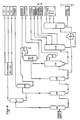
- the installation includes two series of columns.
- the bottom of the last column C10, called the atmospheric column, supplies atmospheric residue to a first vacuum distillation column C12, the residue of which is preheated in a single fuel oven is introduced into a second vacuum distillation column C13.
- the columns of the first series of columns are distillation columns with trays for the separation of the top and bottom fractions and their operating conditions are adjusted, with regard to temperature and pressure, so that the volatile fractions released are of more heavy pus.
- the volatile fraction of column C01 composed of all of the light petroleum gases and part of the gasoline supplies column C07 of the second series which is a gasoline stabilization column, the volatile fraction of which supplies a fractionation installation of light petroleum gases.
- the volatile fraction from column C02 joins the residue from column C07 and supplies gasoline alone to column C04, which is a column for fractionating gasolines, the top effluent of which is a light gasoline and the residue of which is a heavy gasoline.
- the volatile fraction of column C03 composed of a remainder of gasoline and kerosene feeds column C05 which extracts heavy gasoline therefrom as volatile fraction and kerosene as residue.
- the last column C10 of the first series is an atmospheric reflux column whose bottom is stripped with water vapor. A C11 stripper is connected to the upper part of the column.
- the volatile fraction from column C10 supplies column C06 with an effluent containing gasoline, kerosene and water.
- the residue from column C06 is kerosene, which joins the residue from column C05 to be stored.
- the volatile fraction after separation of the water, constitutes the - the remainder of the heavy gasoline which is sent to storage.
- the stripper C11 of the column C10 makes it possible to rid the light atmospheric diesel of the volatile fractions before shipment to storage.
- the atmospheric residue stripped with water vapor at the bottom of column C10 is introduced into a first vacuum distillation column C12, where three volatile fractions are drawn off laterally at different column levels: heavy diesel, vacuum diesel and a vacuum distillate, as well as a residue.
- the residue from column C12 is heated in an oven supplied with fuel, then introduced into a second vacuum distillation column C13, which separates several cups of distillates under vacuum, as well as a residue under vacuum.
- the crude is desalted in a two-stage desalter, B08, B09 , then heated under pressure to 157 ° C (F2) in the exchangers E15 (low pressure steam), E16 (vacuum distillates, F3.2) and E17 (atmospheric diesel) it supplies column C01 at 2 bar abs.
- the reflux is pumped from the reflux flask B01 using the pump P04 and returned to the top of the column C01.
- the liquid, F7 is taken up by the pump P05, then heated under pressure to 247 ° C using the following exchangers: E25 (reflux circulating vacuum distillate, F27), E26 (reflux circulating vacuum diesel), E27 (reflux circulating vacuum distillate), E28 (condenser from column C03), E29 (vacuum distillate, F29), E30 (vacuum residue, F33), E31 (circulating reflux under atmospheric diesel, F13), E32 (vacuum residue), E33 (reflux circulating under atmospheric diesel), E34 (circulating supply reflux from column C12, F17), E35 (reflux circulating from distillate under vacuum) and E36 (reflux circulating under atmospheric diesel).
- This flow feeds the column C02 at 1.95 bars abs.
- This column produces a steam distillate, F8, at 141 ° C consisting of a gasoline cup.
- the reflux of this column is provided by the exchanger E52 (very low pressure steam generator), the tank 802 and the pump P07.
- the bottom of the column, F11 is taken up by the pump P08, heated to 320 ° C in the exchanger E42 (vacuum residue), then mixed with 100 t / h of vacuum residue at 380 ° C, F12, in order to to supply column C10 at 2.3 bar abs.
- the bottom of this column is stripped by 7.5 t / h of low pressure steam.
- This column is provided with a reflux circulating under withdrawal of the diesel fuel, F13, which condenses the internal reflux necessary for the proper functioning of the column.
- a side stripper C11 makes it possible to obtain 59 t / h of atmospheric diesel, F14, consisting of a cut of heavy fuel, kerosene and water vapor.
- the exchanger E19, the balloon B10 and the pump P09 ensure the reflux of the column. This reflux ensures the fractionation between the kerosene and diesel cuts.
- the diesel fuel produced is cooled to 45 ° C in exchangers E17, E14, E07 and E59 (cooling water).
- This column produces 80 t / h of atmospheric diesel, F21, whose cooling to 45 ° C is ensured by the exchanger E60 (cooling water), 38 t / h of vacuum diesel, F22, cooled to 45 ° C in exchangers E08, E55 (oven air preheater) and 24 t / h of vacuum distillate, F23, from which the heat available up to 160 ° C is recovered in exchanger E18.
- the column is vacuumed by a pre-condenser and a group of ejectors common with column C13.
- the process water is taken from the tank B11 by the pump P25 and sent to a water treatment installation.
- the heat recovery up to 160 ° C contained in these flows takes place in the exchanger E16, the vacuum distillate No. 4 having been previously cooled in the exchanger E29.
- the bottom of the column is stripped using 9 t / h of very low pressure steam.
- the vacuum residue produced at the bottom of the tower is taken up by the pump P26, part of this residue under hot vacuum is recycled upstream of the column C10.
- the vacuum residue is successively cooled to 230 ° C in the exchangers E42, E40, E38, E46 (heating of the column C05), E37, E32 and E30. Part of this residue, after the E42 exchanger, is recycled at the bottom of the tower, in order to adjust the temperature, F34.
- the vacuuming of this column is ensured by a pre-condenser and an ejector-condenser system common to column C12.
- the steam distillate (F4) from column C01 is cooled to 40 ° C in the exchanger E61 (cooling water).
- the liquid and vapor phases obtained are separated in balloon B12.
- the vapor phase is heated to 60 ° C, F35, in the exchanger E50 (heavy petrol) before being compressed to 4 bar abs. using compressor K01 to supply column C07.
- the liquid phase is taken up by the pump P31, heated to 80 ° C in the exchanger E51 (heavy petrol) before feeding the column C07, F36.
- Reboiling of the column C05 is ensured by the exchanger E46.
- the condensation of the reflux and the distillate takes place in the exchanger E10 and the flask B05.
- the P05 pump ensures the reflux at the head of the column and the shipment of heavy fuel.
- the pump P12 takes up the kerosene produced at the bottom and this is cooled to 40 ° C., mixed with the 45 t / h of kerosene produced at the bottom of the column C06, F43, in the following exchangers: E43, E12, E48 and E49 (heat input to the light gas treatment section), E58 (cooling water).
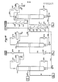
- the first vacuum distillation column C12 (FIG. 2) can be omitted and the atmospheric residue from the atmospheric column C10, passing through the oven, passed through the second vacuum distillation column C13, including the effluents contain both heavy and vacuum gas oils, as well as distillates.
- columns C04 and C05 are grouped together in a single fractionation tower for gasolines and kerosene with lateral withdrawal, supplied by the effluents from columns C02 and C03 of the first series of columns.
- an additional column C04 'and an additional column C02' were inserted respectively in the second and the first series of columns.
- This diagram applies particularly, when one wants to favor the production of the average gasoline.
- Column C04 ' is fed by the residue from column C04 and by volatile effluents from column C02'.
- the column C05 separating the heavy gasoline from the kerosene is fed by the volatile effluents from the column C03 and by the residue from the column C04.
Landscapes
- Chemical & Material Sciences (AREA)
- Oil, Petroleum & Natural Gas (AREA)
- Engineering & Computer Science (AREA)
- Chemical Kinetics & Catalysis (AREA)
- General Chemical & Material Sciences (AREA)
- Organic Chemistry (AREA)
- Production Of Liquid Hydrocarbon Mixture For Refining Petroleum (AREA)
- Vaporization, Distillation, Condensation, Sublimation, And Cold Traps (AREA)
Priority Applications (1)
| Application Number | Priority Date | Filing Date | Title |
|---|---|---|---|
| AT85400300T ATE28660T1 (de) | 1984-02-24 | 1985-02-20 | Verfahren und anlage zur destillation mit hilfe von aufeinanderfolgenden trennungen. |
Applications Claiming Priority (2)
| Application Number | Priority Date | Filing Date | Title |
|---|---|---|---|
| FR8402806 | 1984-02-24 | ||
| FR8402806A FR2560204A1 (fr) | 1984-02-24 | 1984-02-24 | Procede et installation de distillation de petrole par separations progressives |
Publications (2)
| Publication Number | Publication Date |
|---|---|
| EP0155207A1 true EP0155207A1 (de) | 1985-09-18 |
| EP0155207B1 EP0155207B1 (de) | 1987-07-29 |
Family
ID=9301348
Family Applications (1)
| Application Number | Title | Priority Date | Filing Date |
|---|---|---|---|
| EP85400300A Expired EP0155207B1 (de) | 1984-02-24 | 1985-02-20 | Verfahren und Anlage zur Destillation mit Hilfe von aufeinanderfolgenden Trennungen |
Country Status (10)
| Country | Link |
|---|---|
| US (1) | US4664785A (de) |
| EP (1) | EP0155207B1 (de) |
| JP (1) | JPS60210695A (de) |
| AT (1) | ATE28660T1 (de) |
| AU (1) | AU568722B2 (de) |
| CA (1) | CA1250244A (de) |
| DE (1) | DE3560403D1 (de) |
| FR (1) | FR2560204A1 (de) |
| IN (1) | IN163181B (de) |
| NO (1) | NO167043C (de) |
Cited By (1)
| Publication number | Priority date | Publication date | Assignee | Title |
|---|---|---|---|---|
| RU2224004C1 (ru) * | 2002-08-01 | 2004-02-20 | Коломыцев Владимир Николаевич | Устройство для получения углеводородных продуктов |
Families Citing this family (13)
| Publication number | Priority date | Publication date | Assignee | Title |
|---|---|---|---|---|
| FR2594349B1 (fr) * | 1986-02-18 | 1989-11-17 | Elf Aquitaine | Colonne de distillation a circulation helicoidale de liquide avec espacement dissymetrique des plateaux |
| RU2100403C1 (ru) * | 1996-05-12 | 1997-12-27 | Валерий Георгиевич Леонтьевский | Способ фракционирования нефти и установка для его осуществления |
| JP4495791B2 (ja) * | 1998-07-03 | 2010-07-07 | 日揮株式会社 | コンバインドサイクル発電システム |
| WO2001042393A1 (fr) * | 1998-08-03 | 2001-06-14 | Jgc Corporation | Procede et dispositif de traitement du petrole |
| RU2145971C1 (ru) * | 1998-12-15 | 2000-02-27 | Леонтьевский Валерий Георгиевич | Способ поточной перегонки мазута и устройство для его осуществления |
| KR100326588B1 (ko) * | 1998-12-28 | 2002-10-12 | 에스케이 주식회사 | 근적외선분광분석기술을활용한자동원유분석방법 |
| FR2791133B1 (fr) * | 1999-03-19 | 2001-10-12 | Multidyn | Procede et dispositif de mesure d'un couple exerce sur une piece soumise a des efforts de couple et de flexion |
| RU2159792C1 (ru) * | 1999-03-29 | 2000-11-27 | Предприятие "Астраханьгазпром" РАО "Газпром" | Способ разделения газового конденсата |
| RU2191800C2 (ru) * | 2000-01-05 | 2002-10-27 | Общество с ограниченной ответственностью "Интербизнеспроект" | Способ первичной перегонки углеводородного сырья (газового конденсата и нефти) |
| RU2211853C2 (ru) * | 2001-07-23 | 2003-09-10 | Общество с ограниченной ответственностью "Интербизнеспроект" | Атмосферно-вакуумная установка получения топливных фракций из углеводородного сырья |
| DE10356245B4 (de) * | 2003-12-02 | 2007-01-25 | Alphakat Gmbh | Verfahren zur Erzeugung von Dieselöl aus kohlenwasserstoffhaltigen Reststoffen sowie eine Vorrichtung zur Durchführung dieses Verfahrens |
| US20120168352A1 (en) * | 2010-12-30 | 2012-07-05 | Kellogg Brown & Root Llc | Systems and methods for processing hydrocarbon feedstocks |
| US9677006B2 (en) | 2013-06-24 | 2017-06-13 | Fluor Technologies Corporation | Multiple preflash and exchanger (MPEX) network system for crude and vacuum units |
Citations (3)
| Publication number | Priority date | Publication date | Assignee | Title |
|---|---|---|---|---|
| CH387207A (de) * | 1960-12-10 | 1965-01-31 | Inventa Ag | Verfahren zur Fraktionierung von Rohöl |
| US3968030A (en) * | 1974-01-17 | 1976-07-06 | Spie-Batignolles | Method and an installation for improving the energy balance of installations for processing chemical process streams and especially petroleum refineries |
| DE3205802A1 (de) * | 1982-02-18 | 1983-08-25 | Edeleanu Gmbh, 6000 Frankfurt | Verfahren zur atmosphaerischen fraktionierenden destillation von rohoelen |
Family Cites Families (10)
| Publication number | Priority date | Publication date | Assignee | Title |
|---|---|---|---|---|
| US1954839A (en) * | 1924-07-15 | 1934-04-17 | Phillips Petroleum Co | Rectifying process |
| US1735558A (en) * | 1924-07-15 | 1929-11-12 | Youker Malcolm Phillip | Rectifying process |
| US1780286A (en) * | 1927-07-01 | 1930-11-04 | Texas Co | Treating hydrocarbon oils |
| US1744599A (en) * | 1927-11-11 | 1930-01-21 | Texas Co | Treating hydrocarbon oil |
| US1997675A (en) * | 1930-08-28 | 1935-04-16 | Standard Oil Co | Distillation |
| US2904510A (en) * | 1956-07-10 | 1959-09-15 | Exxon Research Engineering Co | Process for treating catalytic cracking recycle fractions |
| US3320158A (en) * | 1964-11-06 | 1967-05-16 | Phillips Petroleum Co | Crude oil fractionation method |
| DE1768817B1 (de) * | 1968-07-03 | 1972-04-27 | Zieren Chemiebau Gmbh Dr A | Verfahren zur Reinigung von rohem Phthalsaeureanhydrid durch Destillation |
| US3567628A (en) * | 1968-10-25 | 1971-03-02 | Phillips Petroleum Co | Production of high flash point topped crude and high flash point asphalt |
| US4082653A (en) * | 1976-11-17 | 1978-04-04 | Degraff Richard Raymond | Crude oil distillation process |
-
1984
- 1984-02-24 FR FR8402806A patent/FR2560204A1/fr not_active Withdrawn
-
1985
- 1985-02-13 IN IN119/DEL/85A patent/IN163181B/en unknown
- 1985-02-20 AT AT85400300T patent/ATE28660T1/de not_active IP Right Cessation
- 1985-02-20 EP EP85400300A patent/EP0155207B1/de not_active Expired
- 1985-02-20 US US06/703,496 patent/US4664785A/en not_active Expired - Lifetime
- 1985-02-20 DE DE8585400300T patent/DE3560403D1/de not_active Expired
- 1985-02-21 AU AU39040/85A patent/AU568722B2/en not_active Expired
- 1985-02-22 CA CA000474935A patent/CA1250244A/fr not_active Expired
- 1985-02-22 JP JP60034278A patent/JPS60210695A/ja active Granted
- 1985-02-22 NO NO850736A patent/NO167043C/no not_active IP Right Cessation
Patent Citations (3)
| Publication number | Priority date | Publication date | Assignee | Title |
|---|---|---|---|---|
| CH387207A (de) * | 1960-12-10 | 1965-01-31 | Inventa Ag | Verfahren zur Fraktionierung von Rohöl |
| US3968030A (en) * | 1974-01-17 | 1976-07-06 | Spie-Batignolles | Method and an installation for improving the energy balance of installations for processing chemical process streams and especially petroleum refineries |
| DE3205802A1 (de) * | 1982-02-18 | 1983-08-25 | Edeleanu Gmbh, 6000 Frankfurt | Verfahren zur atmosphaerischen fraktionierenden destillation von rohoelen |
Non-Patent Citations (1)
| Title |
|---|
| CHEMICAL ENGINEERING PROGRESS, vol. 79, no. 7, juillet 1983, pages 33-38, New York, US; F. KLEINSCHRODT et al.: "Exchanger networks for crude units. Powerful computer programs now make it possible to simultaneously evaluate fractionator efficiency, flexibility, and energy usage" * |
Cited By (1)
| Publication number | Priority date | Publication date | Assignee | Title |
|---|---|---|---|---|
| RU2224004C1 (ru) * | 2002-08-01 | 2004-02-20 | Коломыцев Владимир Николаевич | Устройство для получения углеводородных продуктов |
Also Published As
| Publication number | Publication date |
|---|---|
| DE3560403D1 (en) | 1987-09-03 |
| ATE28660T1 (de) | 1987-08-15 |
| NO850736L (no) | 1985-08-26 |
| FR2560204A1 (fr) | 1985-08-30 |
| NO167043B (no) | 1991-06-17 |
| JPH0535200B2 (de) | 1993-05-25 |
| IN163181B (de) | 1988-08-20 |
| AU3904085A (en) | 1985-09-12 |
| EP0155207B1 (de) | 1987-07-29 |
| AU568722B2 (en) | 1988-01-07 |
| NO167043C (no) | 1991-09-25 |
| US4664785A (en) | 1987-05-12 |
| JPS60210695A (ja) | 1985-10-23 |
| CA1250244A (fr) | 1989-02-21 |
Similar Documents
| Publication | Publication Date | Title |
|---|---|---|
| EP0155207B1 (de) | Verfahren und Anlage zur Destillation mit Hilfe von aufeinanderfolgenden Trennungen | |
| US12404454B2 (en) | System and process for converting waste plastic into fuel | |
| US20070227874A1 (en) | Device and Method for Recovering Fractional Hydrocarbones from Recycled Plastic Fractions and/or Oily Residues | |
| ES2218871T3 (es) | Produccion de olefinas ligeras a partir de una corriente de hidrocarburo liquido contaminado por craqueo termico. | |
| US5527449A (en) | Conversion of waste oils, animal fats and vegetable oils | |
| CA2558347C (en) | Device and method for recovering fractional hydrocarbons from reclaimed plastic materials and/or from oily residues | |
| EP2978825A1 (de) | Verarbeitung von dieselkraftstoff aus altöl | |
| EP0576346B1 (de) | Verfahren zur Entwässerung von Lösungsmitteln von ein Kohlenwasserstoff Entwachsungsverfahren | |
| CN113698959A (zh) | 一种废矿物油回收处理工艺 | |
| CA2839997C (en) | System and method for processing diesel fuel from waste oil | |
| CA1085336A (en) | Multistage evaporator apparatus and method of distilling petroleum | |
| US3697387A (en) | Process and device for the purification of a mixture of organic substances of high molecular weight | |
| US6337011B1 (en) | Pour point depression unit using mild thermal cracker | |
| CN105038847A (zh) | 一种废机油提炼方法和提炼设备 | |
| NO170429B (no) | Fremgangsmaate ved raffinering av brukte smoereoljer og apparat til anvendelse ved fremgangsmaaten | |
| US6267848B1 (en) | Method for generating vacuum in mass-exchange columns | |
| FR2705103A1 (fr) | Procédé et installation pour le traitement par thermolyse sous vide de produits solides, avec séparation et récupération en continu d'une fraction liquide de ces produits. | |
| US11041126B2 (en) | Method, apparatus, and system for providing an integrated bioenergy complex to process mixed solid waste | |
| FR2549043A1 (fr) | Procede de fractionnement d'une solution aqueuse de butanol et d'acetone | |
| CN1656201A (zh) | 提纯过程和设备 | |
| US20130168291A1 (en) | Method, Apparatus and System for Hydrocarbon Recovery | |
| KR0182769B1 (ko) | 탱크 바닥 폐기물의 회수방법 | |
| JPH09279158A (ja) | 固液分離装置より排出されるカーボン残渣の処理方法 | |
| BE402927A (de) | ||
| WO2010119189A1 (fr) | Procede et installation de distillation de petrole reutilisant des energies de bas niveau thermique |
Legal Events
| Date | Code | Title | Description |
|---|---|---|---|
| PUAI | Public reference made under article 153(3) epc to a published international application that has entered the european phase |
Free format text: ORIGINAL CODE: 0009012 |
|
| 17P | Request for examination filed |
Effective date: 19850226 |
|
| AK | Designated contracting states |
Designated state(s): AT BE DE FR GB IT NL |
|
| 17Q | First examination report despatched |
Effective date: 19861106 |
|
| ITF | It: translation for a ep patent filed | ||
| GRAA | (expected) grant |
Free format text: ORIGINAL CODE: 0009210 |
|
| AK | Designated contracting states |
Kind code of ref document: B1 Designated state(s): AT BE DE FR GB IT NL |
|
| REF | Corresponds to: |
Ref document number: 28660 Country of ref document: AT Date of ref document: 19870815 Kind code of ref document: T |
|
| REF | Corresponds to: |
Ref document number: 3560403 Country of ref document: DE Date of ref document: 19870903 |
|
| PLBE | No opposition filed within time limit |
Free format text: ORIGINAL CODE: 0009261 |
|
| STAA | Information on the status of an ep patent application or granted ep patent |
Free format text: STATUS: NO OPPOSITION FILED WITHIN TIME LIMIT |
|
| 26N | No opposition filed | ||
| ITTA | It: last paid annual fee | ||
| REG | Reference to a national code |
Ref country code: GB Ref legal event code: IF02 |
|
| PGFP | Annual fee paid to national office [announced via postgrant information from national office to epo] |
Ref country code: AT Payment date: 20040122 Year of fee payment: 20 |
|
| PGFP | Annual fee paid to national office [announced via postgrant information from national office to epo] |
Ref country code: NL Payment date: 20040127 Year of fee payment: 20 |
|
| PGFP | Annual fee paid to national office [announced via postgrant information from national office to epo] |
Ref country code: GB Payment date: 20040128 Year of fee payment: 20 |
|
| PGFP | Annual fee paid to national office [announced via postgrant information from national office to epo] |
Ref country code: BE Payment date: 20040129 Year of fee payment: 20 |
|
| PGFP | Annual fee paid to national office [announced via postgrant information from national office to epo] |
Ref country code: DE Payment date: 20040212 Year of fee payment: 20 |
|
| PGFP | Annual fee paid to national office [announced via postgrant information from national office to epo] |
Ref country code: FR Payment date: 20040223 Year of fee payment: 20 |
|
| PG25 | Lapsed in a contracting state [announced via postgrant information from national office to epo] |
Ref country code: GB Free format text: LAPSE BECAUSE OF EXPIRATION OF PROTECTION Effective date: 20050219 |
|
| PG25 | Lapsed in a contracting state [announced via postgrant information from national office to epo] |
Ref country code: NL Free format text: LAPSE BECAUSE OF EXPIRATION OF PROTECTION Effective date: 20050220 |
|
| BE20 | Be: patent expired |
Owner name: SOC. NATIONALE *ELF AQUITAINE Effective date: 20050220 |
|
| REG | Reference to a national code |
Ref country code: GB Ref legal event code: PE20 |
|
| NLV7 | Nl: ceased due to reaching the maximum lifetime of a patent |
Effective date: 20050220 |
|
| BE20 | Be: patent expired |
Owner name: SOC. NATIONALE *ELF AQUITAINE Effective date: 20050220 |