EP0155213A1 - Bearbeitungsanlage mit Mehrprozessorenstruktur zur Steuerung und Kontrolle eines Verfahrens - Google Patents
Bearbeitungsanlage mit Mehrprozessorenstruktur zur Steuerung und Kontrolle eines Verfahrens Download PDFInfo
- Publication number
- EP0155213A1 EP0155213A1 EP85400404A EP85400404A EP0155213A1 EP 0155213 A1 EP0155213 A1 EP 0155213A1 EP 85400404 A EP85400404 A EP 85400404A EP 85400404 A EP85400404 A EP 85400404A EP 0155213 A1 EP0155213 A1 EP 0155213A1
- Authority
- EP
- European Patent Office
- Prior art keywords
- control
- state
- tbt
- control unit
- actuator
- Prior art date
- Legal status (The legal status is an assumption and is not a legal conclusion. Google has not performed a legal analysis and makes no representation as to the accuracy of the status listed.)
- Withdrawn
Links
Images


Classifications
-
- G—PHYSICS
- G05—CONTROLLING; REGULATING
- G05B—CONTROL OR REGULATING SYSTEMS IN GENERAL; FUNCTIONAL ELEMENTS OF SUCH SYSTEMS; MONITORING OR TESTING ARRANGEMENTS FOR SUCH SYSTEMS OR ELEMENTS
- G05B19/00—Program-control systems
- G05B19/02—Program-control systems electric
- G05B19/04—Program control other than numerical control, i.e. in sequence controllers or logic controllers
- G05B19/05—Programmable logic controllers, e.g. simulating logic interconnections of signals according to ladder diagrams or function charts
- G05B19/058—Safety, monitoring
Definitions
- the invention relates to a computer system with a multiprocessor structure for command and control of a process, comprising a first microprocessor control unit, intended to send logic control signals to at least one actuator, a second monitoring unit with microprocessor, and a bidirectional data transmission link allowing reciprocal dialogue between the two units. It applies in particular to the control of bistable actuators each comprising an excitation coil of an electromagnet or of a relay causing a change of state of the actuator at each excitation pulse applied to the coil .
- the function of the control unit consists of controlling the electrical equipment of the process, that is to say of sending orders to the actuators in order to put the process in a configuration making it possible to achieve the predetermined objective by
- the monitoring unit is used to diagnose system failures and to carry out tests to verify the proper functioning of the equipment.
- the computer system can be connected to a central monitoring station by a bidirectional link authorizing the transmission of information.
- the problem posed by this kind of system is the possible modification of the state of the process in the event of failure of one of the units.
- the untimely emission of a command pulse from the other unit then risks in fact commanding a wrong actuation of the actuator and a change of state of the latter.
- No safety device is currently known which simply authorizes the safe control of a process which takes account of the initial state of the actuator during the appearance of a fault in one of the units of the computer system. .
- the object of the present invention is to remedy these drawbacks and to allow the production of a safe and reliable control device in which the control of the process is ensured despite the failure of the monitoring functions, and the state of the process is not not modified in case of failure of its control electronics.
- the invention is characterized in that the operation of the two control and monitoring units is independent and that the system also comprises a safety interface comprising a combinational logic circuit to which is injected a control input logic signal from of the first control unit or of the second monitoring unit, and of the sequential means of controlling the state of the actuator, which deliver to the logic circuit either an validation order, or an inhibition order to authorize or prohibit respectively actuation of the actuator through one of the control or monitoring units.
- a safety interface comprising a combinational logic circuit to which is injected a control input logic signal from of the first control unit or of the second monitoring unit, and of the sequential means of controlling the state of the actuator, which deliver to the logic circuit either an validation order, or an inhibition order to authorize or prohibit respectively actuation of the actuator through one of the control or monitoring units.
- the safety interface is connected to the internal bus of the second monitoring unit.
- the sequential control means comprise a state memory in which is stored the binary value representative of the state of the actuator, the writing and reading of the state memory being carried out by means of the software of the monitoring unit.
- the safety interface comprises an addressable control memory cooperating with the second monitoring unit to inject into the logic circuit a calibrated control signal intended to actuate a predetermined actuator after prior validation of the output corresponding from the state memory.
- An auxiliary or redundant source advantageously serves to save the content of the state memory and to keep the logic circuit supply in the event of a failure of one of the units.
- the logic circuit of the safety interface comprises a first gate controlled by the calibrated control signal from the control memory and by the logic signal from the control unit, and a second door, one of the inputs of which is connected to the output of the first door and the other input of which receives the validation or inhibition order from the state memory.
- Each bistable actuator can be formed by a switching device operating as a remote control switch.
- each cut-off device is normally closed via the control unit's control memory, but can nevertheless be unloaded and relested by the control unit thanks to the validation command issued by the state memory to the logic circuit.
- the state memory blocks the logic circuit to prohibit any operation of the device via the control unit.
- a first application of the invention is provided by way of example for the control of an AC power distribution station using two power sources in sequential redundancy, the first source being the normal network and the second source comprising a standby generator, the passage from one source to the other being effected by means of a normal / standby permutator housed in a low voltage switchboard containing a set of distribution bars fitted with a plurality of User feeders protected by switching devices.
- the load shedding and ballast information and the stop and start requests for the generator set circulate in a bidirectional link arranged between the two control units controlling the generator set and the low-voltage switchboard for user feeders.
- a second application of the invention consists in dividing the user feeders into two groups in parallel supplied by two low voltage switchboards, each containing a control unit and a monitoring unit.
- the generator set is controlled by two redundant control units each connected by a bidirectional link to the corresponding control unit of the two low-voltage switchboards.
- the quality of service is such that for two priority departures supplying a redundant structure, the simultaneous unavailability of the two departures is less than or equal to 10-6, that is to say less than one hour of breakdown for a period of 100 years.
- the monitoring unit US can communicate by means of a second bidirectional link 24 with a central PC station for remote control of the system 10.
- the PC station centralizes all the information of the system 10, in particular the operating instructions which may be modified at any time by the operator.
- the output channel V1 of the control unit UC directly delivers a logic control signal to the first actuator 14, while the control of the second actuator 16 is carried out via a safety interface 26 piloted at the same time by the control unit UC and by the monitoring unit US.
- the safety interface 26 is arranged to ensure the continuity of the transmission of control orders from the surveillance unit US to the actuator 16 in the event of failure of the control unit UC, and alternatively of the control unit UC control to actuator 16 in the event of failure of the US monitoring unit.
- the output channel V2 of the control unit UC is connected to one of the inputs of the interface 26, and a bus 28 serves as a link between the surveillance unit US and the other input of the safety interface 26.
- An auxiliary source of autonomous or redundant power supply AL directly supplies the state memory ME and the logic circuit 30 for controlling the actuators 16. In the event of a failure of any of the control and monitoring units US, the source AL makes it possible to save the content of the state memory ME and to conserve the power supply of logic circuit 30.
- the state memory ME stores n bits or binary values 1 or 0 each corresponding to the state of the n actuators 16.
- Bit 1 corresponds for example to the active state "IN EXPL.” of an actuator 16, while bit 0 corresponds to the inactive state "OUT OF EXPL.”.
- the presence of bit 1 at a predetermined address of the state memory ME sends a validation order to the input E11 of the logic circuit 30 and authorizes the operation of the addressed actuator 16, the command order can come either from the control unit UC via the channel V2, or from the monitoring unit US via the control memory MC.
- the presence of bit 0 at a predetermined address of the state memory ME generates an inhibition order towards the logic circuit 30, and condemns the operation of the corresponding actuator 16.
- the precise operation of the device of FIG. 2 will be better understood later using the detailed diagram in FIG. 3.
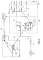
- the safety interface 26 controls a series of four actuators 16 formed, for example, by remote-controlled current cut-off devices D1, D2, D3, D4, inserted into the outlets of a distribution network low tension.
- the structure of the mechanism of such a switching device is described in detail in the French patent application? 82 18551 of 3-11-1982 of the plaintiff, the mechanism authorizing a remote control of closing and / or opening, and a local trip trigger command on fault.
- the electronic supply circuit of the above-mentioned switching device is the subject of French patent application No. 82 20111 of 29-11-1982 of the applicant.
- Each breaking device D1, D2, D3, D4 is associated with a system of auxiliary contacts CAD opening, CAF closing and fault CD, intended to signal the state of the device to the LEC reading register. Some network departures have priority and other departures have non-priority, and the four devices D1, D2, D3, D4 belong to a series of the same priority.
- the output channel V2 of the control unit UC is composed for this purpose of a priority line LP and a non-priority line LNP each intended to send control orders, in particular load shedding and relesting to the same series of devices.
- a priority selector SP makes it possible to choose the type of priority for a predetermined safety interface 26. In the example of FIG.
- the selector SP is switched to the priority line LP of the control unit UC, and the interface 26 controls the four devices D1, D2, D3, D4 of the same series ballasting associated with four priority departures.
- the safety interface card 26 can of course control a different number of switching devices depending on the network structure.
- the output channel V2 of the control unit UC can also include a plurality of lines of varying priority; the number of pads of the priority selector SP then corresponds to the number of lines of channel V2.
- the two state memories ME and control memories MC are addressable memories.
- the bus 28 of the monitoring unit US communicates with the bus interface 32 by means of a data bus BD, and with an address selector SA on the card and with a function selector SF for writing and reading. respectively by BA address and BO order buses.
- the address selector SA cooperates with a watchdog CG whose intervention serves to block in the interface 32 the writing function coming from the microprocessor of the surveillance unit US. This then results in a simultaneous blocking of writing of the state memory ME and of the control memory MC in order to avoid any untimely emission of orders in the direction of the apparatuses D1 to D4.
- Each breaking device D1, D2, D3, D4 is bistable and operates as a remote control switch, that is to say that each excitation pulse applied to its control coil by the logic circuit 30 causes a change of state of the contact. mobile, driven either in the stable closed position or in the stable open position.
- a switching device D1 to D4 is in the inactive state "OUT OF EXPL.”, Its corresponding contact is locked by the interface 26 in the open position, since its state (bit 0) is written in the memory state ME which prohibits any operation by the control unit UC.
- Each breaking device D1 to D4 is normally closed via the monitoring unit US, but can nevertheless be unloaded and relested by the control unit UC by means of the validation confirmed by the state memory ME loaded by bit 1 at the corresponding address.
- the state memory ME stores four bits each corresponding to the state (active or inactive) of the four switching devices D1 to D4.
- the output S1 of the state memory ME is assigned to the state of the device D1 and is connected to a first input of an AND gate 36 of the logic circuit 30.
- the other input of the AND gate 36 is controlled through a door OR 37 which can be controlled by two pulses from the control unit UC and the monitoring unit US. The pulse of the latter is delivered by the output S1 of the control memory MC.
- An adapter circuit 38 is interconnected between the output of the AND gate 36 and the breaking device D1.
- the output S1 of the state memory ME applies to the AND gate 36 a validation order (bit 1) or an inhibition order (bit 0) depending on the state "EN EXPL.” or "OUT OF EXPL.” of the switching device D1.
- the power source of the state memory ME and of the logic circuit 30 is double and results from the power supply common to the monitoring unit US and to the control unit UC.
- a DC / DC converter 40 galvanically isolates the 5 V voltage of the control unit UC from one of the inputs of an OR gate 42, the other input of which is connected to the 5 V voltage of the US surveillance unit.
- the output of the OR gate 42 is used to supply the state memory ME and the logic circuit 30. The supply is thus retained in the event of a failure of one of the UC or US units, and the state of the devices D1 to D4 is saved.
- the microprocessor used in the US monitoring unit is the 68000 from MOTOROLA, and that of the UC control unit is the 68705 from MOTOROLA.
- the closing order is sent by the output S1 of the control memory MC, the latter being selected in writing in a manner similar to that described above for the process of loading the state memory ME.
- Bit 1 is engraved in the control memory MC for a predetermined duration (for example 50 ms) and this results in a calibrated pulse which passes through the OR gate 37 and the AND gate 36 so as to actuate the device D1. The latter changes state and closes.
- the other devices D2, D3, D4 are closed in a similar way to that of D1 using the outputs S2, S3, S4 of the state memories ME and of control MC.
- the procedure is absolutely identical since the D1 device operates as a remote control switch. After emission of the pulse calibrated by the output S1 of the control memory MC, the device D1 opens. The monitoring unit US then loads bit 0 in the state memory ME, which corresponds to the inactive state "OUT OF EXPL. Of the device D1. The output S1 of the state memory ME then applies a inhibit command at the AND gate 36, which prohibits any subsequent control of D1 from the control unit UC, D1 is thus locked in the open position.
- the state of the breaking devices D1 to D4 associated with the safety interface 26 is initially displayed in the state memory ME by the monitoring unit US.
- the opening control signal (load shedding) delivered by the line LP of the control unit UC is applied to the OR gate 37 associated with each breaking device D1, D2, D3, D4.
- the corresponding AND gate 36 of the logic circuit 30 blocks or passes the control signal coming from the control unit UC according to the state of the corresponding output S1 to S4 of the state memory ME.
- the logic circuit 30 will only allow the two control signals to pass in the direction of the devices D1 and D3.
- the four AND gates 36 of logic circuit 30 receive two validation orders of outputs S1 and S3 and two inhibition orders of the two other outputs S2 and S4 of the state memory ME.
- the operation is similar to that described above.
- this state memory ME controlled by the monitoring unit US makes it possible to avoid untimely closings of the devices D1 to D4 during the load shedding and relesting operations.
- the content of the state memory ME can be read by the monitoring unit US during a control procedure. Note that the operation of the cut-off devices D1 to D4 by the control unit UC is dependent on their states displayed in the state memory ME by the monitoring unit US. The operation is authorized when the device is in the "EXPL.” State. If the device is in the "NON EXPL.” State, any operation by the UC control unit is prohibited. In the event of failure of the monitoring unit US, the content of the state memory ME is saved, and the devices D1 to D4 in the state "IN EXPL.” can be operated by the control unit UC.
- each device D1 to D4 can be operated individually by the monitoring unit US.
- circuit breaker 54 and the alternator output of the GE group are respectively connected by conductors 56, 58 to a PN1, PS1 or normal / emergency reverser in connection with a distribution busbar 60, the latter being equipped with a plurality of user feeders protected and controlled by switching devices D1 to Dn of the type described in FIG. 3.
- PN1, PS1 or normal / emergency reverser in connection with a distribution busbar 60, the latter being equipped with a plurality of user feeders protected and controlled by switching devices D1 to Dn of the type described in FIG. 3.
- the permutator PN1, normal / backup PS1 and the cut-off devices D1 to Dn are housed in a low-voltage switchgear TBT controlled by a computer system 10 comprising a control unit UC / TBT and a monitoring unit US / TBT equipped with a safety interface 26 described with reference to FIG. 3.
- the control unit UC includes a first output which directly controls the permutator PN1, PS1, and a second output, similar to the channel V2 in FIG. 3, which controls the operation of the devices D1 to Dn via one or more safety interfaces 26.
- the TBT table also contains the sensors necessary for energy monitoring and metering.
- the standby GE generator is installed in a TGE switchboard which also contains the protections for the alternator, the actuators and sensors for the electrical and electronic equipment, a UC / GE control unit and a US / GE monitoring unit.
- the GE group and its electronic environment on the TGE switchboard are completely autonomous.
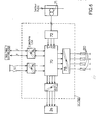
- FIG. 5 shows a variant of FIG. 4, with two identical TBT-A and TBT-B switchboards in parallel supplying two busbars 60 belonging to two outgoing groups A and B.
- the same letters or reference numbers are used to designate identical elements.
- the two processes of fig. 4 are replaced in this application by three methods.
- the architecture of fig. 5 brings up a generator GE which cooperates with two control units UC / GE-A and UC / GE-B to obtain a predetermined availability target.
- the first control unit UC / GE-A in the TGE switchboard is interconnected by link c with the control unit UC / TBT-A.
- the second control unit UC / GE-B of the table TGE is connected by another link c to the control unit UC / TBT-B.
- a bidirectional asynchronous serial link m connects the two monitoring units US / TBT-A and US / TBT-B.
Landscapes
- Physics & Mathematics (AREA)
- General Physics & Mathematics (AREA)
- Engineering & Computer Science (AREA)
- Automation & Control Theory (AREA)
- Safety Devices In Control Systems (AREA)
Applications Claiming Priority (2)
| Application Number | Priority Date | Filing Date | Title |
|---|---|---|---|
| FR8404182 | 1984-03-15 | ||
| FR8404182A FR2561413B1 (fr) | 1984-03-15 | 1984-03-15 | Systeme informatique a structure multiprocesseur pour la commande et le controle d'un procede |
Publications (1)
| Publication Number | Publication Date |
|---|---|
| EP0155213A1 true EP0155213A1 (de) | 1985-09-18 |
Family
ID=9302157
Family Applications (1)
| Application Number | Title | Priority Date | Filing Date |
|---|---|---|---|
| EP85400404A Withdrawn EP0155213A1 (de) | 1984-03-15 | 1985-03-04 | Bearbeitungsanlage mit Mehrprozessorenstruktur zur Steuerung und Kontrolle eines Verfahrens |
Country Status (2)
| Country | Link |
|---|---|
| EP (1) | EP0155213A1 (de) |
| FR (1) | FR2561413B1 (de) |
Cited By (11)
| Publication number | Priority date | Publication date | Assignee | Title |
|---|---|---|---|---|
| FR2610120A1 (fr) * | 1987-01-26 | 1988-07-29 | Merlin Gerin | Ensemble de commande et de protection connectant un reseau de communication local a un processus industriel |
| EP0276937A1 (de) * | 1987-01-29 | 1988-08-03 | British Gas plc | Sicherheitsmonitor |
| FR2651890A1 (fr) * | 1989-09-11 | 1991-03-15 | Siemens Bendix Automotive Elec | Dispositif de detection et de discrimination de defauts de fonctionnement d'un circuit d'alimentation electrique. |
| FR2761173A1 (fr) * | 1997-03-19 | 1998-09-25 | Schneider Automation | Module d'automate programmable |
| WO2000028390A1 (de) * | 1998-11-09 | 2000-05-18 | Siemens Aktiengesellschaft | Verfahren zum überprüfen einer ausgabeeinheit |
| EP0915400A3 (de) * | 1997-11-06 | 2000-09-13 | Siemens Aktiengesellschaft | Periphere Steuereinheit für ein Prozessleitsystem |
| WO2002100041A1 (en) * | 2001-06-06 | 2002-12-12 | Kvaser Consultant Ab | Arrangement and method for system of locally deployed module units, and contact unit for connection of such a module unit |
| WO2005003869A1 (de) * | 2003-07-04 | 2005-01-13 | Pilz Gmbh & Co. Kg | Vorrichtung und verfahren zum automatisierten steuern eines betriebsablaufs bei einer technischen anlage |
| CN104020685A (zh) * | 2013-02-28 | 2014-09-03 | 发那科株式会社 | 具备可装卸的操作盘的控制系统 |
| EP1589386B1 (de) | 2004-04-16 | 2018-01-10 | Sick Ag | Prozesssteuerung |
| CN114157182A (zh) * | 2020-09-08 | 2022-03-08 | 施耐德电器工业公司 | 用于中压断路器和开关的控制界面 |
Families Citing this family (1)
| Publication number | Priority date | Publication date | Assignee | Title |
|---|---|---|---|---|
| FR2895533B1 (fr) * | 2005-12-26 | 2008-05-09 | Brandt Ind Sas | Dispositif de commande electronique d'un appareil domestique |
Citations (2)
| Publication number | Priority date | Publication date | Assignee | Title |
|---|---|---|---|---|
| GB2057207A (en) * | 1979-08-27 | 1981-03-25 | Gen Electric | Relay switching apparatus |
| US4365297A (en) * | 1980-12-29 | 1982-12-21 | Forney Engineering Company | Industrial control system with distributed computer implemented logic |
-
1984
- 1984-03-15 FR FR8404182A patent/FR2561413B1/fr not_active Expired
-
1985
- 1985-03-04 EP EP85400404A patent/EP0155213A1/de not_active Withdrawn
Patent Citations (2)
| Publication number | Priority date | Publication date | Assignee | Title |
|---|---|---|---|---|
| GB2057207A (en) * | 1979-08-27 | 1981-03-25 | Gen Electric | Relay switching apparatus |
| US4365297A (en) * | 1980-12-29 | 1982-12-21 | Forney Engineering Company | Industrial control system with distributed computer implemented logic |
Cited By (19)
| Publication number | Priority date | Publication date | Assignee | Title |
|---|---|---|---|---|
| FR2610120A1 (fr) * | 1987-01-26 | 1988-07-29 | Merlin Gerin | Ensemble de commande et de protection connectant un reseau de communication local a un processus industriel |
| EP0278802A1 (de) * | 1987-01-26 | 1988-08-17 | Merlin Gerin | Steuer- und Schutzeinrichtung, die ein lokales Kommunikationsnetz an einen industriellen Prozess anschliesst |
| EP0276937A1 (de) * | 1987-01-29 | 1988-08-03 | British Gas plc | Sicherheitsmonitor |
| GB2200476B (en) * | 1987-01-29 | 1991-02-06 | British Gas Plc | Monitor system |
| US5063527A (en) * | 1987-01-29 | 1991-11-05 | British Gas Plc | Monitor system |
| FR2651890A1 (fr) * | 1989-09-11 | 1991-03-15 | Siemens Bendix Automotive Elec | Dispositif de detection et de discrimination de defauts de fonctionnement d'un circuit d'alimentation electrique. |
| EP0418665A1 (de) * | 1989-09-11 | 1991-03-27 | Siemens Aktiengesellschaft | GerÀ¤t zum Nachweis und zur Unterscheidung von funktionellen Fehlern in einer elektrischen Versorgungsschaltung |
| US5161112A (en) * | 1989-09-11 | 1992-11-03 | Siemens Aktiengesellschaft | Device for sensing and discriminating operational faults in an electrical power supply |
| FR2761173A1 (fr) * | 1997-03-19 | 1998-09-25 | Schneider Automation | Module d'automate programmable |
| EP0915400A3 (de) * | 1997-11-06 | 2000-09-13 | Siemens Aktiengesellschaft | Periphere Steuereinheit für ein Prozessleitsystem |
| WO2000028390A1 (de) * | 1998-11-09 | 2000-05-18 | Siemens Aktiengesellschaft | Verfahren zum überprüfen einer ausgabeeinheit |
| US6650950B2 (en) | 1998-11-09 | 2003-11-18 | Siemens Aktiengellschaft | Method for monitoring an output unit |
| WO2002100041A1 (en) * | 2001-06-06 | 2002-12-12 | Kvaser Consultant Ab | Arrangement and method for system of locally deployed module units, and contact unit for connection of such a module unit |
| US7882275B2 (en) | 2001-06-06 | 2011-02-01 | Xinshu Management, L.L.C. | Arrangement and method for system of locally deployed module units, and contact unit for connection of such a module unit |
| US8195841B2 (en) | 2001-06-06 | 2012-06-05 | Xinshu Management L.L.C. | Communicating with a first and second protocol |
| WO2005003869A1 (de) * | 2003-07-04 | 2005-01-13 | Pilz Gmbh & Co. Kg | Vorrichtung und verfahren zum automatisierten steuern eines betriebsablaufs bei einer technischen anlage |
| EP1589386B1 (de) | 2004-04-16 | 2018-01-10 | Sick Ag | Prozesssteuerung |
| CN104020685A (zh) * | 2013-02-28 | 2014-09-03 | 发那科株式会社 | 具备可装卸的操作盘的控制系统 |
| CN114157182A (zh) * | 2020-09-08 | 2022-03-08 | 施耐德电器工业公司 | 用于中压断路器和开关的控制界面 |
Also Published As
| Publication number | Publication date |
|---|---|
| FR2561413B1 (fr) | 1989-04-14 |
| FR2561413A1 (fr) | 1985-09-20 |
Similar Documents
| Publication | Publication Date | Title |
|---|---|---|
| FR2503922A1 (fr) | Installation de coupure d'un reacteur nucleaire | |
| EP0155213A1 (de) | Bearbeitungsanlage mit Mehrprozessorenstruktur zur Steuerung und Kontrolle eines Verfahrens | |
| US6892145B2 (en) | Method and system for conditionally triggered system data capture | |
| EP0278802B1 (de) | Steuer- und Schutzeinrichtung, die ein lokales Kommunikationsnetz an einen industriellen Prozess anschliesst | |
| EP0736946B1 (de) | Schnittstellenmodul für einen Feldbus und ein elektrisches Steuer- und Schutzgerät eines Elektromotors | |
| EP3001535B1 (de) | Schutzsteuerungssystem für einen prozessbus, zusammenführungseinheit und berechnungsvorrichtung | |
| FR2508246A1 (fr) | Installation electrique a unite de commande acceptant des erreurs | |
| EP0531230A1 (de) | Verteilungsvorrichtung für elektrische Energie mit Isolationskontrolle | |
| EP3390133A1 (de) | Sicherheitsmodul und ladestation mit sicherheitsmodul | |
| EP1307804A2 (de) | Wartungssystem einer geräteeinheit | |
| CA2080522C (fr) | Dispositif pour la determination de l'etat d'un appareil et en particulier de l'etat ouvert ou ferme d'un appareil electrique a l'aide de contacts auxiliaires | |
| EP0232636B1 (de) | Einrichtung zur Unterstützung der Wartung einer elektromechanischen Installation, die Mittel zur automatischen Überwachung und Steuerung enthält | |
| EP0023689A1 (de) | Logische Vorrichtung zur Vorverarbeitung von Alarmsignalen | |
| WO1989012345A1 (en) | Controller and a network controller system | |
| EP0704952B2 (de) | Selbstüberwachungssystem, insbesondere für elektrische Vorrichtung, vorzugsweise für einen Hochspannungs-SF6-Leistungsschalter | |
| FR2489964A1 (fr) | Equipement de commutation utilisable dans un appareil de test | |
| FR2701129A1 (fr) | Interface de puissance de sécurité. | |
| FR2620828A1 (fr) | Localisateur de pannes sur un systeme de transmission d'energie electrique | |
| EP0337235B1 (de) | Schutzrelais-Prüfanordnung für die Verwendung während des Betriebs des Relais | |
| FR2658010A1 (fr) | Systeme d'eclairage de secours pour installations alimentees par un reseau electrique. | |
| US11749984B2 (en) | Output contact failure monitor for protection relays in electric power systems | |
| EP0197835A1 (de) | Elektrische Lastverteiler-Einrichtung | |
| JPS605918B2 (ja) | 監視装置 | |
| SU1149349A1 (ru) | Устройство дл аварийного ограничени мощности электростанции | |
| FR2643196A1 (fr) | Dispositif de gestion et de surveillance centralisees d'une installation electrique |
Legal Events
| Date | Code | Title | Description |
|---|---|---|---|
| PUAI | Public reference made under article 153(3) epc to a published international application that has entered the european phase |
Free format text: ORIGINAL CODE: 0009012 |
|
| AK | Designated contracting states |
Designated state(s): AT BE CH DE GB IT LI NL SE |
|
| 17P | Request for examination filed |
Effective date: 19851219 |
|
| 17Q | First examination report despatched |
Effective date: 19870518 |
|
| STAA | Information on the status of an ep patent application or granted ep patent |
Free format text: STATUS: THE APPLICATION HAS BEEN WITHDRAWN |
|
| 18W | Application withdrawn |
Withdrawal date: 19870905 |
|
| RIN1 | Information on inventor provided before grant (corrected) |
Inventor name: FRANCON, CLAUDE |